Using the EmonTx v3 with the ESP8266 Huzzah WIFI module

Following on from the forum post here ESP8266 Wifi Developments. This is a brief guide on how to use the Adafruit ESP8266 Huzzah WIFI breakout module with an EmonTx v3 to make a simple WIFI enabled energy monitor that posts to a remote emoncms server such as emoncms.org.

Note: this is an ongoing development project, but is a useful option in its present form

In the future, we may integrate the ESP8266 module directly on the EmonTx PCB. For now, the ESP8266 Huzzah module provides a good way to get this up and running while we continue to develop the firmware and do extended testing. It also provides backwards compatibility for existing EmonTx v3’s.

To setup an EmonTx v3 + ESP8266 Wifi energy monitor you will need:

Setting it up

1. Upload EmonTx v3 EmonESP Compatible Arduino Firmware.

The firmware running on the ESP8266 module expects data to be sent via serial in a specific format, a json like key:value string of the form: P1:100,P2:250,P3:150

The first step is to upload new firmware to support this format which can be found here:

There is a getting started guide for uploading Arduino firmware here:
https://openenergymonitor.org/emon/buildingblocks/setting-up-the-arduino-environment

2. Upload EmonESP firmware to ESP8266 WIFI module

See installation notes here for using the Arduino IDE or Platform IO:

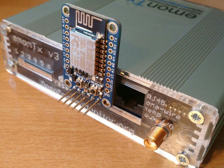
Note: before soldering any headers into the ESP8266 huzzah module, see the example image below for soldering a 6 way stackable header to enable the ESP8266 module to sit cleanly against the EmonTx.

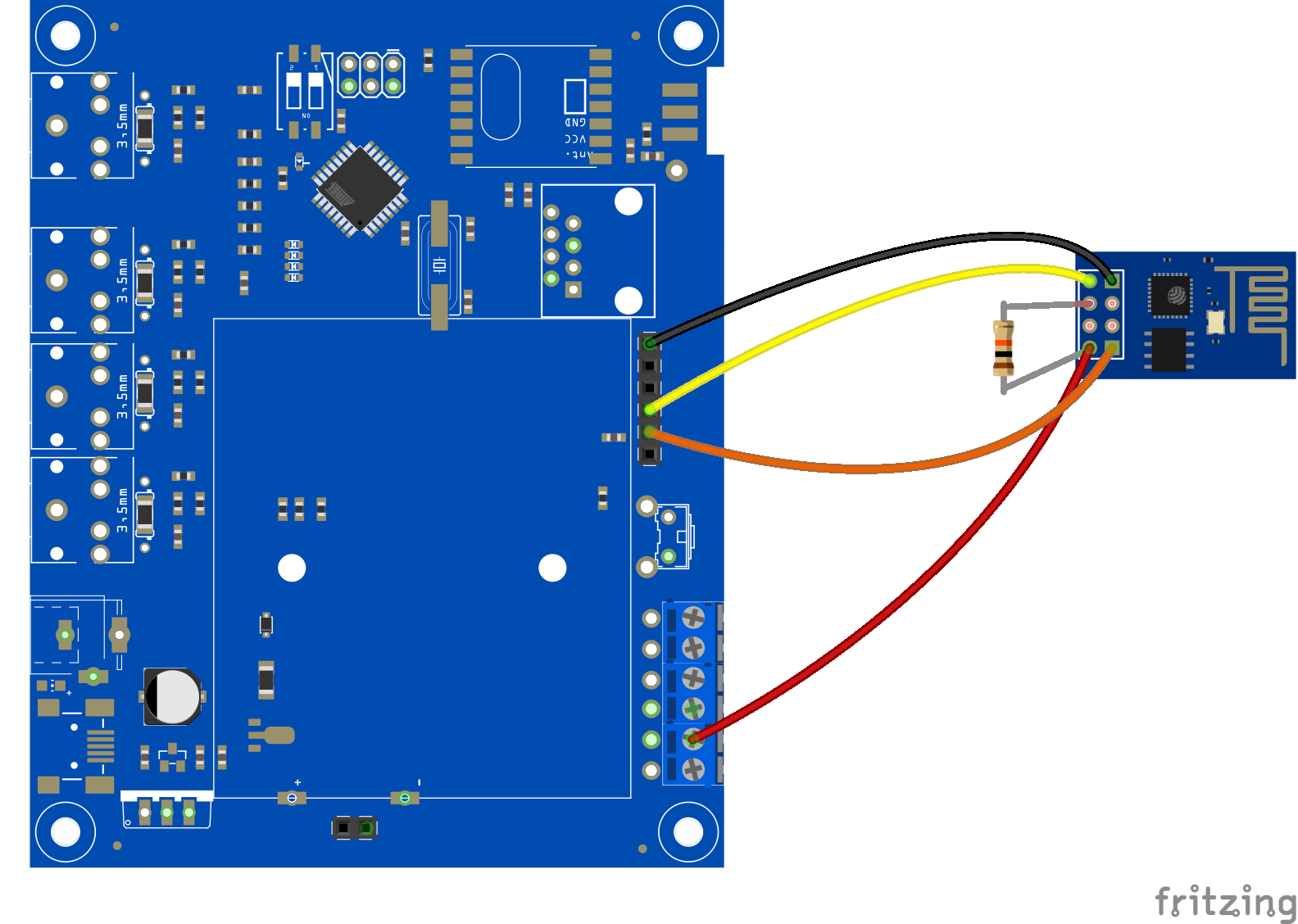
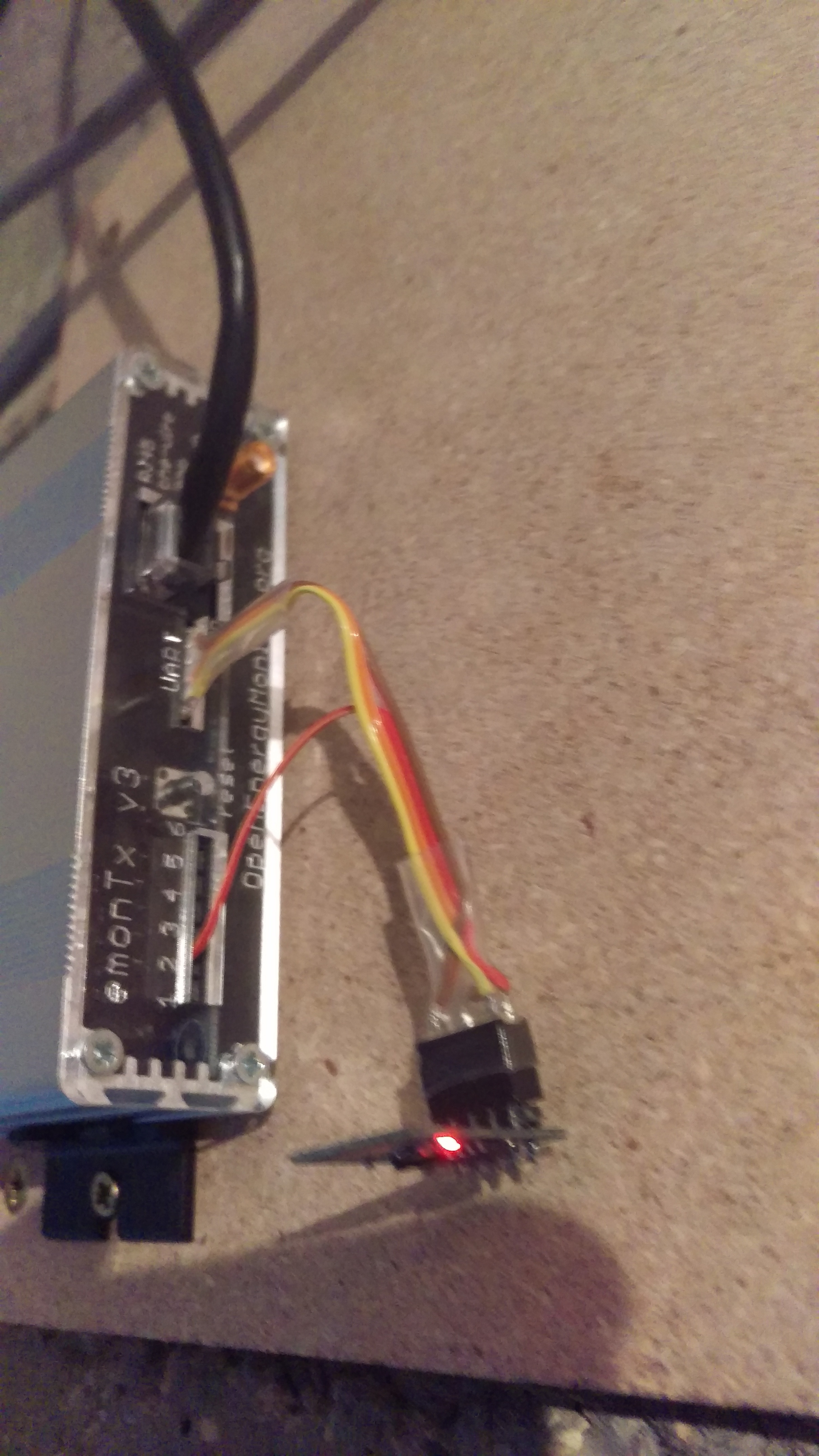
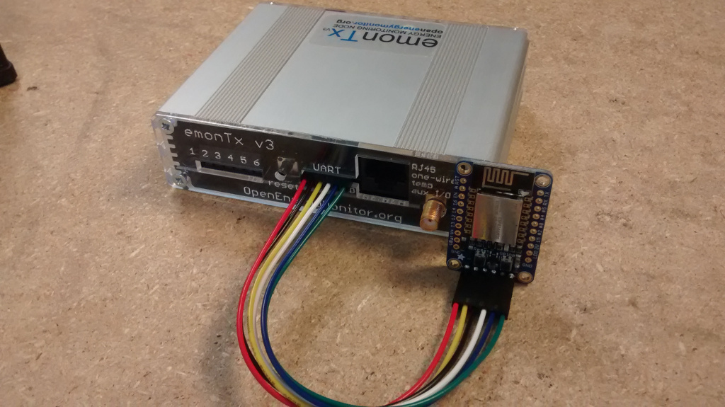
3. Connect EmonTx v3 to ESP module

The ESP8266 can be connected to the EmonTx v3 with a 6 way stackable header as below but a modification needs to be made so the TX line from the EmonTx goes to the RX line of the ESP8266 module as shown in the picture below.

Alternatively, 6 way ribbon cable with the RX/TX line swapped could be used, and may be a bit easier to put together.

N.B. You should connect ONLY the RX pins, and leave the Tx pins not connected, as the pictures below show.

4. Power up and configure

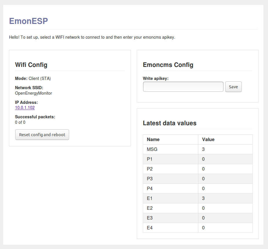
Once powered up, the wifi module starts by broadcasting a hotspot that you connect to directly. You can then scan for wifi networks, select a network, or get the ip address of the monitor on the network (which eliminates the need to use fing or access your router device list). Enter your emoncms.org apikey to connect to an emoncms.org account and see the latest values from the EmonTx in the web interface to verify proper operation.

That’s it. If you follow this and get it working, let us know how you get on!

4 Likes

This is super cool! Can’t wait to try it.

1 Like

Emonesp is working very well in my configuration with Arduino Due / UTFT(480x320p) display, posting data to Emoncms.org every 10 sec with very accurate measurements.
I think this is the future in next developments.
Thank you

2 Likes

Great to hear! Between Glyn and I we now have a number of test systems up and running all performing well at the moment. Stable WIFI connection etc. In terms of ease of use and reducing setup complexity I think its a big step forward - for applications where local storage is not needed/used

Hi, just a quick note/warning to everyone to remember that the ESP8266 is 3.3V and the EmonTX is 5V.

Update: this is incorrect, see below

This is ok with the Huzzah as that has the conversation login on the UART connectors but not for most other ESP8266 boards like the ESP01 I spent most of last night getting EmonESP to run on (was not actually that difficult but had hardware problems rather than software) only to remember that minor fact this morning…

Jeremy

That is not strictly true. The emonTx V3.2 and V3.4 both have an on-board regulator and the processor runs off 3.3 V, as this is required for the RFM12B and RFM69CW radio modules. The emonTx Shield uses both 3.3 V (for the radio) and 5 V (for the analogue input conditioning circuits).

1 Like

So is it just 5V on the UART connector? Are the data lines 3.3v?

You can see exactly what voltages are used where if you look at the circuit diagram. It’s available on the emonTx V3 Wiki via Resources.

Agree with the 3.3 vice 5 Volt issue, but what the devil is the conversation login on the UART?

Sorry auto correct should be ‘conversion logic’

It would be fantastic if you could link several emonTx’s together and use one WiFi module, I also agree that the WiFi is the way forward and gives people more options when putting systems together.

2 Likes

Thanks, then to answer my own questions then the Tx/Rx/Reset lines (on the UART connector) are all 3.3V, just the Vcc that is 5V. So I could pick up a 3.3v from the terminal block and all should be golden. I am a little worried that the regulator may only just be powerful (250mA) to run the ESP and the EmonTX but I will give it a go.

The main reason I started down the road of trying to use the ESP-01 was that you can pick them up for around £2 so if you wanted to run multiple EmonTX you could just have one per EmonTX.

Yup, emonTx V3 UART lines are 3.3V. The ADAFRUIT HUZZAH can be powered from 3-6V (it’s got a built in regulator), therefore the Huzza can be powered directly from the emonTx V3 UART. You will need to power the emonTx via the 5V mini USB socket. The AC-DC power supply circuit on the emonTx V3 will not be able to supply enough current for the ESP.

Good luck, let us know how you get on.

Hi Jeremy,
for esp 01 module( blue or black) flash size is too low to be able to load emonesp firmware and html data. You have to use ESP-12E with 4M flash size for this application, the same chip used in Huzzah module.
Best regards

1 Like

I’m currently thinking about adding an ESP8266 to the EmonTX 3.4 I’ve recently installed instead of the RFM radio. It’s rock solid, but I have a WiFi AP nearby the electricity compartment so it’s just a little more convenient than the RF+base station hardware combo. Though then I’ll need a DC adapter.

But why I posted is that I compiled the EmonESP firmware in PlatformIO and it compiles to about 375kB (spiffs included), so it should fit in the smallest of the ESP boards even with 512kB, in theory. Which is good since the 01 modules are available for a few beans. It’s worth a try, at least.

Hi,
I used arduino ide to load emonesp firmware and data in several ESP-07 and I couldn’t make them work properly. When I loaded firmware and data to ESP-12E everything works as expected. Somewhere in the installation instruction guide is mentioned that should be used ESP-12E and I can confirm and advise that from my own experience.
Best regards

Cracked it last night, now I have the power sorted it the ESP-01 can read the values from the EmonTX. Need to get it setup in place and do some more tests.

As mentioned the current incarnation of the EspEmon firmware is ok to fit in 512MB flash. I am not totally convinced OTA will work but that is one of the things to test.

Will post some pics, wiring and a PR later today.

Jeremy

I don’t think you’ll get OTA working on the 01.

For as much as a beer you could be buying these instead - http://www.banggood.com/D1-Mini-NodeMcu-Lua-WIFI-ESP8266-Development-Board-p-1044858.html?utm_source=google&utm_medium=cpc&utm_campaign=Celc-ad-rm-DM-D1MINI&utm_content=gary&utm_design=27&gclid=CJHvjJ_0-M0CFUa6GwodkMIGag

£4 postage paid. You can’t go wrong. The 01 is false economy.

Simon

For information here is how you wire up the ESP-01;

and a pic of my setup;

I have also raised PR #8 with the changes I needed to make, just really adding the ESP-01 as a board for the project.

I am seeing an issue where it works for a while but then starts reporting key ‘1’ with a value of ‘0’ repeatedly very quickly. Not too sure if that is the EmonESP or EmonTX. I do have a Huzzah board so will give that a go and see if I get the same issue.