Enter Samsung TS. The guy wanted to revert the system to ‘standard’ settings on a WL of 15 30 with no uplift and pump PWM back to 100% #2093 4, he was not happy with my workaround and the comp oscillating, also not happy about the lower flow rates and wanted to ‘see it for himself’. Acccepted that my workaround manually modulating the pump had stabilised the system and put the workload onto the comp to regulate the LWT.
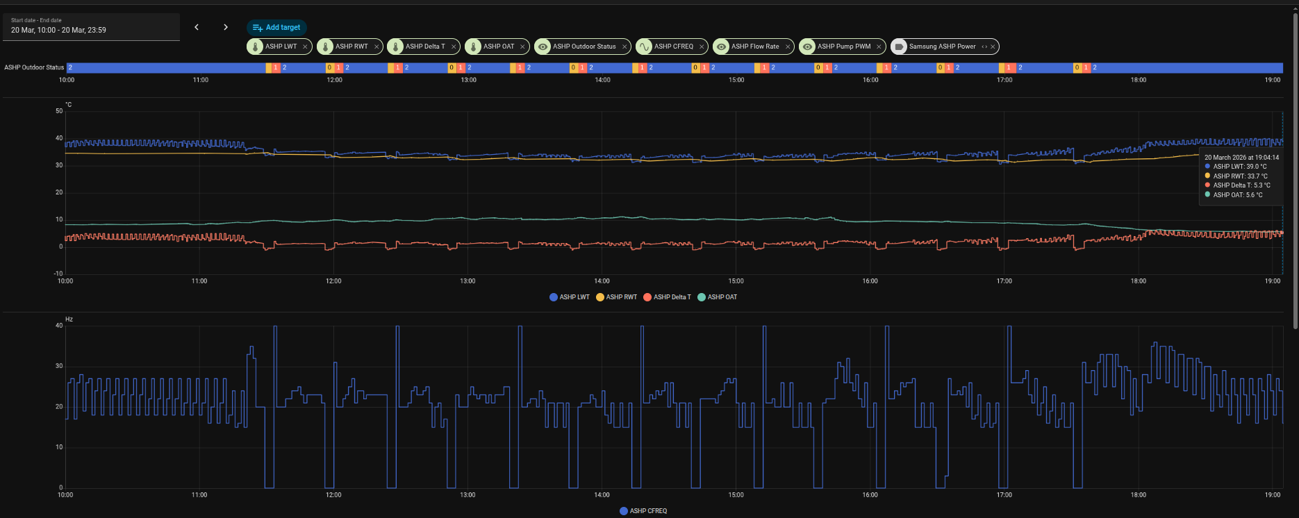
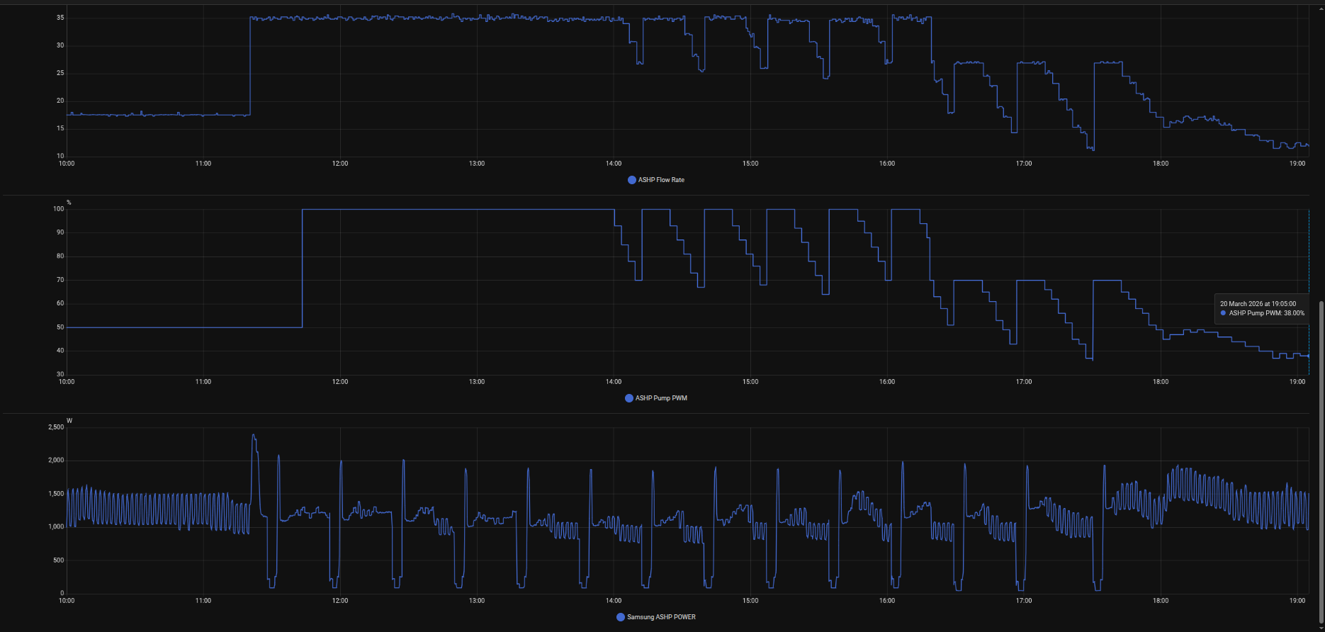
With the expected consequences. We left it running most of the day until I changed the pump limit to 70% because with the pump running pretty much at 100% it was noisy, can’t hear it at max 70% and then at 18:00 I added a couple of degrees uplift using the controller to get some heat in the house and hopefully stabilise it, time will tell. The Samsung guy was as baffled as I am about why the pump was not modulating 7mins 3 mins at thermo off as #2093 4 should do. It just stays on at full whack most of the time. By leaving the pump running at full whack, we get those cyclic fridge sessions where the DT is negative and the unit is taking heat out of the house. You can actually feel it happening, very weird. From 11:20 ish right through the afternoon, the pump never switches off. It does eventually ratchet down to 70% and then very quickly back up to 100%. He thinks there could be an issue with the PWM controller but nothing conclusive. Need to open it up and check all physical wiring etc. He has gone off to check firmware etc.
Pump should modulate on a 7 3 cycle at Thermo Off, which clearly never happens. So it’s ignoring #2093. I did a previous test of #2093 2, and it also did not stop the pump at thermo off. So maybe there is an issue somewhere. Hopefully with a 2 degree extra demand it should help to bring the system back up and stabilise it. Time will tell.
Anyway, I will continue, I am still trying to find the registers I can map for the Target LWT etc.
Also, I now have a NASA cable wired into the unit and will have another Waveshare device tomorrow so I can fire up the NASA side of things. I had previously seen a guide online somewhere that listed all the NASA registers that are accessible, but I can’t seem to find it now. If you know where I can get that, I would be grateful. Not this link pysamsungnasa/docs/index.md at main · pantherale0/pysamsungnasa · GitHub
Or this one:
Or this one:
It was a document that had tables with all of the registers and explanations.
Anyway, the journey continues, thank you for the kind words of encouragement.
It does sound like there may be a fault on your MIM. If Samsung agree, and offer you a replacement PCB, make sure that its a rev 01. This has several additional (and useful) FSVs (inc. user-settable hysterisis on LWT and roomstat), but there are still lots of rev 00s in stock and they may palm you off with one of those if you aren’t careful. (But if you do get the new PCB, read Samsung FSV#6031 Cautionary Note first.)
As for the NASA message listing, I happened to download a copy a few days before it disappeared from Wiki. Here it is, converted to Word: NASA Protocol.docx (77.1 KB).
I also set up a subset of the more relevant (to the HTQ series) messages in Excel, which included a spreadsheet to help with message interpretation. See Samsung ASHP NASA Messages - Updated Table for the background, but I think I may have updated the spreadsheet since and the latest version is here: NASA_Interpreter.xlsx (74.1 KB)
You appear to be extremely knowledgeable about these systems are you a heating engineer? In respect of status messages 0x8001, the doc shows normal as 3, safety as 2, and standby as 1 on my Gen 7; these report as 2 1 0. Normal Ops is 2 safety 1 and standby 0.
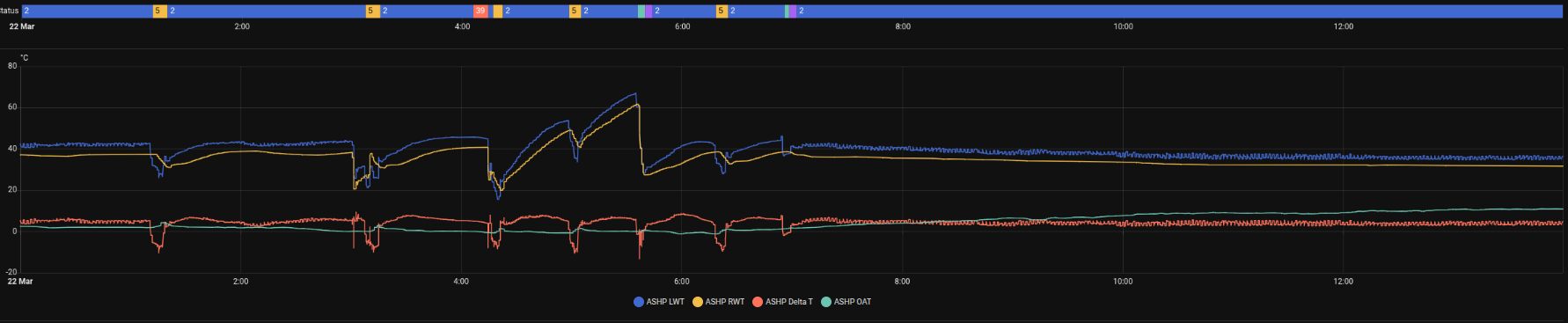
This morning I had a status 39. Everything continued to operate no impact on Comp, Pump PWM or the electrical input unit, which appeared to function normally. It then went to 5 Defrost a few minutes later and then 2 normal ~5 minutes after that. 5 defrost cycles during the night max of ~8 mins and min of ~5 mins. I assume this is totally normal. It was ~0 degrees. Maybe totally coincidentally, the status 39 appeared when the temp dipped below 0 to a min of -0.7 then back up over a ~10 minute period.
There is no status 39 in the doc. Do you have any idea what it is?
Bless you no, @antonical, a humble ex-Chemical Engineer, so pretty clueless on electronics and control, and I would always defer to giants like @Topaz and @toadhall for this kind of thing.
Having said that, here’s what NASA.ptc has to say about 0x8001 (in case you haven’t downloaded SNET-Pro2 yet):
So on the one hand I can see exactly where your 0,1,2,5 values are coming from (e.g. 5 = Deice, aka defrost), and it is well-known that a Samsung defrost cycle (at least on pre-Gen 7 units) lasts ~5-8 minutes (see Samsung ASHPs: Anatomy of a Defrost for the gory details). And on a cold night like last, 5 defrosts is quite believable (and not abnormal).
But 0x8001 = 39 is a new one on me. You can see that the NASA.ptc list goes up to 36, even though values up to 254 are allowed if I interpret the last line correctly. How are you reading this value (given that you don’t use SNET-Pro2)? Via your MIM-B19N and Modbus? In which case I’d be out of my depth, sorry…
Yes via Modbus I mapped 8001 into the additional modbus address space registers 80+ along with things like Flow rate, Pump PWM Outside Air temp.
If anyone knows how I could map the WL Target Flow temp. The temp the Samsung is trying to get to based on the underlying WL settings. I cannot find this. It is one of the last pieces of the puzzle for me to write a more sophisticated automation to curb the antics.
Right now its pretty clunky but doing an amazing job. It looks at the moving averages for LWT RWT looking at the trend up or down etc. It then modulates the PWM up or down. Once the system is stabilised, DT ~5 it hands control back to Samsung. (All rads are balanced to DT 5).
I also have a couple of other automations that sets PWM to Maximum allowed during DHW cycle. Then after the short cycle switch to heating it caps the PWM at 40 for 30 mins. Stabilises the system and then hands control back to Samsung.
The other one looks for the cycle switch from 0 to 1 to 2, 3 mins later it modulates the pump to 40 for an hour then hands control back to Samsung. No more boom and bust cycles!
More importantly, the house is lovely and everyone is very, very happy. Samsung control not so much!
I just need to figure out why the DHW schedule did not happen. It was set for 3-4am but the system did not action it. I was up anyway and manually triggered it to ensure there was DHW for the house.
Samsung through the night, the DHW cycle and after. My automation following the last cycle off from around 7am.
For a Gen6 it is Modbus register 68, NASA register 0x4247, but for a Gen7 ………
It behaves differently depending on whether you have Water Law enabled or not
Water Law enabled. It reflects the flow set point as calculated by the Water Law. It can be changed but will be overwritten some time later by the Water Law calculation.
Water Law disabled. It is now the set point for the water flow and can be set by an external control system (this is the way I use it).
Yeah that register just returns 65535 constantly. It is in the book, but not there on a late 2025 manuafacture Gen 7 Integrated.
All I need to do is read it to get what the device has determined based on WL what the target is at that OAT and PIT. Once I can read it, I can log it, do moving averages etc. Otherwise, I will have to build a lookup table to determine what it “should” be, but I really wanted to see what Samsung thinks it should be. I have OAT, Flow, PWM, RWT, Comp Freq. So the rest is just maths.
Forgive me if I’m teaching you to suck eggs, @antonical, but if all you want is the WL target temp, why don’t you simply calculate it from #2011/2 and #2022/2 like the MIM does? You know
Target WL = m * OAT + c
where m = (#2021 - #2022) / (#2011 - #2012)
and c = #2021 - (m * #2011)
(Suitably bounded, of course, so that if OAT < #2011 or > #2012 it uses the values at these OATs.)
Or maybe I am missing something?
This is what I have in my Virtual sensor list: in case it helps anyone else just add this to your template sensor section:
```
sensor:
name: “ASHP Calculated Target WL”
unique_id: ashp_WL_target
unit_of_measurement: “°C”
state_class: measurement
device_class: temperature
state: >
{# Constants from the -7/50 to 15/32 curve #}
{% set m = -0.818 %}
{% set c = 44.27 %}
  ```
    {# Use actual Outdoor Ambient Temperature sensor #}
    {% set oat = states('sensor.ashp_OAT') | float(0) %}

    {# Calculate Target: m * OAT + c #}
    {% set target = (m * oat) + c %}

    {# Cap the output from the WL FSV range (32 to 50) #}
    {% if target > 50 %}
      {{ 50 | round(1) }}
    {% elif target < 32 %}
      {{ 32 | round(1) }}
    {% else %}
      {{ target | round(1) }}
    {% endif %}
  icon: mdi:target-thermometer
```
OK but just remember that those values of m and c are specific to your particular entries for #2011/1 and #2021/2. If you change them, you’ll have to change your code accordingly.
(PS Rather than entering m and c into your code as constants, why not adjust the code to recalulate them continuously from the FSVs? Then anybody could use your code directly. I can’t imagine that this would slow down the parsing calculations significantly…)
I can’t seem to find a way to map those data registers via Modbus. Maybe they are not available.
RANT
Some of this is totally stupid. Why advertise a Modbus interface which BTW has been around since I left school which, believe me was a very long time ago after Schneider invented it for their PLC’s and has been the standard in industrial control. Then cripple it by not providing key data or even all data that the machine has to give. Totally infuriating.
RANT OVER
Once you get your Waveshare or equivalent, and can get serial data from F1/F2 into your router (thence into your laptop or RPi or whatever), you should be able to programme HA (via @pantherale0’s HA Integration) to do your bidding automatically, without the need for the MIM-B19N and any Modbus coding .
Or, if you don’t actually need automation (only monitoring) you can download SNET-Pro2 (if you want to be able change settings like FSVs manually from the comfort of your laptop) and/or @PeterX’s NASAmonitor (if you just want to watch what’s going on).
Just remember, NASA is not modbus, afaik Samsung only provide a modbus interface via their “special” £130~ converter board (that does nothing more than hold a cache of NASA messages to speak a native modbus protocol).
Yeah it’s not exactly easy to follow. Various NAS messages seem to map ok but I can’t map the WL high/low or get the indoor temp despite trying all of the documented register addresses in the Modbus and NASA docs. Various ‘documented’ mappings of NASA registers onto the FSV’s settable from the indoor controller don’t work on a Ggen7 integrated other do like #2093 for instance.
Yes waiting on another Waveshare Module to interface the unit via NASA to the network. Then I can start to look at your code and see how I can integrate that with HA. Thanks for all the hard work on producing it.
I am assuming it is expecting a normal serial connection 9600, N, 8, 1, EVEN. I would normally config these as servers on the network using RTU over TCP. Is that how you are talking to it?