Caution: This long post considers what is going on in the Outdoor Unit during a defrost cycle. Read on only if you have plenty of time to spare… ![]()
By chance I caught a defrost cycle “on camera” recently, using Samsung SNET-Pro2 software. This displays the real time ASHP controller inputs and output values (Outdoor and Indoor Units), and optionally records them on an Excel spreadsheet at a user-specified sampling interval.
Below is a summary of the results, and a commentary on what I believe is going on in the Outdoor Unit, in the hope that this may be of interest to other Samsung owners (some of whom may not have ready access to Outdoor Unit operating data), and to invite other opinions where I have things wrong.
Background
I switched on the SNET recorder at 09:41 on Jan 10th because I noticed that the evaporator temperature was much lower than expected for the ambient temperature (about -3degC) – the expected compressor suction temperature was about -1degC, but the observed was about ‑14degC. A couple of minutes later a defrost cycle was triggered, and I left the recorder going (with a 10 second data sampling rate) until well after the defrosting had been completed (circuit back to normal).
Here are the raw spreadsheet data, followed by with my personal interpretation of what is going on in the Outdoor Unit during this period:
Defrost Run 1.xls (140.5 KB)
I have annotated each spreadsheet column with a cross-reference (in red) to the data location on the Outdoor Unit PFD (the numbered balloons below):
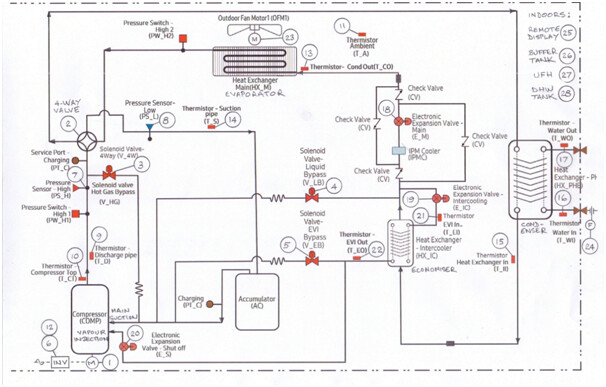
My Interpretation (readers may wish to follow these notes using a printout of the spreadsheet):
Pre-Defrost
At recording start (09:41:12), the circuit was in Normal Operation mode, but the evaporator was already icing up. This can be inferred from the large DT between the ambient temperature (PFD Ref 11 = -2.5degC approx) and the compressor suction temperature (Ref 14 = -14.5degC approx).
Normally this DT is ~2degC, thanks to the controller algorithm for energy minimisation by which suction pressure is maximised consistent with complete refrigerant vaporisation. This is achieved by setting a target compressor suction temperature a couple of degrees above the refrigerant dew point at the suction pressure. (Dew point temperatures for different pressures are pre-programmed into the controller.) This margin allows for a finite temperature approach in the evaporator, and ensures 1-2degC superheat at the compressor suction, guaranteeing that no liquid refrigerant enters the compressor. This target figure appears in spreadsheet as Saturated T_Ps (Ref CC). If the measured compressor suction temperature is higher than target, suction pressure will be increased a little, if lower than target, decreased a little. Compressor suction pressure is controlled by a combination of compressor speed control and Main EEV position (to reduce suction pressure, speed is increased and/or the Main EEV closed, and the reverse for increased suction pressure).
With progressive icing in the evaporator, heat transfer decreases, so the compressor suction temperature will fall towards the EEV outlet temperature (Ref 13), causing the suction pressure to decrease (per the above algorithm). Following recording start (09:41) it can be seen that already the Main EEV (Ref 19) has almost closed (168 versus 2000 wide open), and that the compressor speed is increasing (38 to 41Hz inverter output by 09:44).
The compressor discharge pressure (Ref 7 = 28.7bar) is typical for condensing against RWT (Ref 16 = 45degC). The controller algorithm for energy minimisation ensures that discharge pressure is minimised consistent with complete refrigerant condensation. This is achieved by setting a target condenser outlet temperature (Ref 15) a few degrees below the refrigerant bubble point at the discharge pressure (which is pre-programmed into the controller to allow for a finite temperature approach in the condenser). This ensures no more than a few degC refrigerant subcool at the condenser exit, which minimises equipment sizing. This target figure appears in spreadsheet as Saturated T_Pd (Ref BB = 49degC). If the measured condenser exit temperature is higher than this target, discharge pressure will be decreased a little, if lower than target, increased a little. Compressor discharge pressure is controlled by a combination of compressor speed control and Main EEV position (to increase discharge pressure, speed is increased and/or the Main EEV is closed (and the reverse for decreased discharge pressure).
It can also be seen that during the pre-defrost period, some refrigerant is being diverted via the economiser exchanger side-stream to the compressor vapour injection (VI) port, probably in response to the Main EEV closure. The takeoff EEV (Ref 19) is half open (154 versus 300 wide open) and the injection EEV (Ref 20) is wide open (2000). That there is little temperature change between the side-stream inlet (Ref 21 = 12.5degC) and outlet (Ref 22 = 12.9degC) is consistent with the small flow going forward to the Main EEV (which is nearly closed), the economiser (aka intercooler) heat exchanger duty being very small.
Pre-defrost, the evaporator fan (Ref 23) has been going at full speed (550rpm).
The circulating fluid (in my case 20vol% propylene glycol) LWT (Ref 17 = 48.3degC) is approaching the target WL temperature of 50degC, and the RWT (Ref 16 = 45.1degC) along with the circulation rate (Ref 24 = 28lpm) reflects the heat being delivered by the ASHP. At the time of this run, the roomstat would still have been showing a demand (I have a large night-time setback, and by 09:41 the roomstat was still not satisfied).
09:45:01 Defrost Start
Almost certainly, this would have been because condition B of the Samsung defrost algorithm Start Condition had been met (Ref 13 below the L1 line below for 3minutes):
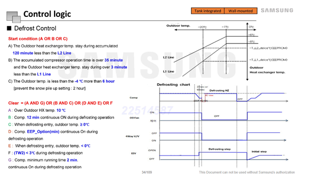
The overall Samsung defrost strategy appears to be to minimise compressor energy consumption during the defrost cycle by minimising its pressure ratio – it is only necessary to maintain a discharge temperature well above that needed to rapidly thaw the evaporator ice build-up (25-30degC) (but not so high as to risk thermal shock to the evaporator).
09:45:01 – 09:45:21 Immediate Consequences
Once the defrost cycle is triggered, several things happen:
- The 4-way valve (Ref 2) flips to reverse the refrigerant flow, and (hot) compressor discharge (Ref 9, about 60degC) is routed to the evaporator to melt the ice build-up.
- The compressor inverter speed is reduced to minimum (Ref 6 = 20Hz). This, along with the Main EEV (Ref 18) opening fully, and closure of the economiser side-stream flow (Ref 19) reduces the compressor discharge pressure considerably, with the consequent reduction in compressor energy requirement, as indicated by Compressor Current1 (Ref 12) which falls from ~6A to ~0.5A immediately.
- The vapour injection bypass valve (Ref 5) also opens, though since the source valve (Ref 19) and vapour injection valve (Ref 20) are closed, no bypass flow actually takes place.
- Within a few seconds (09:45:11) the compressor pressure ratio has reached its minimum (discharge 608kPa, suction 461kPa) and the compressor speed is ramping up again. The refrigerant entering the condenser (Ref 15 = 40degC) is now colder than the circulating fluid – approx values RWT (Ref 16) = LWT (Ref 17) = 45degC – so heat is now being removed from the house. Compressor discharge (Ref 9) is still 60degC so the evaporator ice will be thawing rapidly.
09:45:41 Defrost Conditions Established
By this time the compressor inverter frequency has ramped back up to synchronous (Ref 6 = 50Hz) and this is then maintained until the initial “defrost clear” signal occurs.
09:48:21 Defrost Clear Conditions Satisfied
Referring to the above Defrost Control Logic diagram, the Clear condition is (A+G) on this occasion – this occurs when the evaporator outlet temperature (Ref 13) exceeds 10degC. This results in the compressor speed being again reduced to minimum (Ref 6 = 20Hz inverter frequency), the Main EEV (Ref 18) moving from fully open to 20% open, and the hot gas recycle valve (Ref 3) opening, presumably in preparation for the operation of the 4-way valve, which occurs a few seconds later. Once the 4-way valve and Main EEV are in their normal (heating) position, the refrigerant temperature at the evaporator (Ref 13) soon starts to fall again.
Around this time, the compressor discharge temperature has reached its minimum (Ref 9 = 27degC) though its pressure ratio is still low – discharge (Ref 7) about 2000kPa, suction (Ref 8) about 1600kPa. Also around this time the LWT (Ref 17) has reached its minimum temperature (approx 28degC), though RWT continues to fall due to the thermal inertia of the emitter system.
09:48:21 – 09:48:51 Prepare for Defrost Completion
Over the next 30s the compressor speed is ramped back up to synchronous (50Hz ex inverter) where it stays until the “defrost complete” signal occurs, the evaporator fan starts and ramps up to full speed. The effect of the Main EEV (Ref 18) having been put back on control results in a rapid reduction in compressor suction pressure (Ref 8), and since the discharge pressure is continuing to rise, a consequent increase in compressor power consumption (inferred from Compressor Current1, Ref 12).
09:49:21 – 09:49:31 Defrost Complete
It appears that just prior to “Defrost complete” (Ref AA), the controller switches compressor speed control to the “normal operation” algorithm, resulting in a small speed reduction. Normal operation is reinstated by 09:49:31, exactly 60s after “defrost clear”. This may be the result of a controller timer, though it is not mentioned in the above Control Logic diagram, so remains speculation. At the same time, the compressor vapour injection route (Ref 20) is reopened, followed by reinstatement of economiser flow (Ref 19), and further closure of the Main EEV (Ref 18). At this point, the vapour injection bypass valve (Ref 5) is still open, so the economiser side-stream flow is routed partly to vapour injection (Ref 20) and partly to its bypass (Ref 5). The economiser operation algorithm has not been issued by Samsung (start and stop criteria), but its use has been observed more frequently at low ambient temperatures.
09:49:31 – End of Recording (09:58:31)
Compressor speed continues to increase in an attempt to get LWT up to its Water Law target of 50degC, at one stage (09:55:31) reaching 54Hz inverter frequency. This target has not been reached by the end of the recording.
Although the evaporator inlet temperature (Ref 13) dropped as low as -13degC (09:52:31), no further defrost was triggered. We do not know the slope of the L1 line on the above defrost control logic diagram, though Samsung have given this example:
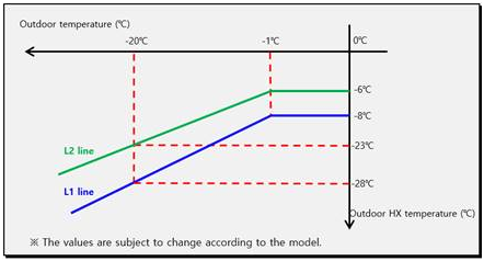
If this is applicable to my installation, at an ambient temperature of -2degC, the required evaporator inlet temperature for defrost initiation would be -9degC. This was exceeded between 09:51.11 and 09:54:31 (3m20s, so longer than the 3min required for triggering). I surmise that the controller prevents another defrost within a certain time of the previous one (tbc).
The only other event recorded is the closure of the vapour injection bypass valve (Ref 5) at 09:57:01, resulting in the whole economiser side-stream flow being routed to vapour injection (Ref 20).
Energy Flows
The spreadsheet has been extended to calculate the circulating fluid (glycol in my case) density (kg/m3), specific heat (J/kg/K), mass flow (kg/s), and thus heat transferred to or from it (W) at each interval.
During defrost, the negative heat flows (i.e. energy taken from the house) can be converted to Wh per 10s increment. Summing these over the complete defrost gave a total of 570Wh.
Interestingly, in the period following defrost, the heat duty peaked at over 10600W (compared with the heat pump nameplate duty of 8000W).
If you have made it this far, please post any comments on the foregoing, particularly if you spot any mistakes (I’m still a learner…)