This post summarises some of the available options for monitoring operating data directly from your heat pump controller, including the refrigerant side of the Outdoor Unit (most current OEM monitoring packages omit this).
Controller monitoring is especially useful to those interested in understanding some of the control algorithms that Samsung apply, in order to explain observed heat pump performance, and to help with settings optimisation.
As you will see below, there are a couple of low-cost options for monitor installation – around £17 if you can run a cable between the controller and your PC, or as little as £24 if you cannot (Jan 2025 prices) – either way, this is a modest investment if it helps you unravel the mysteries of your Outdoor Unit and thus reduce your running costs.
Background
Samsung incorporate the same basic Control Kit (MIM-E03*N) in all their current ASHP ranges (ODU, Gen 6, EHS/HTQ, and Gen 7). The controller may be located in a standalone cabinet, or integral with a Samsung Indoor Unit, or within the Outdoor Unit (Gen 7 Integrated only).
The controller circuit board contains a 6-terminal block (labelled F1-F2-V1-V2-F3-F4), which is used for serial communication (RS485) with other equipment:
- F1-F2 are used for data transfer to/from the Outdoor Unit (though not the Gen 7 Integrated – this is wired directly)
- V1 is a 12V DC supply
- V2 is digital ground
- F3-F4 are used for data transfer to/from the Remote Controller (MWR-WW10N)
The serial data available at the F* terminals include controller input/output digital/status values (discussed further below) which, with suitable interpretation software, can be used for monitoring purposes. These data include those from the Outdoor Unit (e.g. refrigerant pressures and temperatures, compressor inverter frequency, and EEV and SOV positions) and some indoor values (e.g. circulating fluid flow and DHW tank and room temperatures).
There are several ways to set up remote (computer) monitoring of the controller data, the main ones being:
- Via a Samsung MIM-C02N interface (or a 3rd party RS485 to USB equivalent)
- Via a 3rd party RS485 to Ethernet adapter
- Via a Samsung MIM-B19N ModBus interface
This post deals with the first two – the intention is to add information on the MIM-B19N at a later date.
MIM-C02N Interface
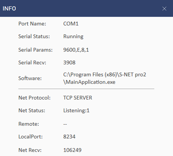
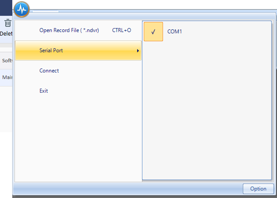
This is the simplest option as it only requires a 2-core cable between F1-F2 and the interface – which plugs into a USB port on your computer – and downloading Samsung SNET-Pro2 software.
However this official Samsung interface is not cheap (Jan 2025 cost from Midsummer Wholesale £199). The SNET software is free to download from https://s3.amazonaws.com/samsung-files/Tech_Files/SNET+Pro+and+SNET+Pro+2+Service+Software/Snet+Pro+Service+Software_SNET+Pro+2+Instructions.pdf. This link – correct as of Jan 2025 – includes step-by-step instructions on connecting the interface and installing the SNET software.
Although the (RS-485) cable length is effectively unlimited, the RS485 interface must be physically connected to your computer. This may involve running the RS485 cable through one or more walls, or temporarily relocating your computer close to the controller when a monitoring run is required.
Note that in addition to data monitoring, the MIM-C02N does provide some additional functionality, such as the downloading of Samsung firmware updates, which is not available with other monitoring options.
A low-cost alternative is to install a 3rd party RS485 to USB interface, such as https://www.waveshare.com/wiki/USB_TO_RS485. This is available from Amazon for about £17 (Jan 2025 price). The installation is the same as for the MIM-C02N, so the above SNET instructions can be used. Importantly, however, the 3rd party interface does not offer the firmware downloading functionality of the Samsung interface
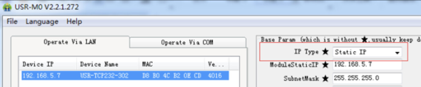
RS485 to Ethernet Adapter
Briefly, this approach involves:
- Connecting the ASHP controller to your broadband router via the adapter and Ethernet cable(s)
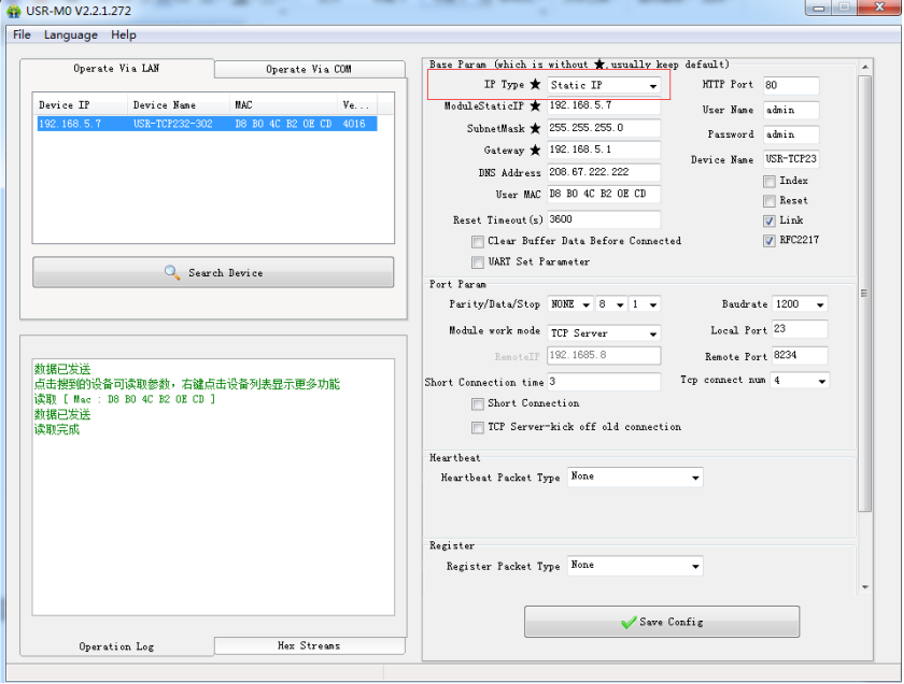
- Assigning a permanent IP address to the adapter
- Configuring the adapter for communication with the ASHP controller
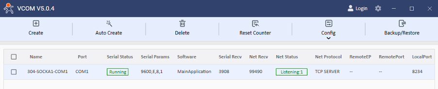
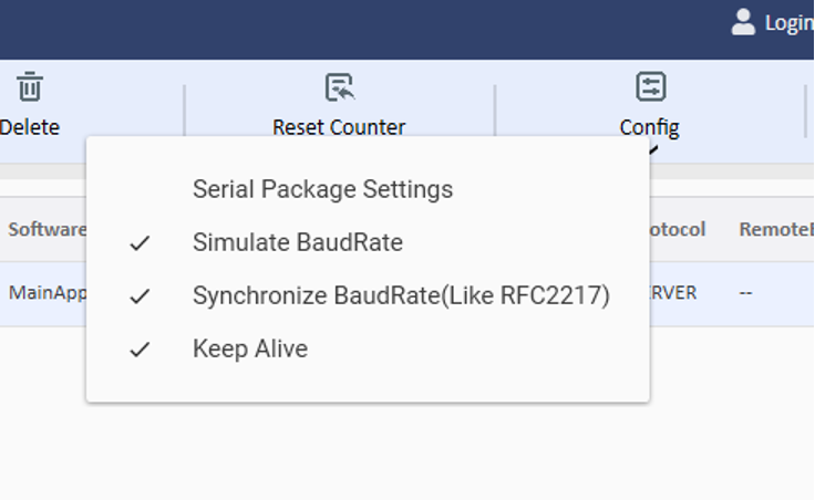
- Creating a virtual port on your computer
- Installing the SNET-Pro2 software
This will allow data transfer to your computer wherever it is located.
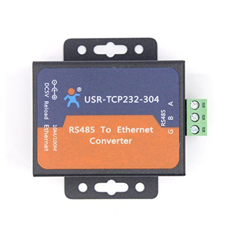
You can install any suitable RS485 to Ethernet adapter, but I chose the “Waveshare RS485 TO ETH” (low cost, good reputation) which can be purchased (Jan 2025) from Coolwell via Amazon for about £24: Waveshare RS485 to Ethernet Converter Supports Customized Heartbeat/Registration Packets,Webpage,RFC2217-like Protocol Available Client Modes TCP Server, TCP Client, UDP Server, UDP Client, HTTPD : Amazon.co.uk: Computers & Accessories.
This is one of the lowest cost adapters available, and the instructions below are based on this. There are other vendors of RS485 to Ethernet adapters that operate in a similar way, and while the exact settings are out of the scope of this document the same terminology is generally used, and this document may be a good base if you wish to use another vendor’s hardware.
Note that if running a single Ethernet cable between the RS485 to ETH adapter and the router is impractical (e.g. multiple walls to penetrate, or aesthetics considerations) then there are other options. The option I chose was a pair of power line adapters (PLAs) as I already had them. These plug in to the mains, one near the controller and one near the router – to convey the data over the house’s mains wiring. These are readily available from about £30 per pair. Thus the total cost of this option for monitoring would be about £55 – still far less than the MIM-C02N option. (However, note that PLAs may not function well - or at all - if they are not connected to the same consumer unit.)
If your controller is within wi-fi range of your broadband router, another option is to use a ”Waveshare 485_TO_WIFI_ETH_(B)“ to send controller data to your home Wi-Fi without need for the PowerLine adapters https://www.waveshare.com/wiki/RS232/485_TO_WIFI_ETH_(B). While the setup and configuration of a Wifi enabled version would be very similar, additional steps are needed to add the device to your Wi-Fi connection. Amazon sells these for about £39 (so cheaper than the PLA option if you don’t already have a pair). As I have not used this device I won’t be describing the steps to add this to your Wi-Fi. Maybe other forum users could contribute here…
I have written (with considerable guidance from my son-in-law) step-by-step instructions for setting up the Waveshare RS485 to ETH adapter in
Waveshare Install.docx (1.1 MB). These instructions include all the necessary software links, and assume also the use of a pair of BT PLAs and a BT router.
Note that the adapter set-up only needs to be once, and should not take more than an hour or so to complete. Once set-up, all you need to do is execute the SNET software whenever you want to do a monitoring run.
SNET-Pro 2 Effective Use
SNET-Pro2 is primarily of use to Samsung Service Engineers for commissioning and troubleshooting, but it can be very helpful to users to understand what makes their Outdoor Unit tick.
The User Manual can be found at https://s3.amazonaws.com/samsung-files/Tech_Files/SNET+Pro+and+SNET+Pro+2+Service+Software/Snet+Pro+Service+Software_SNET+Pro+2+Instructions.pdf.
I only have limited experience of the SNET capabilities but here are a few preliminary observations:
- The Home screen shows current values of several controller inputs (mainly instruments) and outputs (e.g. inverter frequency, EEV/SOV positions) updated every few seconds.
- The tabs near the bottom allow access to Outdoor Unit variables (mainly refrigerant-side) and Indoor Unit variables (mainly water side).
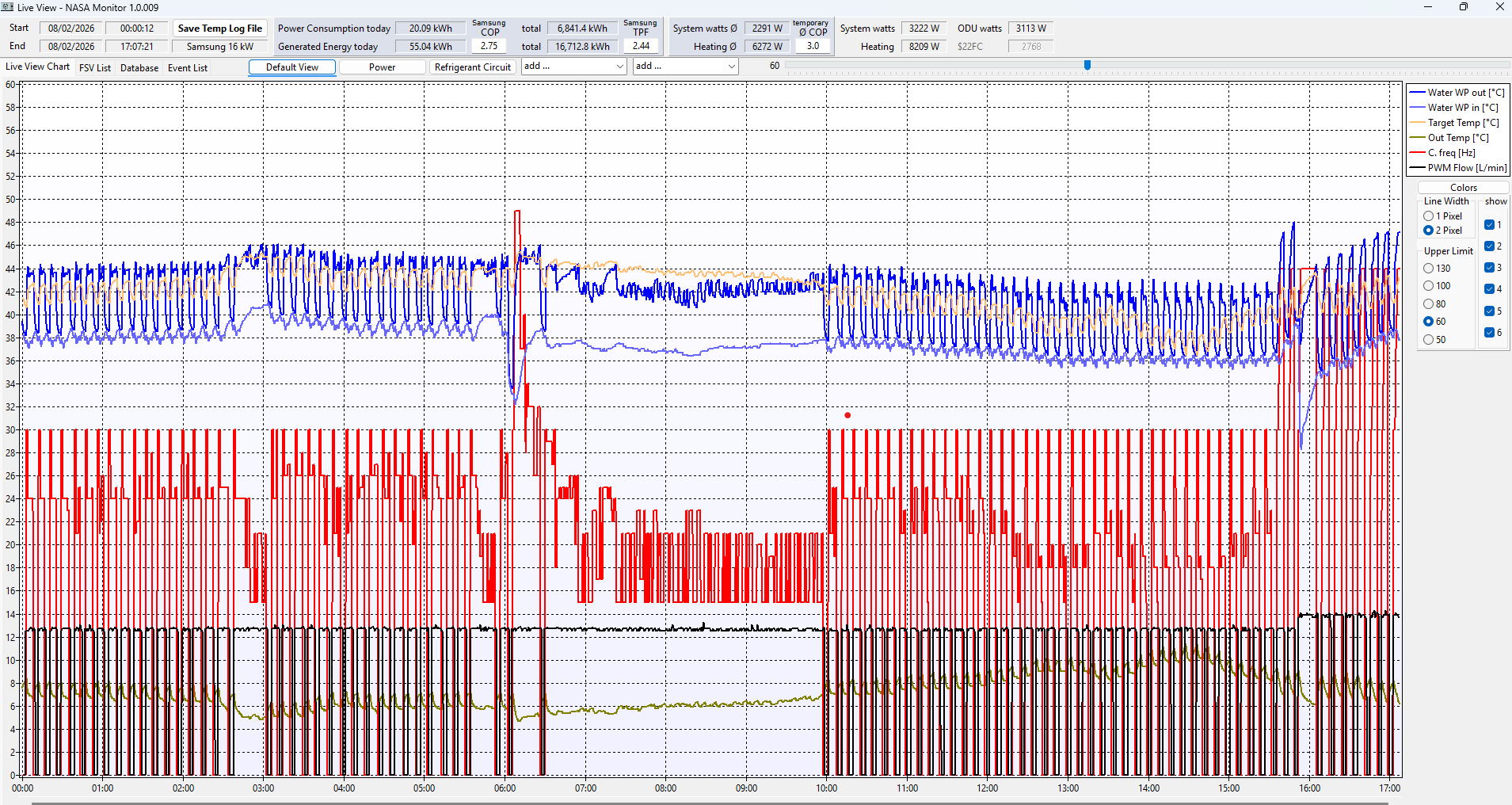
- The Trend/Graph tab allows you monitor selected parameters against time (though I have not used this yet).
- As soon as you start SNET, it starts populating an Excel spreadsheet at the frequency you set on the Options button. If you have the default frequency set (10s), this can quickly result in a very large file. If you want to suspend this logging, hit the stop/start button at the top of the screen.
- The spreadsheets are named by the time of start of monitoring, and are stored on your computer under Documents/SNET-pro2/RecordData with separate folders for each date that SNET has been used. This spreadsheet capability is very powerful:
- It allows you to trend one variable against another using Excel’s graph building tools (as opposed to trending only against time, as most OEM tools do). For example, you may wish to see how inverter frequency (i.e. compressor speed) affects compressor current (thus power consumed) in order to inform your decision on running in Quiet Mode (which runs the compressor at about 60% of normal).
- It allows you to add your own calculations based on the measurements. For example you could use LWT and RWT (reported on the Outdoor tab) and water flow (reported on the Indoor tab) to calculate the ASHP heat output at the time interval you have set in Options.
- It allows you to analyse various controller algorithms with a little reverse engineering. For example, you may see that the compressor recycle valve opens immediately the compressor stops (to equalise refrigerant pressures in the circuit, so preventing reverse flow through the compressor), allowing you to surmise that the temporary DT reversal in LWT and RWT seen following compressor shutdown may be due to flash cooling of liquid refrigerant in the condenser.
- The main downside of SNET is that it doesn’t show Outdoor Unit energy consumption, so CoP cannot be calculated.
When you examine the recorded Excel data, you will be presented with a screen like this (the data extends well beyond the screen – this is just the top-left corner):
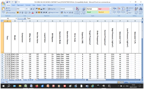
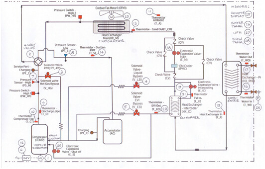
To help clarify what these columns mean, here is a listing of the Samsung headings (in their spreadsheet order), with my interpretation of what they mean (where not obvious) and references to their location on a marked up Outdoor Unit PFD:
SNET Interpretation.xlsx (12.8 KB)
(rely on this information at your own peril…). And here is the marked up PFD (strictly this is the HTQ version, but the other Samsung Outdoor Units have a similar PFD except that they have no intercooler/economiser circuit):
If you do install controller monitoring, please use this thread to share your experiences and correct any mistakes in the foregoing – I intend to keep the methodology evergreen, and (once road-tested by a few others) transfer it to the Docs page for reference.
PS – any owners of an HTQ Outdoor Unit who are intrigued by the principles behind the Samsung Economiser circuit could do worse than to read Economizers - SWEP and https://media.copeland.com/bd305da6-58d4-4db3-ac69-b16b0103f0c5/C071901_0208_0912_E_TI_Vapour%20injected%20Scroll%20compressors%20for%20Ref_0.pdf
Erratum: Just spotted a typo in the Waveshare Install document linked above. In step 4.1 “M0-Config link” should read “USR-VCOM link”. My apologies - a bit careless with my copy-and-paste ![]()