I wish. As part of my experimentation with this. I set the DHW off yesterday and wantd to test the Shelly Automation on the immersion heater. It worked a treat, lifted the DHW to 53 degrees and used less energy than the ASHP had previously. However as became clear rapidly I could see the thermal decline was much steeper than when the DHW was heated by the ASHP. So I ended up with a cold shower this morning as the hot water ran out very fast. I understand why and had clearly had a brain fart when testing it this way. The ASHP uses the massive Newark Cylinders Super Tank coil to heat the DHW from the bottom to the middle of the tank. This creates a better hotter column. The immersion just heats up the water from itself upwards and of course goes colder quicker. The ASHP DHW last much much longer. So it looks like that is the future for us and tested this morning the same shower router only dropped the ASHP generated DHW by .6 Degrees! Testament to the Newark Cylinders Super Tank thermal performance.
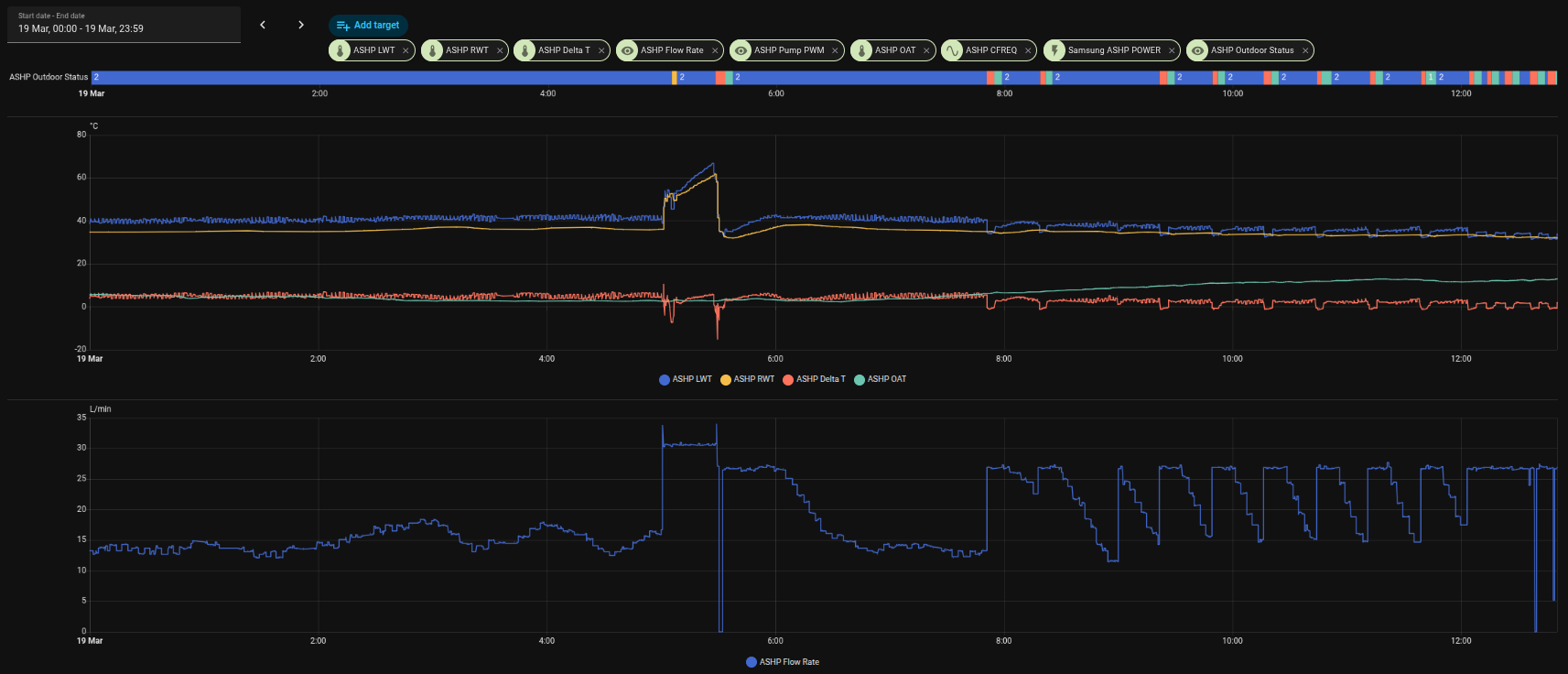
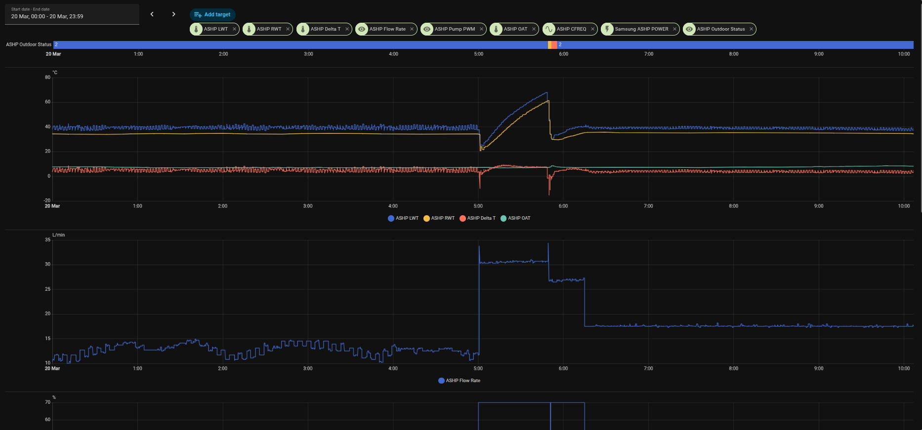
Today we have much the sme nonsense with the Samsung logic creating a degenerative cycle. I ran the system overnight and till 12:00 on the same -7 50 15 35 just to see if it did the same thing. It did! this whole cycle is created by the samsung flawed logic. On the graphs you can clearly see that at 07:50 the system started acting weird. The trigger a tiny change in OAT form 5.9 - 6.1 Degrees. The Comp went to Zero but catastrophically the pump went immediately to max output which then created a situation when the DT collapsed to negative 1.6 and then the cycle of boom and bust started. Had the pump just stayed bumbling along in the mid teens as it had done all night wiht a lovely DT of around 5 the rads would have had time to keep a healthy DT going.
Here is a technical analysis and the graphs. The pattern is very clear. The pump is racing the water around not giving the system time to shed the heat and returning almost as hot as it left or even hotter collaping the DT. Then the system realising it needs to reagain the DT fires up the comp again it panicks and pumps energy into the sytem it doesn’t by firing up the comp again using a lot of totally unnecessary energy into the system making the situation worse due to the overshoot. Now we have even more thermal energy in the system we have to get rid of. The RWT comes back high the DT collapses again. And around and around.
The root cause the Comp going to Zero on a very small OAT change and the pump going to max triggering a cascade and tanking the system COP for hours.
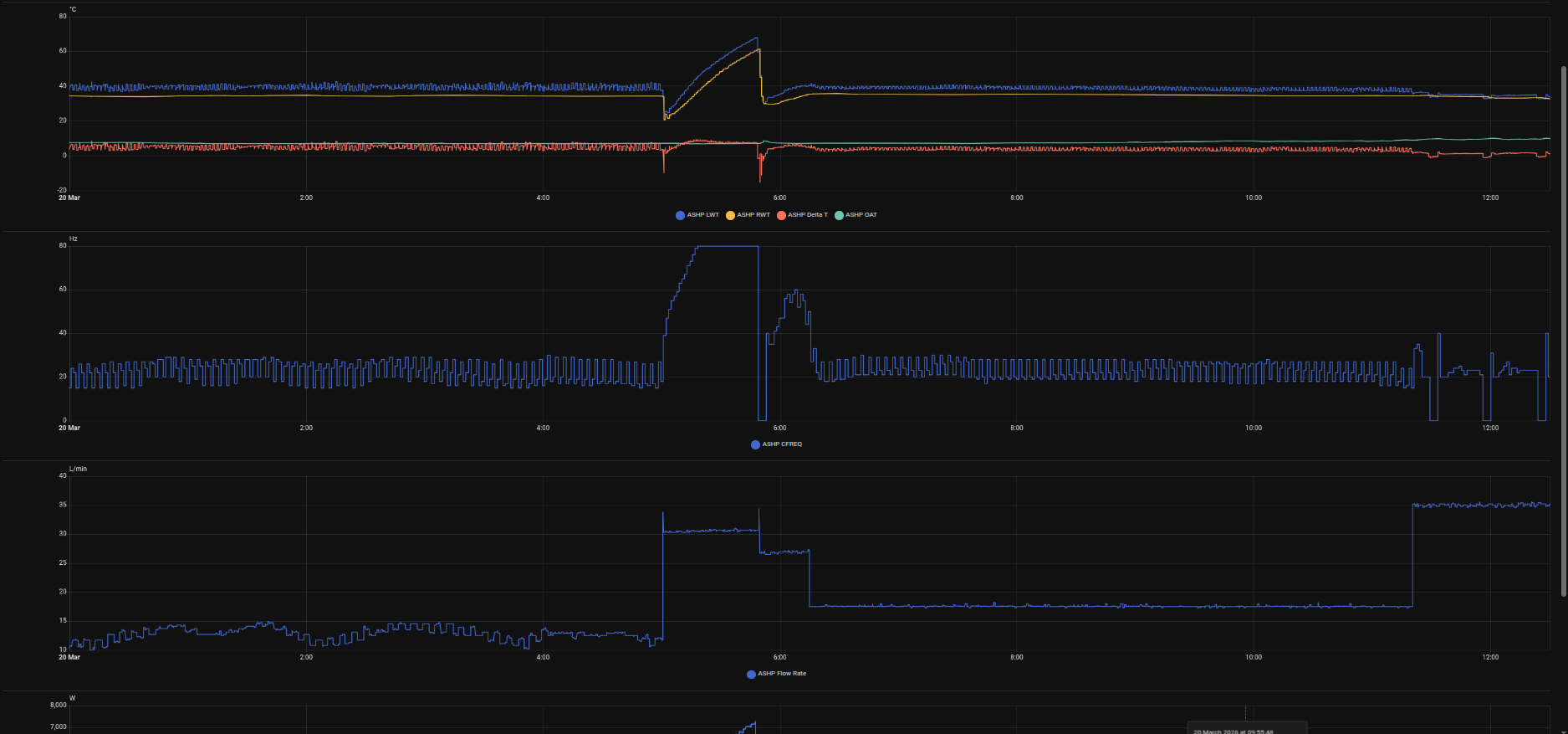
I changed the WL to lower the tail from 15 35 to 15 30 at 12:00 to try and stabilise the system for operation in a higher OAT. Here is a very graphic representation of the issue.
Why is the pump staying high? If it went back to bumbling along the RWT would drop and establish the DT without the need to pump more unnecessary energy in to try and create a positive DT.
I am sure there are more knowledgeable people on here that may have alternative explanations for the cause and effect and system dynamics. Any insights or feedback appreciated.
But if 2093 is set to 1 the Compressor never stops and should bottom out at around 15Hz, that’s what mine does anyway.
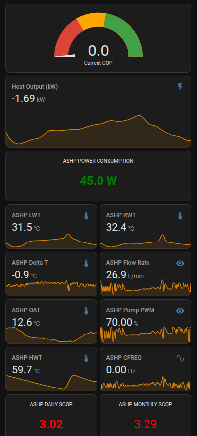
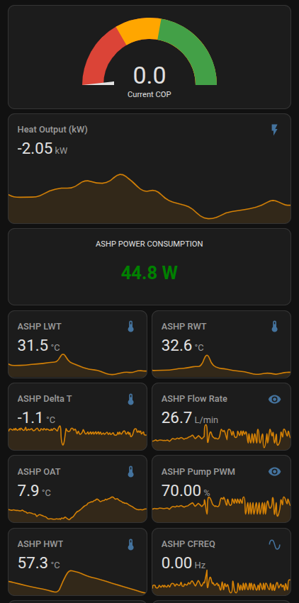
On a day like today 17 C, my ASHP Compressor sits at a steady 15Hz and the ASHP Fans fun at 390rpm which seems to be minimum for both devices and minimum output therefore for my 16kW Samsung ASHP.
This uses around 1kW of electricity and produces about 4kW of Heat power.
My ASHP is oversized and/or my emitters undersized, so what I see is a steady rise in LW from about 33 C steadily through the day up to around 39 C.
However I use my Wired remote as a system Thermostat and this is set to 20.5 C target setpoint, so when it’s exceeded, it just cuts everything off.
It kinda works for me, but I wonder why your Compressor completely shuts off if you have change that setting to 1 as it should just ramp itself down to a minimum frequency something like mine 15Hz.
You mean #2093 to 1 that setting is for when you are using the internal Remote Controller as the Thermostat we are trying to tune the system using Auto Water Law. Does 1 turn teh comp and pump off or just the comp?
It seems that 2 would turn the pump off when the comp goes off. 3 would leave the pump on when the comp goes off and 4 modulates the pump supposedly 7 off 3 on. that is not what we see in the data. The real issue is the pump is at max for most of the time and pretty much all of the time when the we are at thermo off and the comp is down. There does not seem to be any way to slow the pump down further which would sort out the DT issue.
This may only confuse things further, @antonical, but I tried to unravel some of the mysteries of the #209* settings in Samsung Gen 6 R32 5kW + Sunamp Thermino (plenty of questions inside) - #8 by SarahH.
You also asked about #4053 earlier in this thread. This is used by the MIM to continuously reset the circulating pump PWM using the following equation:
New pump PWM o/p (%) = Current PWM output (%) + [(LWT - RWT - FSV#4052) x FSV#4053)].
You’ve chosen to monitor WL temp not Room temp like me.
I’m no expert, I’ve only been playing with my badly performing system since mid February and it’s night and day how my system is now compared to the way it worked before that.
Fine, but your not using external Thermostat so I would say that #2091 and #2092 should be set to Zero or Off whichever applies.
However I would think that 2093 still plays a part in the control, even if the Thermo off is from Water Law temp or Room temp.
Just a quick update before I dive into Sarah’s unearthed equation. Settings #2093 to 2 did nothing the pump continued to run when the comp went down during thermo off.
Looking at that equation against the data then that is absolutely how the system calculates PWM except after restart when it jumps to 100% for a while. There must be some startup logic that takes precedence until some PIT when the formula takes over.
Todays run is a disaster zone. It’s not like it’s 25 degrees outside. Max OAT today has been ~12.8 degrees. This behaviour started at 07:50 when it was only ~6 degrees!
I am a little stumped as to why this system is not capable of operating in an efficient way at ‘normal’ UK temps. 3-15 degrees
Yes #2091 and #2092 are zero as I have no external thermostats. I haven’t tried that as it would involve moving to indoor temp control which is where we started with this system.
Right now I am gathering data to find the ‘sweet spot’ WL settings for the property and ambients. The weather has been changeable recently 1 degree to 17 degrees in a day and back again. But that will always be the reality with differing values.
This system has cycled 18 times since 12:00! The system was performing really well through the night when the OAT was low the pum pbobbing along in the low teens the comp also in the low 20’s all was good until the trigger at 07:50 with the OAT shift to ~6 degrees. Then the comp shut down the pump jumped to 100% and the nightmare began. With no real reason I can understand.
@antonical, @hank31980 is quite right in his analysis (and he is fast becoming an expert, no matter what he says…).
#2093 acts exactly the same as #2091/2, it just uses a different roomstat (the one in the Wired Remote Controller instead of a 3rd party roomstat). #2091/2 just give you the option of 2 different Water Law OAT-LWT lines, which you can select using #2081.
I really wouldn’t get too hooked up on #2093 = 2 or 3 or 4. As @hank31980 says, a value of 1 does have a dramatic effect on compressor switching - only your roomstat can do that in this case (though the circulating pump may continue to run for a few minutes even if the compressor stops due to the roomstat demand being satisfied). By contrast, a setting of 2/3/4 is much more likely to result in your compressor cycling, because the LWT target is typically reached quickly (maybe a few minutes) whereas your roomstat target is typically reached only slowly (an hour or more). So your choice of 1 versus 2/3/4 may have profound effects on room temperature stability (i.e. comfort), compressor cycling (mechanical longevity) and running costs.
Neither would I worry too much about tight control of (LWT - RWT). The (largely historical) rule of thumb of 5degC may have been useful for boilers, but there are good thermodynamic (and running cost) reasons for running to a lower number, and plenty of Samsung owners get good CoP numbers even below 2degC.
Concerning your later post about circulating pump PWMs, there is indeed a MIM algorithm that inhibits PWM control for several minutes after pump startup (30 from memory but check this!), so your observation is in line with this.
Finally, your rapid cycling is a sure sign that your LWT is bumping up against your Water Law target because your emitters can’t get rid of the heat fast enough. Unless you have a huge hysteresis on your LWT, the LWT will drop quickly and cause the compressor to restart, hence the rapid cycling. You really should consider setting #2093 to 1, at least during the “shoulder” months, as @hank31980 has been suggesting for ages…
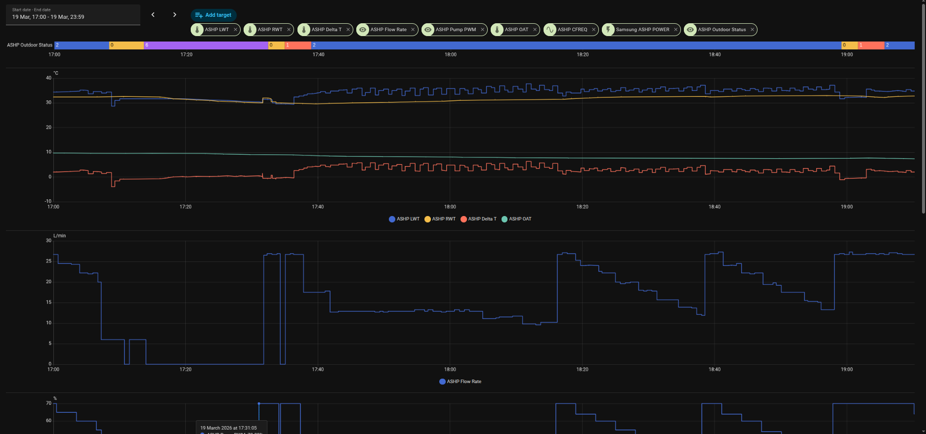
@SarahH many thanks. Yes I understand #2093. It is where we started this journey. For the past hour or so I have been manually stabilising the system by manually writing to the Pump PWM. Lowering the flow rate to get a reasonable DT. I am pretty much there although I can see I have reached a kind of floor where the LWT whilst ~target still has RWT climbing very slowly. I can’t modulate the pump down any further without E911. As soon as I give control of the pump back to Samsung then cycle city..Although OAT is coming to my rescue fast as its now ~8 degrees so back into manageable territory for the unit.
Your comment “Finally, your rapid cycling is a sure sign that your LWT is bumping up against your Water Law target because your emitters can’t get rid of the heat fast enough.” The reason they can’t get rid of the heat fast enough is that the Pump is running at max! Whizzing the warm water around and not giving the emitters time to do their job. I stabilised this system within a few minutes of manual control. The unit had been ‘trying’ for over 5 hours. When I gave control of the pump back to the unit it took it about 40 minutes to collapse the DT by consistently running the pump at too high a flow rate and triggering a comp off cycle. The OAT is 7.7Deg.
As an engineer I am always looking to understand the dynamics and complex interactions of the various sensors and system characteristics. It is clearly a learning curve, I am pretty sure there is a WL curve that will work across a normal temp range for this property.
Going back to room temp control feels like a retrograde step (it wasn’t very successful when we started out) when in theory there should be a much better way of balancing the system with the OAT and comfort levels. This is a journey we are at the start. Thank you for your assistance, not ready to give up just yet.
Heres a picture of me vs Samsung. Stabilised then Samsung slowly crippled the system and triggered a cycle. It’s still trying to stabilise it but with the pump at 100% it has no chance. My other option is to give it some more headroom by lifting the curve up 1-2 degrees.
I have Silent Mode enabled between 22:00 & 06:00 just to limit the Compressor frequency (therefore noise level) in the middle of the night, in case my system kicks in.
I too have selected PWM of 70% via one f the FSV’s and this seems to work well, I run with a Primary ASHP flow of around 12.5 l/min. I think I should probably try and improve this, but Im more interested in the system just working for now.
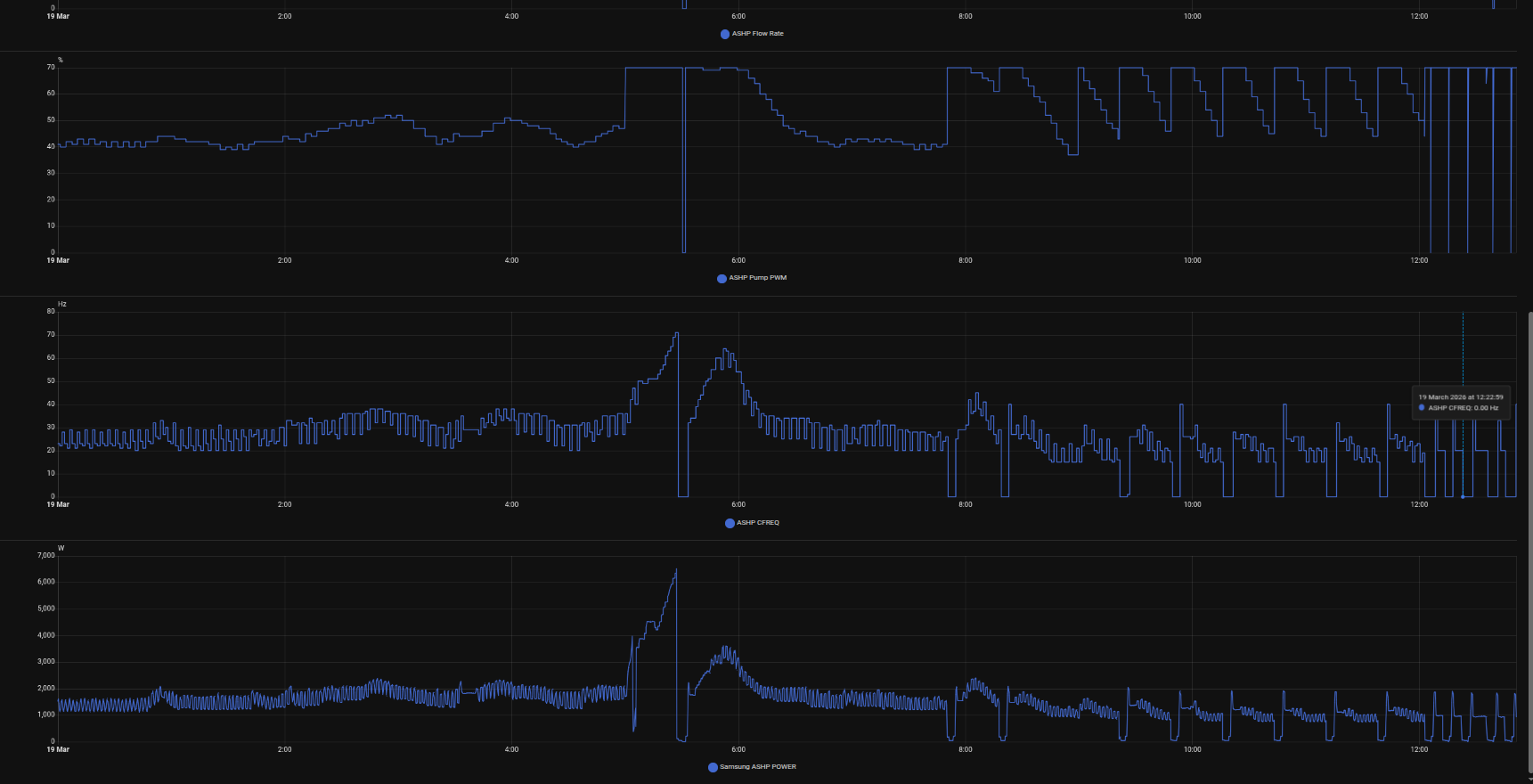
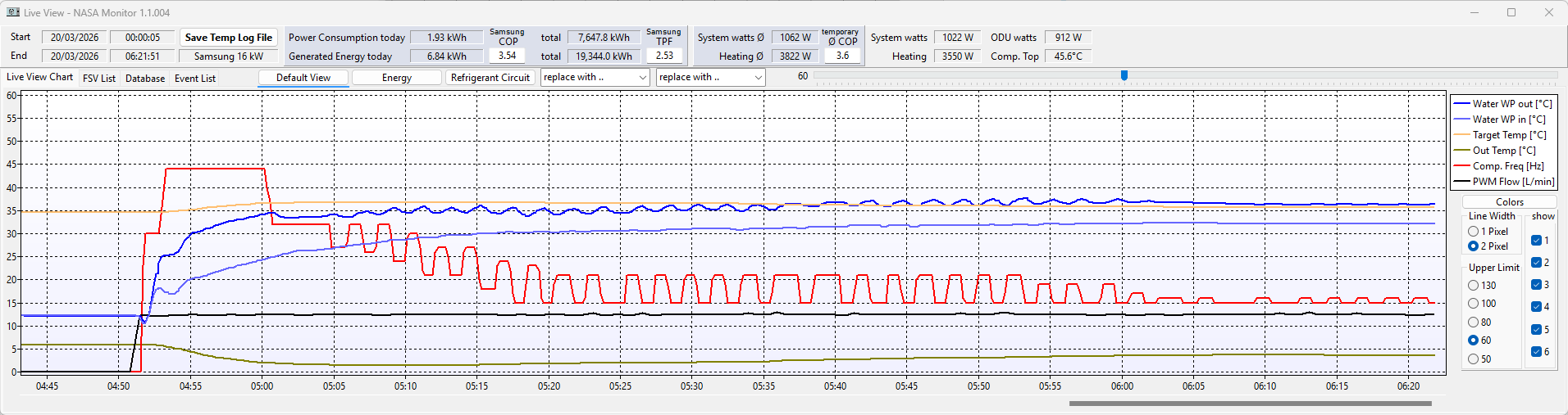
This is my system starting at around 04:50 this morning, RED line is Compressor frequency, so you see it initially spike for about 10 minutes then gradually start to drop back. It has some oscillations, but the general trend is going down.
You can see that the LWT & RWT “BLUE lines” are doing and you can see that about an hour from cold startup, I’m operating a little above the WL setpoint “YELLOW line”.
However the system is happy and just keeps chugging along, but if you notice, the Compressor frequency keep dropping back as does the Fan speed and I know will eventually become a flat line sitting at 15Hz, same as the Fan speed sitting at 390rpm.
Because of my poor system design (ASHP oversized & Emitters undersized) then during the day, the LWT keeps gradually rising and will most likely end up about 4 or 5 C above setpoint, but my Internal Thermostat will eventually exceed Room setpoint and switch everything Off, allowing LWT & RWT to dissipate heat and maybe 3 or 4 hours later, the Room stat will call for heat and the whole process repeats.
Its not perfect, but for now, its stable and I have time to think about improvements.
Right now it sounds like your in the eye of the storm, fighting to get the system under control but our suggestions about #2093 I think is the key to bringing some calm.
No, the reason they can’t get rid of the heat is because they aren’t large enough for the LWT you are running at.
Think through the cycling mechanism by way of an example:
If your HP can’t deliver less than say 4kW even at minimum speed, and your rads can only dissipate say 3kW at your LWT setting (i.e. your Water Law target), then that surplus 1kW has to go somewhere, and it goes into heating the circulating fluid system.
Because the latter is fairly small, LWT will rise rapidly irrespective of circulation flow rate. Once LWT exceeds WL target by ~2degC and assuming the compressor is already at minimum speed, the controller has no option but to stop the compressor (but keeping the circulating pump going). Once the compressor stops, no heat is going into the circulating fluid system, but the rads are still emitting the 3kW, so the fluid will rapidly cool, again irrespective of circulation rate. And once the LWT has dropped ~2degC below WL target (assuming you have the default hysteresis), the compressor will restart.
To stop this cycling you need to increase the radiator heat output (i.e. increase the 3kW in the above example to the minimum HP output of 4kW). You can do this by installing more radiator area, or (far easier) by increasing the LWT. And you can do this either by increasing the WL target (using the +/-5degC offset on the WRC, or by increasing #2021/2), or by setting #2093 to 1 (which inhibits the compressor from stopping if LWT reaches WL target, and allows that surplus 1kW to increase the radiator temperature until the radiators can dissipate the full 4kW.
All this has little or nothing to do with fluid circulation rate, and yours (~15-30 lpm) should be quite reasonable for your HP output duty (~4-16kW).
@hank31980 found that the #2093 = 1 option settled his system down as a first step, and allowed him to optimise his WL settings as a second step. You might find this too…
I wrote an automation last night to modulate the pump down after a restart to avoid yesterdays nonsense.
Here is the result! My automation took over at 06:14 following the DHW cycle and what would have turned into exactly the same behaviour as yesterday. By modulating the pump down the system was stabilised within a few minutes and a healthy DT established and comfortable property. I manually added 4 degrees last night to get the property comfortable then left it to see what would happen. The underlying WL is -7 50 15 30 +4 Deg on the controller. I deliberately set the DHW cycle for 05:00 - 06:00 just to see the recovery as the OAT are rising. It is back to 03:00 - 04:00 from tomorrow.
The data doesn’t lie. Its a picture of health. I am sure I can tweak it further but right now I can’t find the Modbus register for setting the Water Outlet Temp for a Gen 7 Integrated unit. So if anyone knows what it is and any other hidden or changed registers I would appreciate it.
Well done, @antonical.
I rather suspect that it was your setting the WRC WL offset up to +4degC that did the trick. I was pleased to see that your system stability before and after your DHW run was equally good, despite the water circulation rate changing from ~12lpm (before) to ~18lpm (after). This supports my assertion that circulation rate has (within limits, obviously) little if any effect on stability.
@SarahH to your points I understand the principles. However the empirical evidence from this exercise is that on our system; maybe someone else’s is different, what happens in reality is the Samsung keeps the pump at ~max and that leads to a rise in RWT that collapses the DT the Samsung panics because it has a target DT and pumps in a load more energy to create a positive delta. Then the pump keeps running at max and the cycle repeats getting gradually worse raising the system temp and to your point making the problem unsolvable unless the system is given head room to recreate stable running.
I watched it happen in realtime. We had already set the pump to 70% max rate overall last week. It was better but not by enough to create stability except when really cold outside then it was somewhere in the vicinity of stable with a lower amplitude of change.
Modulating the pump down immediately gave the system time to do its job and radiate the heat. Radiators are not magic then need time for the thermal flow to offload the heat if you are speeding through them they do not have enough time to do that the RWT returns high and the Samsung then reacts to try and maintain a positive DT. How do I know this? The RWT stopped climbing and the DT was restored quickly LWT was also stabilised ~set point Reaching a balance point quickly. Right now its a pretty dumb automation that once stabilised gives control back to the Samsung to manage the pump, it does but on the high side with RWT rising, but a lot more slowly.
That is the reality of our system, it is what we see in the data and feel in the environment.
What we should be able to do is run the system at auto with water law as low as we can go and still maintain a comfortable property. That looks like is it somewhere around 15 34. There is no way I believe I know more than the Samsung engineers who build these things with decades of experience in the market and probably hundreds of millions of hours of telemetry. I am not delusional!
What I am trying to do ITRW is to solve a problem using whats available to me. I have successfully stabilised the system at the expense of constant Comp modulation. The comp oscillations are what is now stabilising the DT and the environment. Not good for the long term. Great for the house environment as it is lovely and stable with a nice temp throughout the property.
BUT all I have really done is cured the symptoms. Not really an answer. Maybe we need to look at the system design, although we are limited in what we can do. Volume is ok, rads are correctly sized and balanced using a thermal imager, we can’t really change the building fabric any more than we have. This is an interesting challenge, sorry if my posts have annoyed anyone. Just in search of the ‘answer’.
The system in engineering terms was not really stable before or after worse before as the comp amplitude was bigger than after but still pants. Look carefully at the Cfreq its bad.
Auto managed it should have found a stable hz and we should see a much lower amplitude oscillation in the comp and flow rate. The right hand side cycling is due to changes Samsung wanted me to log for today. So the system is now set to 15 30 with no offset Inverter pump PWM 100% The house is already colder and the stability gone. Hey ho. Lets see where we go.
Your compressor speed stability is actually pretty good! The inverter is staying within ~18-25Hz (that’s quite a tight range compared with others I’ve seen), with a cycle time of about 4 mins, and this is keeping your LWT rock steady at 40degC, which I presume was your WL target. So your rads will have been delivering a nice steady output, at least until about 11:15. What exactly did you do then to upset this stablility?
…I should maybe have added that inverter modulation over a modest frequency range (like you had until ~11:15) is perfectly normal, and doesn’t count as “cycling” (so definitely isn’t shortening your compressor life). Indeed, it says to me that your WL settings are pretty much ideal for the current OAT at least , so you should be rather pleased with your progress to date. If you aren’t, perhaps you could clarify for us what’s still troubling you?