Did you see my post about the maximum value on the heat meter? Is that an “all time” maximum?
I’ve been looking at the Supercal 531 manual just now trying to figure it out. From what I can tell, the “Average” and “Maximal” values for the the current time period, and you can increment through 32 previous periods.
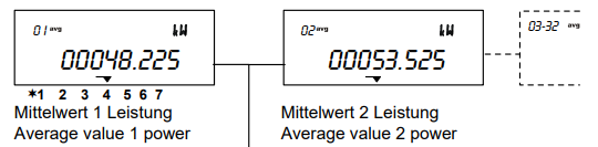
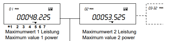
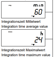
The period is defined in the configuration menu, and the default looks to be an hour for average and a day for maximum. Maybe you can sync these up to Melpump readings?
If you’re tempted to hook this heat meter up to the Ecodan, beware a problem I had with mine:
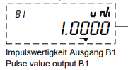
Mitsubishi have a dedicated unit that they sell that sends 1 pulse per Wh. My installer fitted one from another supplier which could only count whole kWh, which was useless for real-time monitoring. This could not be reconfigured in the field, and was replaced with an official unit.
I don’t know how to tell which one you have. Maybe this screen of the configuration menu?
Thanks Tim. Ill have a good look through this when ive a bit of time. Really helpful. ![]()
@bontwoody and post #56
Hi Mark ,
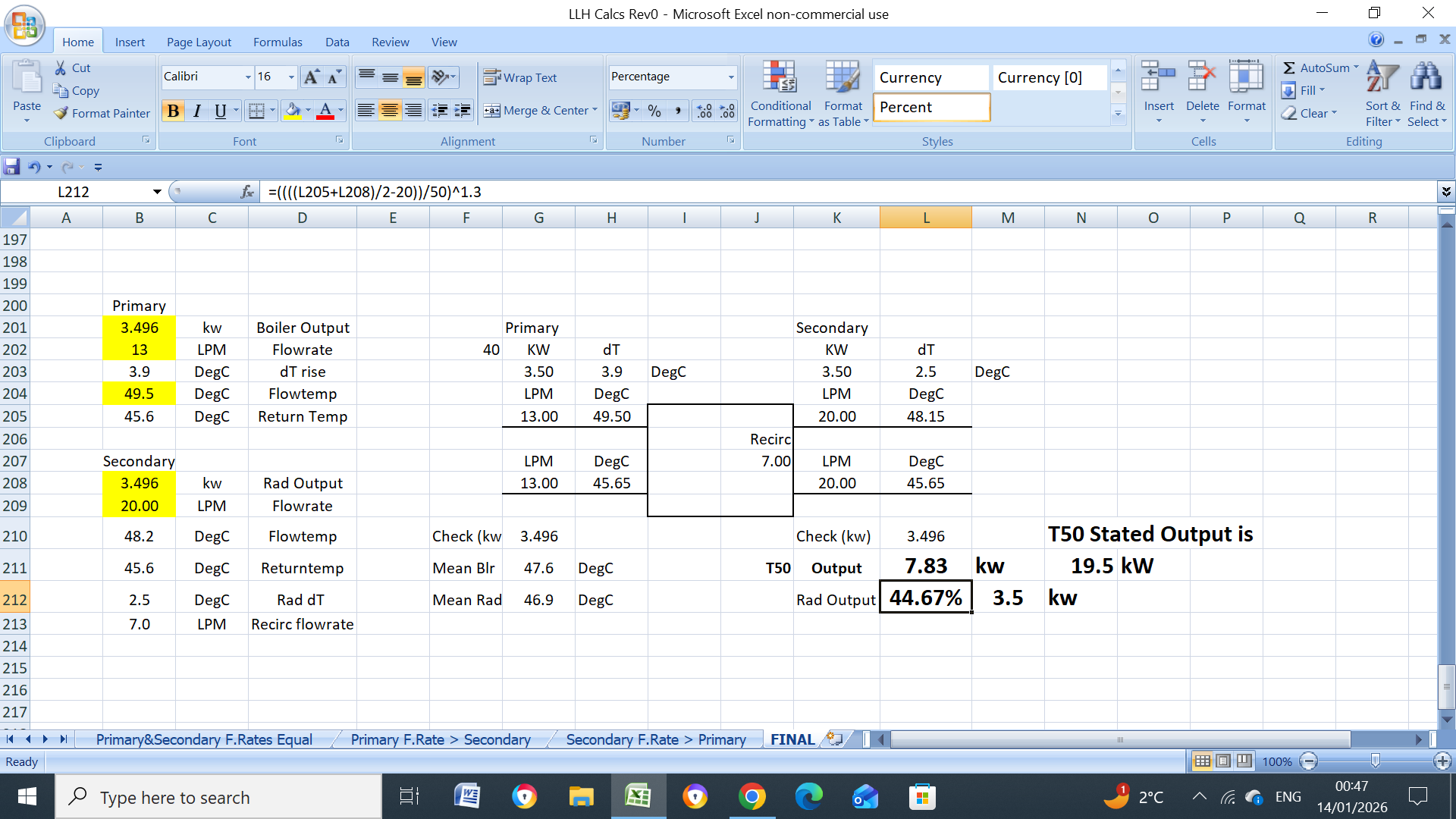
Re above , If the actual flowrate is 13.0LPM with flow/return temps of 49.5C/45.5C) dT 4C and the output is 3.4kW then the T50 rating of the rads in question just cannot be 19.5kW, I used water only but this doesn’t really distort anything, it only gives a slightly higher output of 3.6kW. The mean rad temps are (49.5+45.5)/2, 47.5C, at 20C roomtemp results in a, 47.5-20, 27.7 deg rad with a output of (27.5/50)^1.3, 46%, which means that the T50 rads “in question” can only be, 3.6/0.46, 7.83kW, or 3.4/0.46, 7.39kW (glycol). The HP specification, post #34, gives a flowrate of 40.1LPM at 14kW, which equals a dT of 5C (water) or ~ dT5.4C (glycol), the primary pump is running at full speed yet this only results in a apparent flowrate of 13.0LPM, strange?. Anyhow, enough said for now.
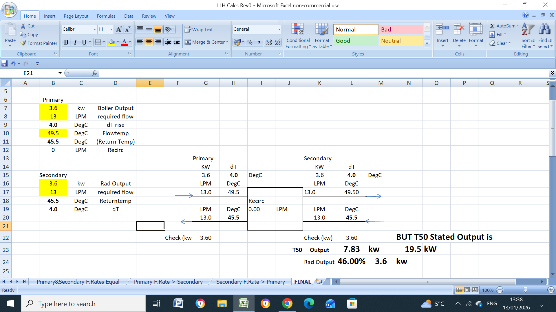
I agree with John’s maths. When the heat pump is running at a stable temperature at it’s lowest power, the flow temperature settles at the minimum that the radiators can output. When the emitter surface is only rated at 7.39 kW, that minimum (mean) flow temperature is 47.5°.
If the emitters really were rated at 19.5 kW (and assuming that all measurements are accurate), the (mean) flow temperature would settle around 35°.
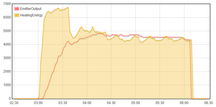
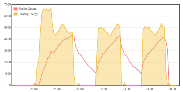
Below is a plot of heat pump power vs emitter output for my system. When the heat output (yellow) matches the emitters (red) we get stable running. If emitters can’t match heat pump and the flow temperature exceeds the target, we get cycling (like 2nd chart).
So, the puzzle for your system is why the apparent emitter size is smaller than expected:
- measurements could be wildly inaccurate, leading to wrong conclusions
- one or both pumps could be running too slow, unable to shift the heat into rads
- radiators could be constrained too much, not allowing enough flow
- some other heating system fault we haven’t considered
Oh, a quick note about measured flow rate: I have noticed that the flow rate reported by Ecodan is calibrated for water, and does under read by a couple l/min when glycol is present. So your 13 l/min might actually be 15 l/min.
Thanks for the explanation both ![]() I think I get it now.
I think I get it now.
Ive just gone back and double checked the radiator outputs to be sure they were at DT50 and not DT60. They are so thats not it. They all do have TRVs and Ive left instructions for them all to be left at max, but I think I need to check they are, as well as the Lock Shield valve settings.
If the primary pump is running at 13 l/min flat out then maybe I should try speeding up the secondary pump which is on setting 1 at the moment? There is about 30m of 28mm copper pipe connecting the LLH from the outside unit through the bungalows loft. Do you think the primary pump is powerful enough?
Any other ideas on things I could try? Thanks again both for all the time you are spending on this.
To give another reference point, with the caveat that every heating system is different, my system (see post #11) has about 20 meters of 28mm pipe between internal and external units. The pump speed is set to 3 in FTC for heating (limited for noise reasons), 4 for DHW. Flow (when heating) is measured to be 9 l/min (inverse of mass flow formula gives 11). The secondary pump is set to speed ‘I’ - have no idea what this means or if this is optimal.
My pumps are different to yours (and to each other):
- Primary: UPMXL GEO 25-125 130 PWM
- Secondary: UPM3 AUTO 25-70 130
I note that your two pumps are the same as each other (UPS2 25-40/60 130), and neither has PWM so maybe not controlled by FTC after all? I don’t know about heating pumps to advise any further.
Anyway, with a similar sized heatpump, emitters, pipework and flow rate, I seem to be able to run at 40° no problem.
Here’s another 14 kW Ecodan with similar heat demand of 8kW, running as low as 30°. Note the higher flow rate (28-30 l/min) and tighter dT (2°) when at minimum power. Heatpump app calculates emitter size to be 30 kW across 2 zones.
Here are some other forum topics that may contain useful information:
- Ecodan pump speed settings (particularly post #9)
- Using ESP to control pump speeds via PWM
Thanks Tim. If I understand the numbers properly that means your primary pump is twice as powerful as mine with a head of 12.5m. I wonder if thats significant/ Although your flow rate isnt significantly different. If they did have PWM maybe all the fuss over flow rate would disappear ![]()
When I was last on site, I noticed by touch how much cooler the secondary pipes were than the primary. Could the temperature loss across the LLH be so great as to account for the low output from the radiators?
These are interesting thanks
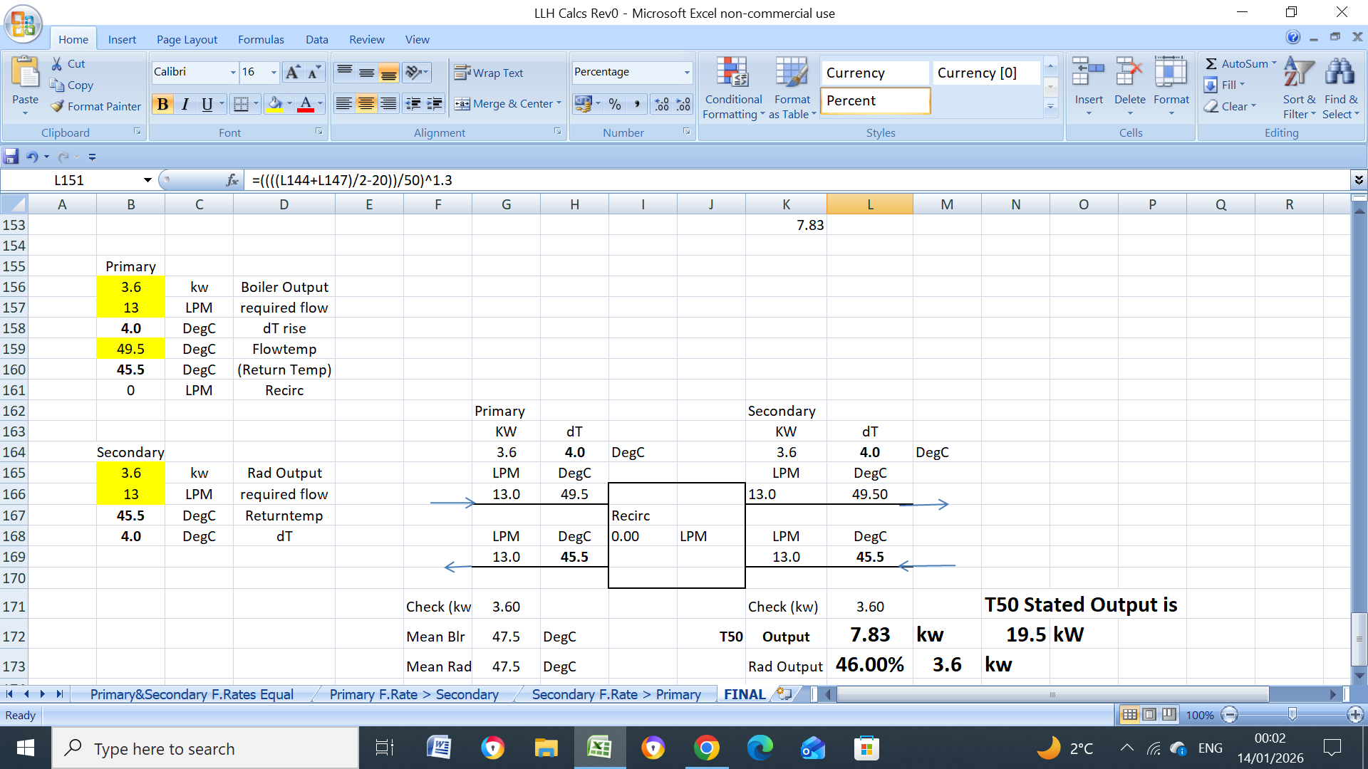
If the two flowrates are the same at 13LPM each then you can see the effect second below (assuming water), the output is 3.6kW with a rad return of 45.5C If the secondary (rad) flow was ridiculously low at say 3.15LPM then the rads return will only be a pretty cool 36.5C (see immediately below) with a rad output of 2.86kW.

1 Like
As John’s spreadsheet shows in post #15, either the top ports are the same temperature (when secondary flow rate is <= primary), or the bottom ports are (when secondary is >= primary). The secondary side cannot be cooler at both ends of the LLH. However, the mean temperature can be cooler on one side, which will directly affect the emitter output. If you’re able to measure the temperatures at the 4 points, that could be useful.
Probably a red herring at this point, but did you feel the pipes on the DHW side?
Correct, also, if the secondary flowrate is increased to 20LPM vs primary flowrate of 13LPM, then the output changes very little, 3.5kW vs 3.6kW, its surprising really how a very big increase in secondary flowrate has such little effect on the output, assuming calcs are correct.
So it sounds like I should try increasing the secondary pump speed as it cant do much harm ![]()
I did feel the pipe on the DHW side but it didnt feel hot. I ve just ordered 4 temp probes so Ill check that as well as the LLH pipes.
1 Like
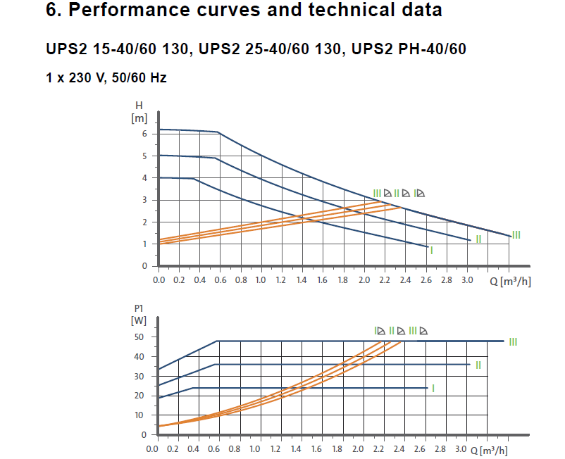
If you really want to get a fairly good handle on the pump’s flowrate/performance/system/HEX resistance etc you can buy a cheap as chips energy monitor like mine, below, and connect it in between the pump cable and its suppy (or any supply), UPS2 isn’t the easiest to derive the flowrate from the pump curves as it reaches full power quickly on whatever setting you are on, for example, if its pumping 13.0LPM, 0.78m3/hr, then its running at 5.6M head at ~ 47W but you don’t know where on the curve you are, but the pump performance can easily be derived by changing to PP (proportional pressure) mode, if the pump is running at 47W in (its present CC mode) 13lpm, 5.6M, then in PP3 mode it will circulate 6.7LPM (0.4m3/hr) at 1.5M & 8W, I’ve used this method quite a few times for trouble shooting, maybe worth a go.
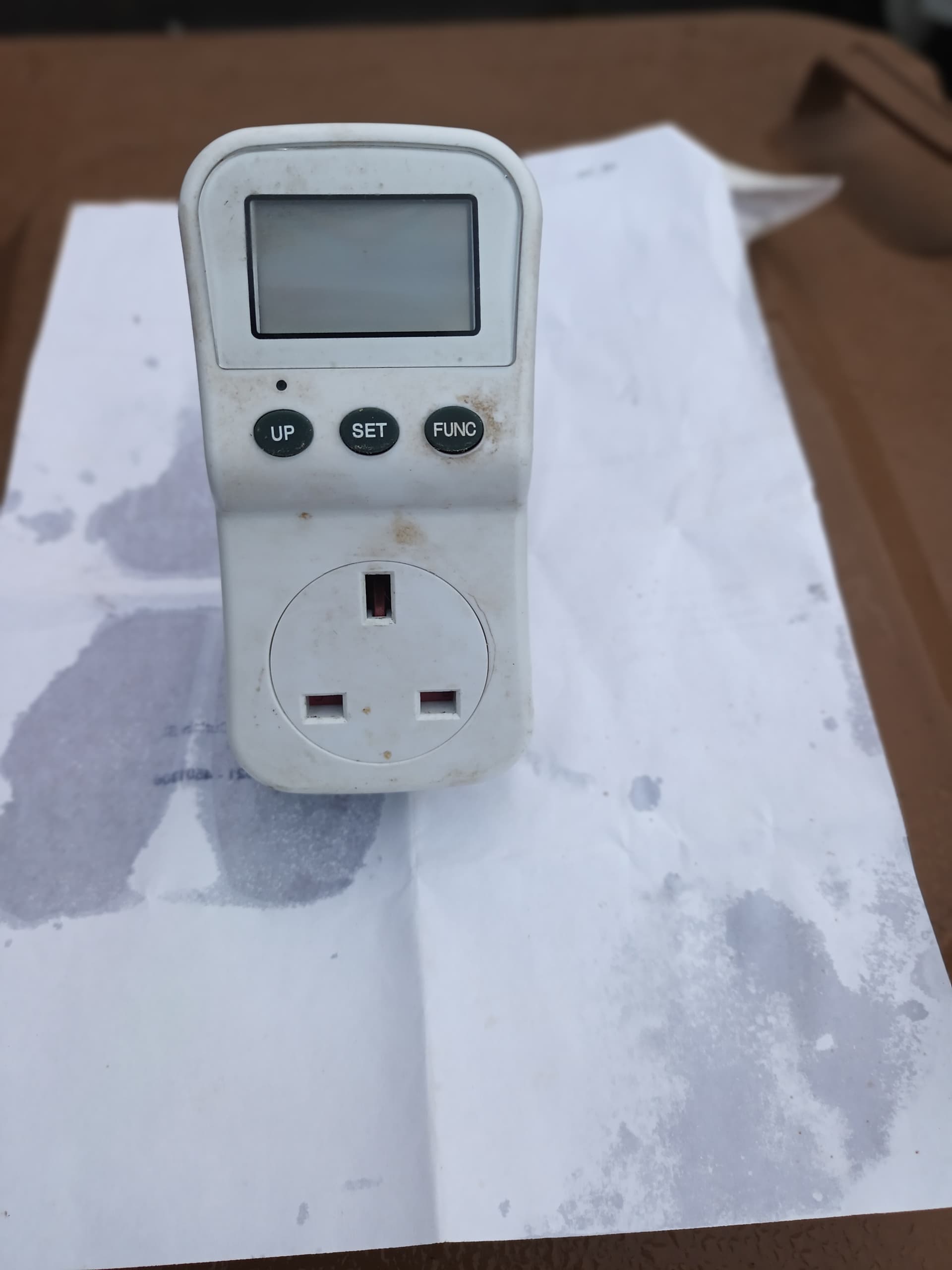
Thats useful to know. As its not my installation, I would be reticent to cut any cable to attach a plug to the pump but I guess I could do the same thing with a clip on sensor
Probably not. If it is single wires (L-N-E) then yes, put your c.t. on the L, but if it is a multicore cable, then a c.t. will not work.
Clip on sensor won’t work as it doesn’t measure the power factor.
Attached is a spreadsheet showing that the effect of different (unbalanced) flowrates dont make a huge difference especially at those very low outputs, you can play around with it yourself, if interested. Its based on water but doesn’t make a whole of difference.
LLH Calcs Extract Rev0.xlsx (17.5 KB)
1 Like