I was wondering if anyone has gotten to the bottom of the Ecodan FTC’s ability to control pump speeds.
Ecodans rely on external circulation pumps. There are settings in the service menu for pump speeds for heating and DHW. On my system changing these doesn’t do anything.
I’m assuming on the Ecodan pre-plumbed cylinders this does work?
If it does how does it work? PWM or some other way?
Is there any way to get this working with other pumps?
I wouldn’t be bothered if I just needed a single pump speed as I can just set this on the pump but I am wondering about experimenting with different speeds for the heating and hot water as the circuits are very different I would have thought there would be benefit in the ability to have different speeds.
Anyone have any experience of this?
Thanks @MyForest that is interesting but my problem is more fundamental than that.
Changing the speed setting on the FTC6 controller doesn’t actually seem to change the pump speed.
How are your, @mjr and @Rachel pumps connected to the FTC?
My pump has its power coming from the FTC for in and off but has a separate PWM cable that isn’t connected to anything. I can’t work out how the FTC varies pump speed (when it works).
My main pump seems to be connected only with a power cable, but I didn’t wire it and haven’t checked the markings, so that cable might contain more cores for all I know. It has its own on-pump speed control buttons.
I can’t figure out what the FTC5 pump speed setting does, if anything.
Hi Andrew,
yes - sort of! I got interested in the pumps, because my system tends to have a low temperature drop through the radiators, so I figured that dropping the flow speed would be a good thing to do. I found that it was a bit more complicated than that.
I have an Ecodan with the Mitsubishi pre-plumbed standard cylinder. I have 3 pumps, one of which can be changed from the FTC5 controller.
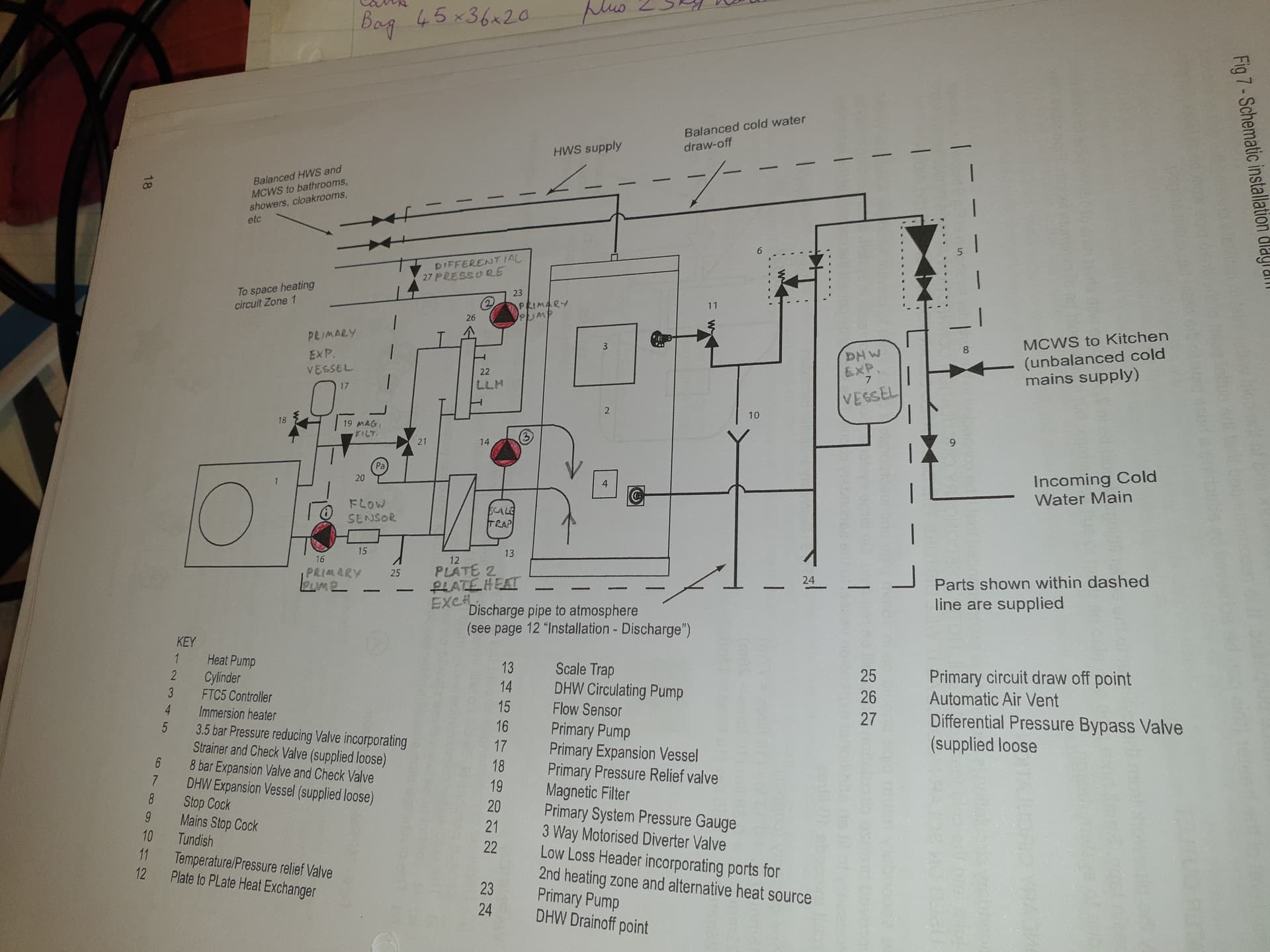
I found the manual for the cylinder very informative. Having studied it, I finally understood what all the spaghetti on the cylinder was actually doing, and why there are 3 pumps.
Here’s a schematic of my system…
Grundfos UPM GEO 25-85 130 which pumps the heat pump primary circuit
Grundfos UPM3 AUTO 25-70 130 ZZZ which pumps the radiator circuit
Grundfos UPS0 15-60 CIL2 which pumps the hot water circuit
My primary pump has both a power cable, and a separate pulse width modulation cable from the FTC5.
So if I navigate through the menus on the FTC5, to alter the pump speed setting between 1 and 5, then only this pump is affected.
My other pumps only have power cables. The hot water pump has 3 possible speed settings, which can be selected using a switch on housing. But my cylinder manual says that it should be set to speed setting II to ensure optimum DHW heating performance, so I never tried altering that.
The setting on the pump on the radiator circuit can also be adjusted manually, by pressing a button on the front of the pump. This has at least 10 possible modes.
It was at this point that I twigged that my system has a “low loss header” (which explained why I have 3 pumps). I have watched the videos on the Heat Geeks website, but I still don’t really understand why my system has a LLH. All my rads are on one circuit, and there’s no under floor heating, so I don’t really understand what good it does. As far as I can see, it just makes the system more complicated, and potentially less efficient. eg. if the pump on the HP circuit is on full power, but the rad pump is on low power, then most of the flow from the HP can take a short cut through the LLH, and go back to the HP return without ever seeing a radiator. This doesn’t sound like a great idea to me. Conversely, if the HP pump is pumping less flow than the rad pump, then the return flow from the radiators can take a short circuit through the LLH. There it will mix with the weak flow out of the HP, and drop the temp of the flow going to the rads, which also seems like a bad idea to me.
As far as I can see, for my system, the ideal would be to balance the HP pump and the rad pump, so that there is zero flow taking a short cut through the LLH. In the end, I fitted 4 thermometers (1 on each the 4 pipes connected to the LLH), and recorded them on the OEM system. I set the HP pump to 5 on the FTC5, and then messed around with the rad pump settings until I found one which gave HP flow temp = rad circuit inlet temp, and HP return temp = rad circuit exit temp. Then I repeated the experiment with the HP pump on setting 4 etc. Whilst doing all this, I was also trying to measure the COP. The variations in the COP were not huge (roughly 10%). But they seemed to peak when the temperatures across the LLH were balanced. It was all a bit time consuming in the end - and my initial idea of just tweaking the pump speed on the control panel seems quite naive in retrospect.
I don’t like complexity for no reason, and I don’t really see what the LLH contributes to my system. To be honest, I reckon the design of my whole system is rubbish. I am thinking about draining it down, fitting larger K3 radiators downstairs, anti freeze valves, and bypassing the LLH completely.
My installer couldn’t get stock of an Ecodan cylinder so sourced a different cylinder and reading this I’m glad they did as they’ve set it up with a single pump and no other complexity like LLH.
I vaguely remember reading somewhere that it might be possible to not plumb in the LLH on the Ecodan cylinders but not sure how that would work if there are multiple pumps.
Do you know where the PWM cable wires in to the FTC5?
I have always believed that the software adjustment is only for adapting the pump speed to the system hydraulic requirements. I don’t think there is any feedback control (dt etc) to vary the speed to adapt at any one point in time. Maybe on FTC7?
Yes it is just a fixed value set at the controller but the main advantage from being able to set it is that you can have different pump speeds for heating vs DHW.
However I still don’t know how it can actually be set up to work. Hoping someone who it does work for can let me know how their pump is connected.
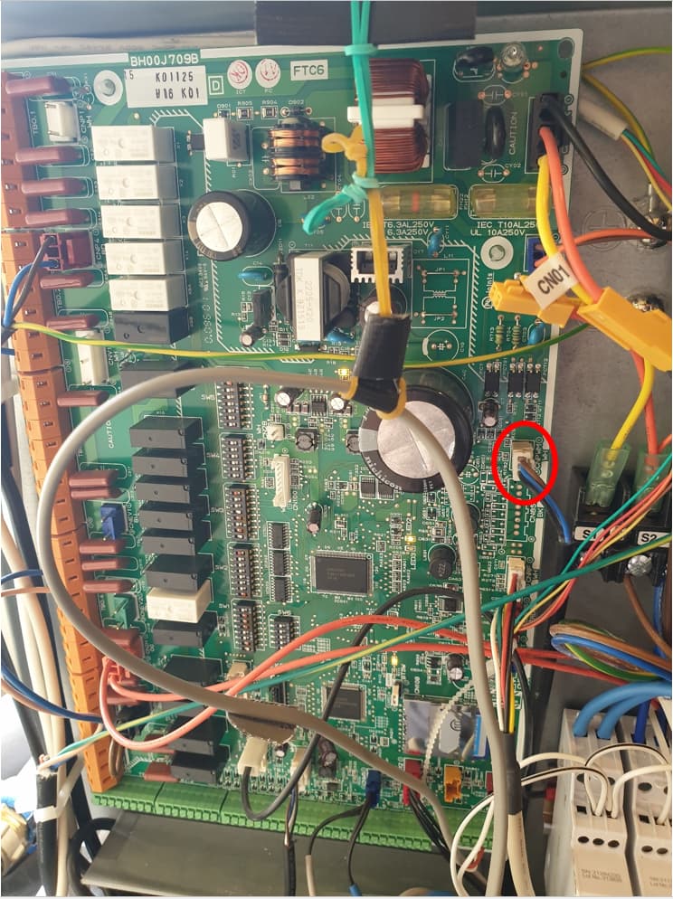
Here’s a photo of where the PWM cable plugs into my FTC5 (I’m 99% certain this is right, but my installer doesn’t seem to have shortened any of the cables, so I have a mass of spaghetti in there).
Yes it looks like CNPWM is the PWM connector and CN01 the power to the pump.
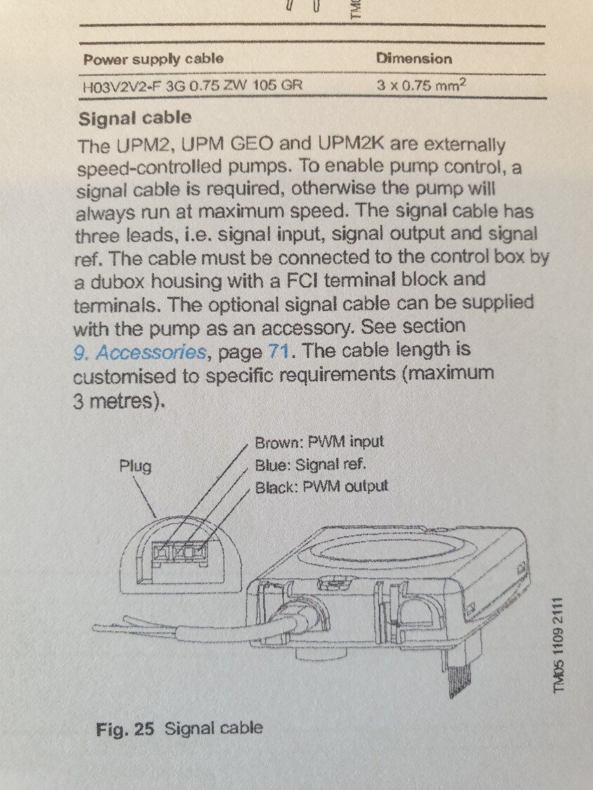
I have a PWM connector on my pump I just don’t know if it is compatible if I wired it up.