hi stuart
ive seen your new prototype controller with display
my question is
i have a sma sunny island it can comunicate via canbus with bms.
does it mean the new controller you building can comunicate with my inverter?
or are there different can bus protocols?
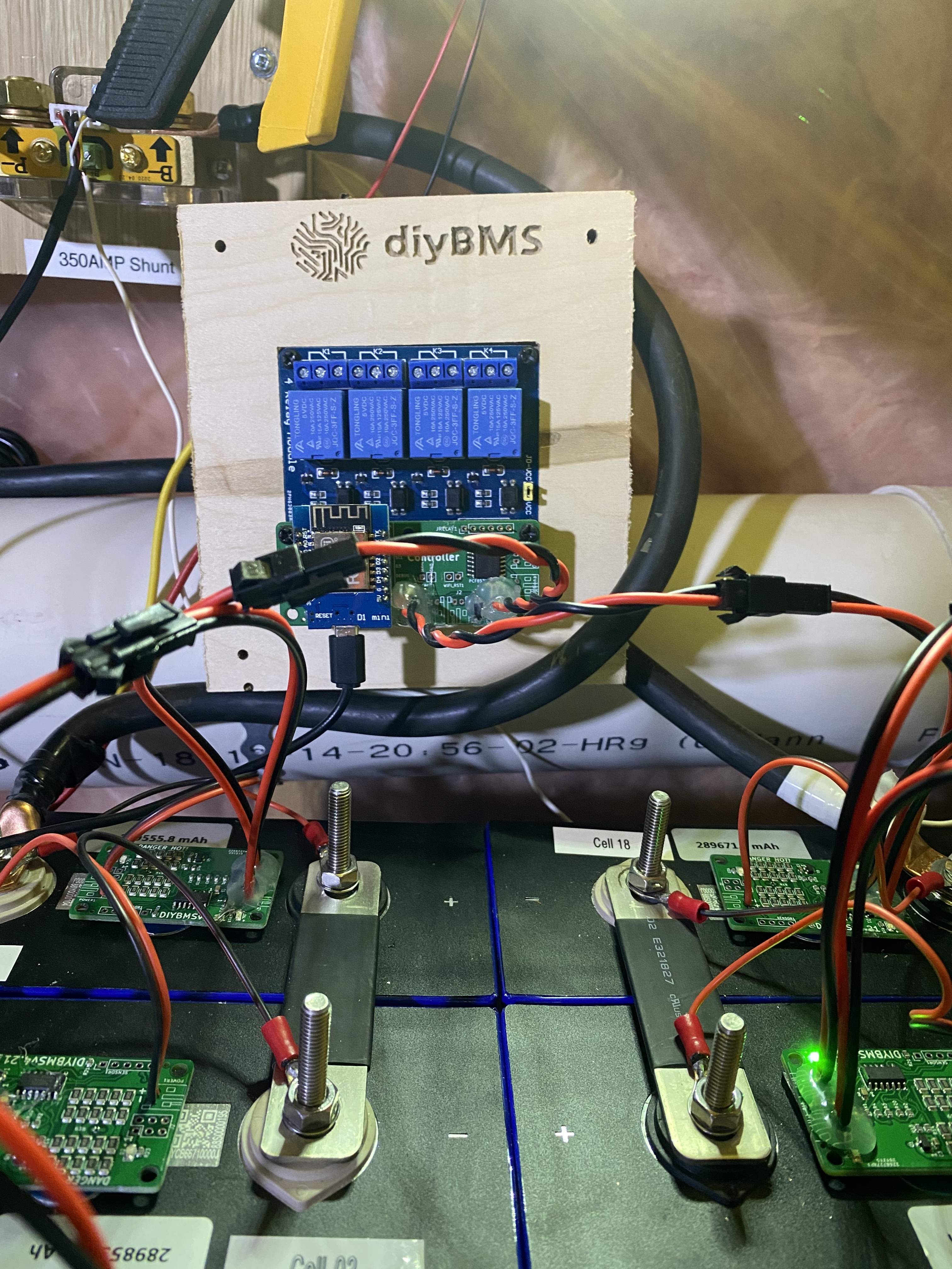
Well its been about 2-3 weeks now using the BMS and glad to report not many issues. I installed the modules to the sides of my 280ah LiFePO4 batteries and really the only issue I had was packet loss. Twisting the data wires from the 1st and last modules to the controller took care of the issue.
I did have programming and communication problems along the way all of which were a result of dry solder joints on the ATTINY or a header pin.
All in all very satisfied with the results. Would like to thank Stuart again for putting in the work to make this possible for all of us without the knowledge to do so on our own.
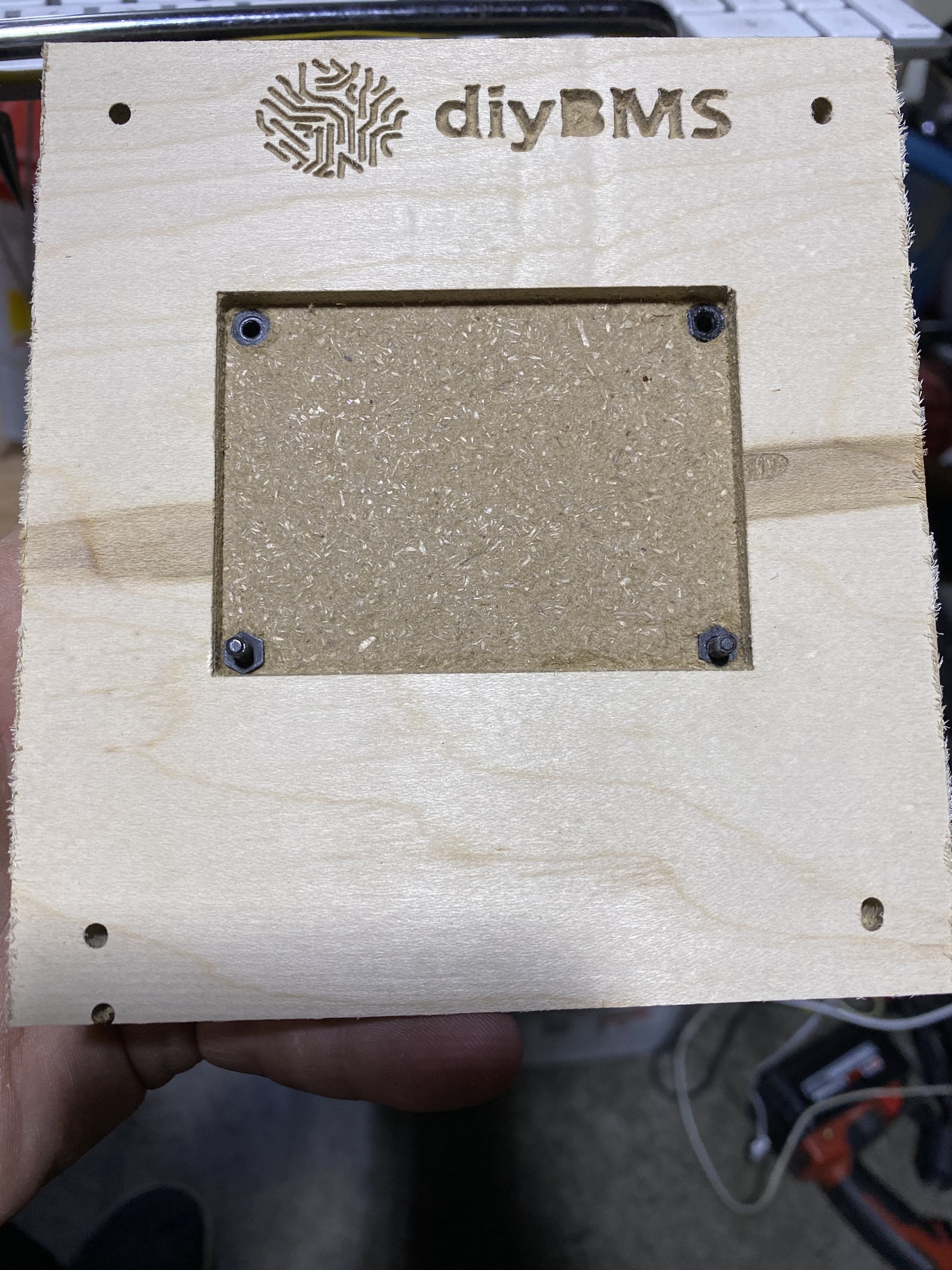
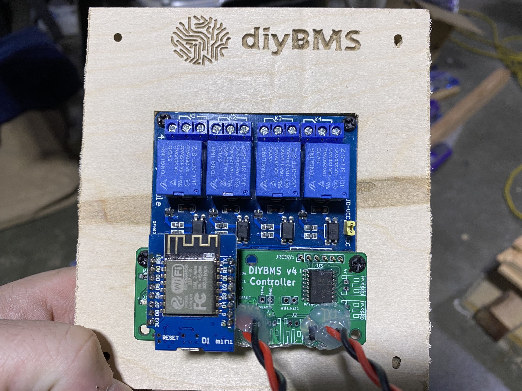
Here is my solution right off the wasteboard. I pushed a couple of nylon stand offs in the mounting holes I machined. I pocketed out a hole to perfectly fit the relay board.
Then I attached the relay board to the Veneered MDF I machined. Now the fact that the relay board pins and mounting holes PERFECTLY align with the controller can’t be a coincidence, can it?
Anyways, perfect fit.
I would like to build some of these leaf boards can you share the files? I am running 28k of leaf cells 14s8p. Has anyone built for more than 4 parallels?
@stuart When you mentioned that you made a custom module for both Leaf Cells, and the LTO cells, I got the impression that you would be open to making one for the 90mm holes spacing for the LiFePO4 Prismatic cells. Did I assume incorrectly?
I would gladly remake all my modules since I think that it would make for a much better install with minimized external wiring and less voltage drop.
Maybe even beefing up the balance resistors a bit for the larger cells. I have 280aH cells and the 850mA resistors don’t quite keep up if the sun is strong making lots of power.
Love to hear your thoughts.
PS, Do any of the pcb assembly shops have the attiny chips as part of their stock that you are aware of?
Hi, as @atanisoft mentioned, I didn’t make the Leaf one - although its the same circuit, just in a different “dual” format. I’d be happy to consider other styles/sizes, although I don’t really have the time at the moment as I’m desperately trying to get the next controller released so I can move on with the current shunt monitoring.
In regards to a 90mm hole spacing, I’d probably want to take a look at the various cell sizes available on the market, so I only need to create a single PCB for the majority of cells - perhaps with dual or even triple hole spacing to accommodate the various cell types. What cells do you have?