Hi - thanks for the files - will try to convert it and then I will come back to you.
Yesterday I’ve ordered pcb’s from your gerber files and received that email from jlcpcb:
Hi Sir or madam,
Well got your order with many thanks~
Sorry to bother you, but there is an issue that we want to confirm with you before proceeding.
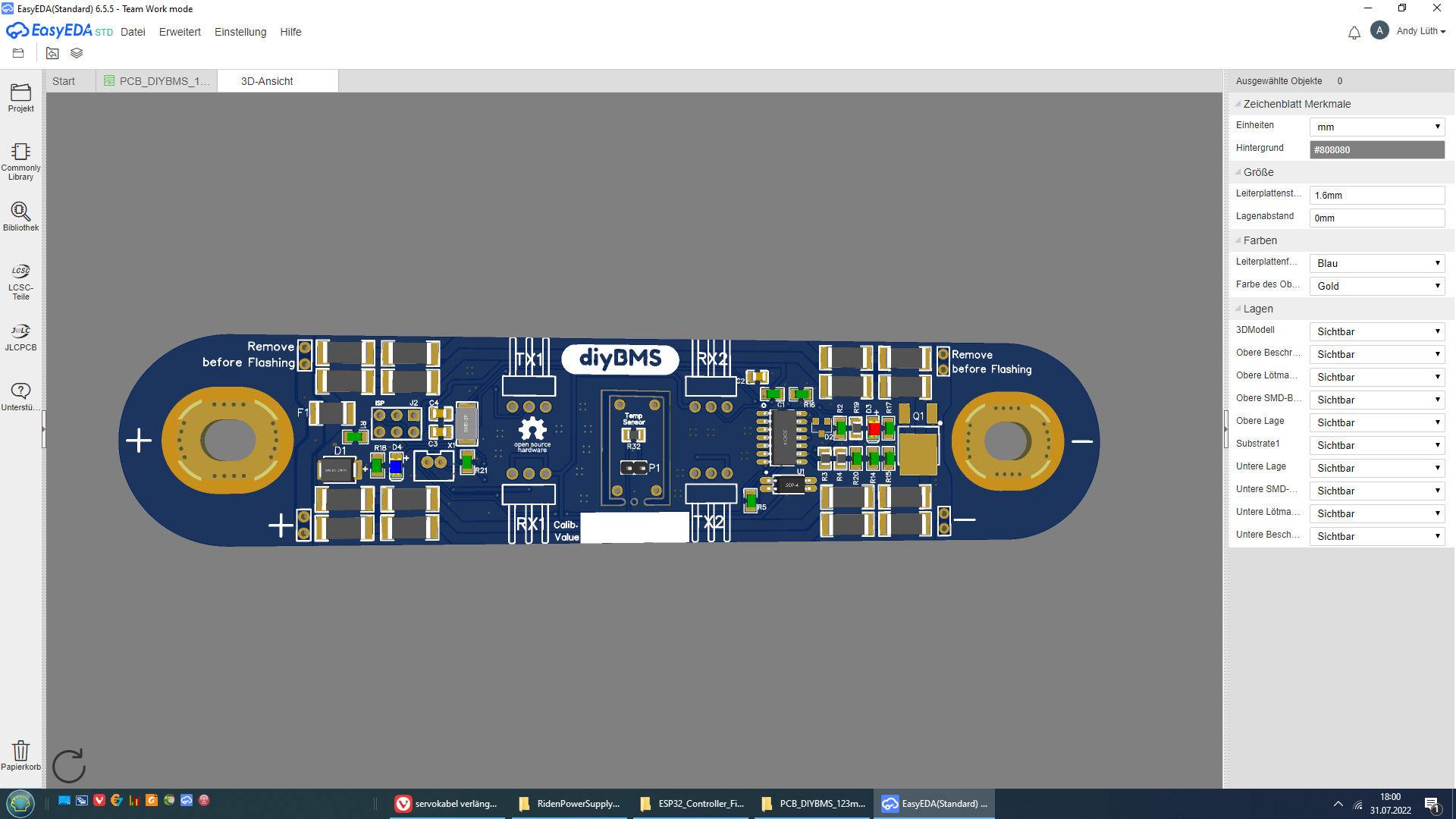
As shown below, the indicated hole on pad is non-plated hole.
Is that normal?
Shall we make it as plated through hole?
Your early reply will be highly appreciated!
Thank you so much!
Has this ever happened to you? I have also the same problem with visualization of smt as mentioned above but there was no questions about this from jlcpcb.
should be both plated it is so on the EasyEDA file!
Due to the various vias around it, and the fact that it’s going to be bolted on top of the bridges so will be clamped between 2 nuts wont make any difference, but yes tell them you want it plated. When I have some time I’ll check the gerber files.
Thanks again to Stuart, VAS, JAU and all others for the great work.
I finally found the time to go through the hassle of ordering at jlcpcb.
I could not work out how to use the “coupon” that stuart mentions on his github.
Intention was that he gets some reward for his work.
Will have to spend him a beer now ( or two )
I also got a complaint from the JLCPCB review team about the “non-plated hole”.
I checked the gerbers and indeed the file “Drill_NPTH_Through.DRL” has one hole declared which should be declared in “Drill_PTH_Through.DRL”.
As i do not have access to the edaeasy source i made a “quickandirty” fix.
Just moved the hole to the PTH drill file and deleted the NPTH drill file ( as it does no longer declare anything ).
I checked it online at https://tracespace.io/view/ and it seems to be okay.
I also made a bad mistake while trying to find a substitute for AQY212GSZ.
I thought it would be a good idea to use the “global sourcing parts” feature of their website.
Long story short i now have 23 parts arriving at jlcpcb in the future which i can not use. Because the controller modules are in production already and the y claim that this process is “unstoppable and uncorrectable” regarding the parts selection.
I should have known better after trying to order for some hours.
Their website is a PITA!
Sorry for shouting here…
Maybe it keeps others from making that mistake.
Now I took my time to change all PCBs.
Unfortunately one has an issue with instable voltage setting.
I try to find out whats going wrong. Attiny is not the problem.
All resistors seem to be OK. But I have to set around 4.5 to get the right voltage.
And during change of voltage its to high when higher and to low when lower.
Maybe one has an idea which component is kidding.
As much as i love the project, (kudos) i have to choose for an commercial BMS. Its impossible (or very complicated and expensive) to source all the components. I will look back on it in a years time (when i expand my battery) and hope this chip problem ends.
At JLC in the moment all parts are available.
Except one RGB LED.
It works without.
And for the cell boards you only need the Attiny. Available at Alibaba or Express…
Or some by me…
My solution is to not disconnect from the cell; instead I simply disconnect the programmer’s 3V wire.
Warning: this only works if the programmer is not otherwise grounded. In my case it’s a Raspberry Pi with a battery power supply from LiFePo4wered.com.
I saw the lifepo4 design and fell in love immediately, especially since I’m just changing from 18650 cells to 280AH lifepo4.
I like your lifepo4 design but there are a few things that have always annoyed me about the modules. It’s the small JST sockets, they’re just not for my sausage fingers And the arrangement of the resistors bothers me a bit.
I would like to have the resistors in a large group in order to use a larger heat sink and possibly cool it with a fan and of course a connector for the power supply.
The motherboard can easily be 60 or 65mm wide so that a 60x60mm heatsink and a 50x50 fan fits on it. The cells are 70mm wide.
I read in the data sheets that most 5V fans work in the voltage range from 3.5 to 5.5v. A simple fan control that allows the fan to only run from 40 degrees would be really great.
Since twisted pair and shielded cables are recommended for RX/TX, I would like to use RJ45 sockets and cables. Short Cat5 cables can be bought for little money and the design of the circuit board can certainly be adapted. Without the hole in the middle there would be enough space for 2 standing network sockets. The circuit board for the sensor will certainly find a different position if it were smaller.
I expect better handling and error-free data transmission.
When I think that I need 96 modules and should therefore use 192 of these little JST things, I get scared
Unfortunately, I lack the skills to adapt all of this to my needs. If someone bothers to change this I would in return make a donation to Stuart’s project or whatever is requested.
I was able to make a few changes. It wasn’t easy for me
I would be very grateful if someone would look at the result, I’m not sure if everything is error-free.