I can’t help you there. @vas should be able to help you.
Even though - thanks for your help.
if I knew how to do it, I’d have done it for sure! ![]()
Mind I picked Jau’s design and just shifted things about. OK, I spent an awful lot of time as the thing I know best is design houses, but got there in the end. It was in EasyEDA and I worked on that.
I’m not s/w or h/w engineer, tried on another project to create forks and failed miserably.
If someone explains (in fairly plain EN) how to do it, I can for sure do it.
If in the meantime @Maciej_Krasuski wants the files I worked happy to post them. Seems that the only useful thing I can get out of EasyEDA is a .json file. Is that what would be imported in something else?
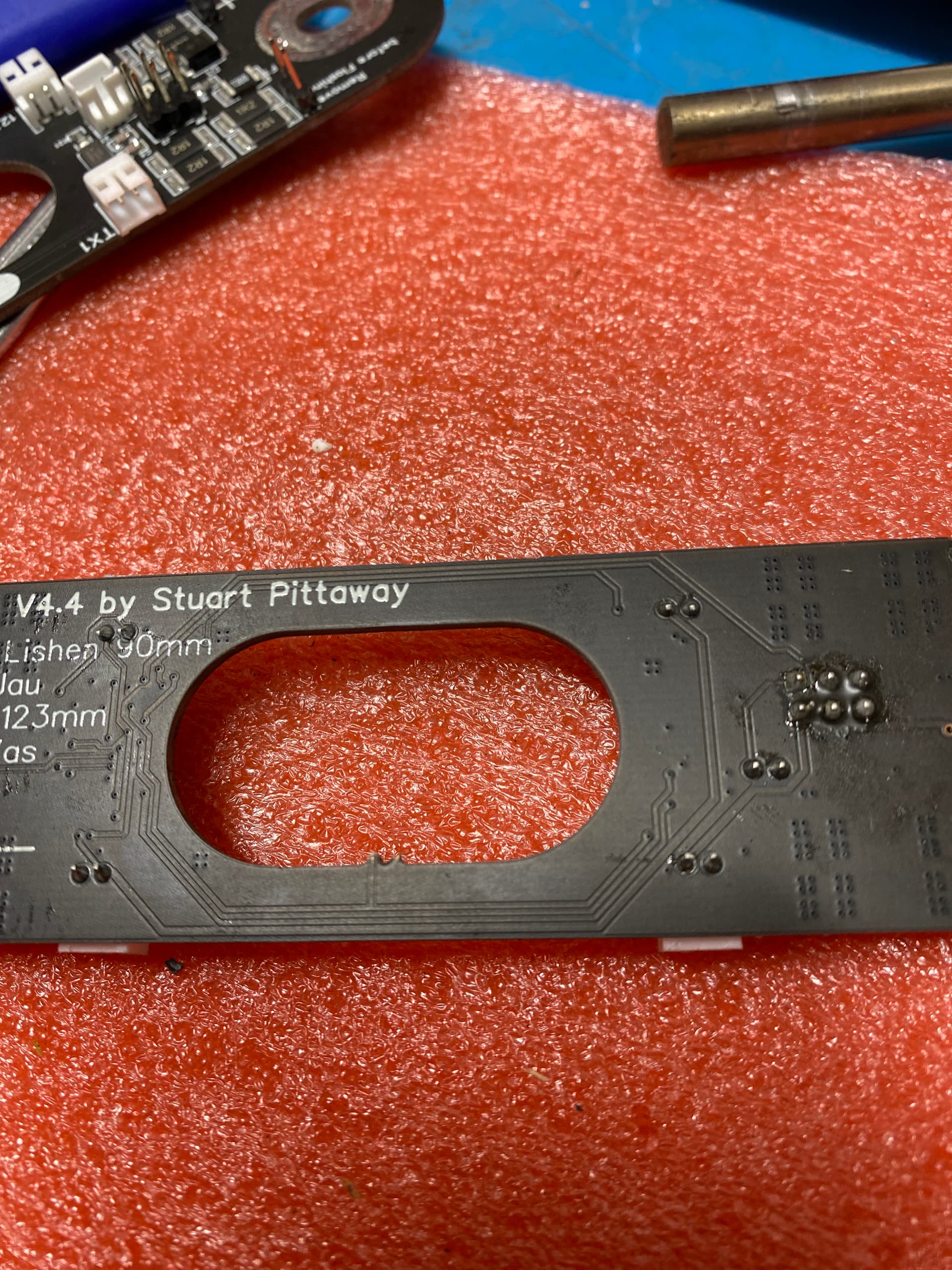
ah, and for the record I also have the latest EVE 304Ah and the post spacing is 123mm, so mine fit nicely. I understand that there were some 90mm post spacing in previous versions of EVE cells. Easy to measure it.
Hey, everything arrived now.
In my test setup with just 2 cells, I have the „problem“ that the leds are not flashing and when I break off the temp sensor, connect them, I got no Temp information.
Do you have an idea?
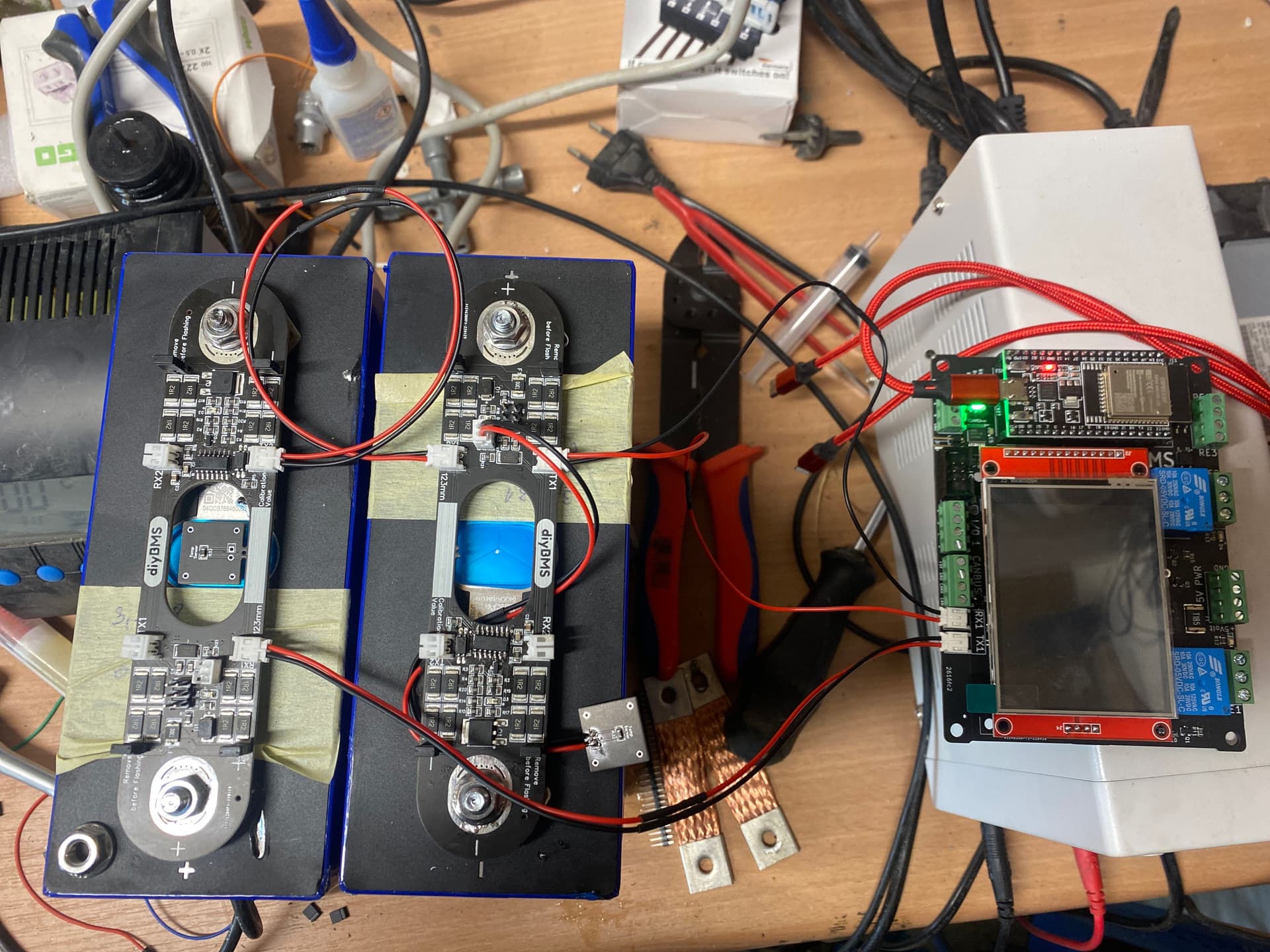
attiny’s soldered properly, cannot see where pin1 is but it’s towards RX2 connector.
code uploaded OK?
I see you have placed jumpers on all 4 points (2 on + and 2 on -) if you do have V in the board it should be fine and running/flashing even without the controller.
please update with more info. Has the controller been used successfully before with other cells, guess so.
no flashing at all means there’s no power on the board. Only realistic way of achieving that is by not jumpering at least one of the jumpers on each side!
V,
Thanks for your kind reply.
Yeah I tested it as you Mentioned.
Attinity is correct mounted.
Also flashed but I have the problem on all boards. Via the the esp32 board.
Maybe there is a problem on all attiny?

This is the one I ordered and got.
There was also no Problem at flashing
definitely puzzled!
few Qs, please reply one by one to avoid confusion!
A. have you got any other modules (non mine 1.9F!) and are they working with your ESP controller? IOW, are you sure the issue is with the 1.9F modules and not the controller?
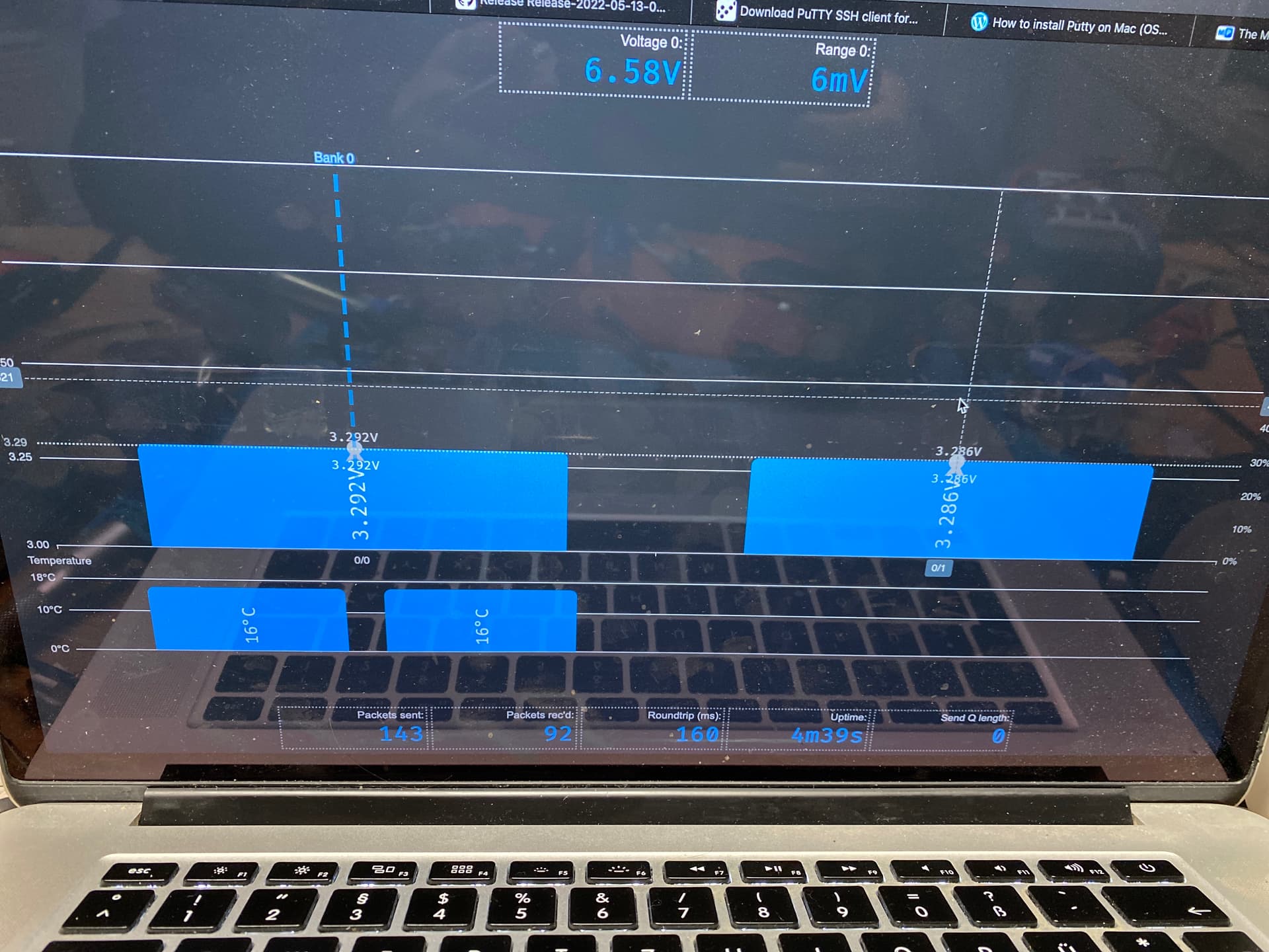
B. what’s the difference between 0/0 and 0/1 above? I mean in h/w and connections the one has both temp sensors working, the other none!
C. which code did you up? V440 which one normal/5K/9.6K?
D. did it report that upload was OK?
cheers
V.
A. Hey,
Bi I just have your 1.9F Modules.
Nope, not shure. But one module is working, but without lights.
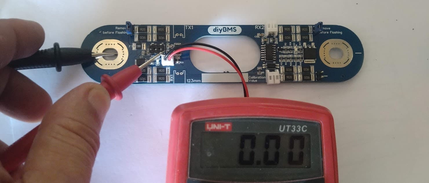
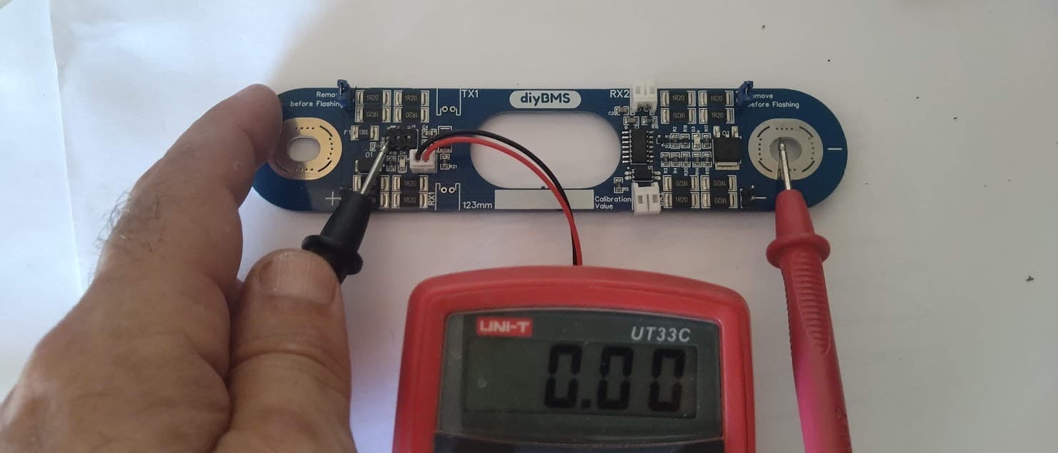
B. Yeah, as shown in the pictures before, I broke of one sensor and connected him via jsp cable.
Hardware is Same.
C. V440 9k6
D. Yes shure
LEDs soldered in the right way?
Hope so, Chinese guys where doing it, they are really small ![]()
But nebermind the lees, actually I don’t care about them, but what is wrong with my temp sensor
Hi, is the blue LED working during flashing?
Should flash a little bit dimmed.
If not I expect they soldered the LEDs in wrong direction…
I had on one original 4.4 board the same behavior with the temp sensor.
Was fixed after I resolderd the Attiny with hot air.
Hey Joshy,
Will reflash some Module and check. But indon. think, that they where flashing.
Mysteriously they are working fine, if the temp sensor is not broken out. Or do I need to connect the small „wires“ on the backside?
very odd, I’d try resoldering/reflowing the ATTiny chip and checking again the external temp sensor soldering.
The one that doesn’t have the ext temp broken off shows both internal and external temp. Which is alright as I have two thin lines leaving the PCB going to where the JST connector is. Make sure that when you break off the temp sensor the two lines are not shorted (would be very difficult to do, but you never know!)
Also what happens when you unplug the JST cable of the ext sensor on this module? Is the internal temp by any chance back on?
Also if you plug this ext sensor to the other one (without breaking off it’s own!) what happens?
In order to avoid all the diodes going the wrong way round, I’ve added + on the silkscreens on all diodes/leds.
Anyway, I’d bet it’s dodgy soldering somewhere.
Do a few more and see if you get one running properly to have a control point for the rest!
V.
Hi Vas, sorry for late response but I missed email notification. I don’t know EasyEDA, I’m rather kicad user so it will be difficult for me to explain this to you ![]() I found converter from EasyEDA to kicad. It’s called easyeda2kicad. So if you could download it convert and send me those kicad files, then I’will check if this is ok and I will try to explain you how to put it in your github acount.
I found converter from EasyEDA to kicad. It’s called easyeda2kicad. So if you could download it convert and send me those kicad files, then I’will check if this is ok and I will try to explain you how to put it in your github acount.
Nevertheless if you said that it should fit 304Ah I’m gonna order it. The latest version of your board is 1.9F?
Hi,
Amazing design!
I want hem for my cells. they are 97mm m6 spacing. Can you share your EasyEDA so i can rework it ffor my need.
Let me know.
as I said earlier, EVE 304Ah cells changed from 90mm post spacing to 123mm spacing sometime last year. Make sure you get the latest ones and not any leftovers ![]()
this is the 123mm 1.9F .json from EasyEDA. Indeed you can use this EasyEDA 2 kiCAD tool to convert it. Let me know how it goes.
PCB_DIYBMS_123mm_v1.9F_2022-06-01.json.zip (132.3 KB)
@Stijn should be easy to reduce that post spacing, not sure about going down to 97mm though ![]() will be a bit tight!
will be a bit tight!
cheers
V.