Any of those work for me. I suggest you start with just the V440.
Vas has already stated that he tested these at 100% PWM and with his latest resistor layout no heatsinks were required. I can’t think why you’d need so much cooling? The balance resistors are only used at the top
of the charging cycle. Even if the cells are poorly matched the balance current required should be related to your charging rate, ie you drop the charging current as the cells are top balancing. I’ve seen my cells at well over 30 degrees ambient and still no need for additional cooling. After the cells have been balanced once you shouldn’t get a large drift between cell SOC so you only need large balance currents when the cells are new and you can get around that by charging more slowly for longer at high SOC then change your BMS and MPPT settings when the cells have completed a balance cycle a couple of times. With LifePO4
there is only a very small change in SOC where you would be balancing so charging with more current is fairly pointless, ie you’ll find at the top of the charge curve there is a rapid change in voltage for little change in SOC, that’s where you’ll be balancing the cells.
Also in his design you can see the cell vent which may be quite useful.
One of the original design goals of these modules was to reduce the twisted cable lengths so communication shouldn’t be an issue even in large packs. Perhaps you could use a tool for the JST connectors? I agree they are a fiddle.
… and you can purchase JST cables in custom lengths quite cheaply on Aliexpress.
Thanks for your detailed answer.
I think where heat is generated, it should be dissipated well. In any case, I will mount 4 small heat sinks. Let’s just call the reason “German Angst” ![]()
I’m a craftsman, my motto is “having is better than needing” ![]()
As for those lousy little JSTs…I HATE THEM. I find the JST as useful as a fly in a meal.
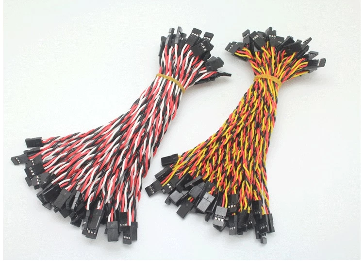
I definitely want to use the Futaba RC servo cables. I’ll see if I can change the design so I can see the lid.
The Futaba cables are available on aliexpress for little money
1 Like
/
Um es mal auf klar Deutsch zu sagen: total verrückt.
Das Futaba Zeugs nimmt mehr Platz auf der Platine weg. Die Kabel sind nebenbei zu lang.
Die JST Kabel tun was sie sollen.
Ich habe mir auch erstmal Kühlkörper gekauft.
Die liegen immer noch Inder Tüte weil ich nie mehr als 40 Grad beim balancen sehe.
Die VAS Boards haben schon mehr Widerstände als das normale 4.40 Board.
Die Wärmeabfuhr ist daher deutlich besser. Auch vom Design her.
Was Lüfter angeht: hatte ich auch drüber nachgedacht.
Wenn man das Design versteht: da abgreifen wo die Widerstände angesteuert werden.
Schon läuft auch ein Lüfter wenn sie Widerstände warm werden
Aber all das braucht man nicht.
Auch ich bin Handwerker. Aber andere Philosophie. Je einfacher desdo besser.
Aber der gute Deutsche braucht für alles ne Versicherung.
Eine Stoppmutter mit Sicherungslack, Splint durch, Sealer drauf und verschweißen.
/
1 Like
Ich habe die Kabel in 5,10 und 15cm länge liegen und kann sie auch selbst krimpen. Die Schirmung ist gut und sie sind fertig verdrillt. Platz ist auf der Platine genug für die 1x3p 2.54mm Header. Mit ein bisschen Geschiebe geht das.
Glaube mir wenn ich sage das meine riesigen Pranken nicht für JST geeignet sind ![]()
In meinen Händen wirkt ein Fussball wie ein Tennisball.
Ich ging von der Wärmeentwicklung der 4.21 Module aus die ich in Benutzung habe. 60grad sehe ich da oft.
Es ist gut zu wissen das es mit den LFP Modulen nicht so ist. Somit “brauche” ich für mich nur die 1x3p Header damit ich glücklich bin.
Du schiebst die Kabel doch nur einmal drauf.
Dann fasst Du da nie wieder an…
Ich mag die trotzdem nicht ![]()
I tried to use the files in this zip but the preview was very strange (although that is not unusual with them!) BUT I was not able to add it to the cart as I got an error
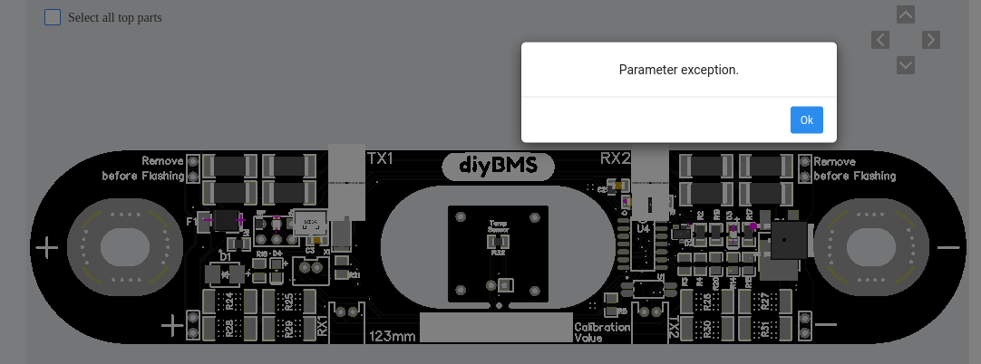
Any ideas??
Are you trying to order it with jlcpcb?
i ordered it there in June and it went through without errors.
regards
Joerg
Thanks for replying - I tried everything and eventually worked out that there is a limit to the number of PCBs you can order with the ‘economic assembly’ service
We can’t use standard assembly as the PCB is too small
Of course, you would expect the error when you select the number of PCBs for assembly rather than when you try to add it to the cart!!
For to setup 2 Batteries for a friend I need 30 more 1.9f boards.
I had to change the RED LED and the 1.2 Ohm Resistor to a diffrend manufacturer.
The ones from the cpl were out of stock.
I tried to order them and got a xceld order.
Because the cutout snaps would be to less and must have a minimum of 4mm.
Today I ordered again. Totally the same. Now its in production.
It seems it depending on who reviews the order…
I had an email exchange with them - they are concerned about claims if the middle falls off.
I wrote stating that I would not claim for any that might fall off (none did)
P.S. sorry for taking all the resistors!! I emptied their stock!
Thats no problem. I took a resistor with the same specs from a diffrend manufacturer.
Same with the red LED.
But today I got an email that the copper pads around the wholes are too small.
Indeed the pads would be smaller than the whole…
Strange. Its the same file I gave them for production…
I sent them a picture from already produced pcbs.
Hopefully thats enough to make it clear…
which size is good for lifepo4 3.2V 320ah?
as it is all about 280ah in this thread, is it good for 320ah as well?
how far apart are your terminals? that is what decides the board, rather than the Ahr rating
1 Like
iirc it’s good for circa 121-124mm spacing of the posts and expects up to M6 bolts/studs/whatever you call them.
I’ve not ordered any cells lately, but it seemed to be either narrow (90 or so mm) or wide which was the reason I did it.
Edit: mine are 304Ah, unless absolutely sure I’d wait to have the cells in my hands before ordering!
cheers
V.
Thank you, and the electronic is same for each type of cells and can handle 100-320ah cells? nothing needs to be adjusted? I ordered 96 cells 3.2v 320ah and plan to make 15s6p to have 48V, is is a good plan? I saw that some folks connect 16 and not 15 but that’s not 48v anymore, so not sure what is better.
I can only answer on the first bit, yes, pcb design is fine for practically any Ah, after all passive balancing is at around 1A, bit more with these, so nothing really changes as you go up in cell capacity.
That’s a big battery, what are you going to run out of this lot if you don’t mind me asking?
V.
I plan to connect them to 3 hybrid inverters that will be AC coupled to existing 10KW on-grid installation with 3-phase 16K SolarEdge Inverter (plan to add some PV to go up from 10 to 16KW). My daily consumption is in average 20KW, with min consumption during day at about 600W, I plan to connect the whole house on all 3-phases and be able to survive a couple of days in case of power failure with normal power consumption, also fully benefit with energy generated by PV when being cut from power distributor grid - my current installation is capable to produce 68,1KW in single sunny day (top result) I also have electric car (plug-in).
That was not an initial plan to go for such a big battery but I found very cheap ones on aliexpress and decided to make a try. I hope they will come and will be in good shape ![]()
1 Like