Issues with TL432 (voltage drift)

Building a lot of battery. 3kWh Building Blocks. Up to now … puh a lot.

more than 30 I think. From Offgrid to Solar energy storage.

But nothing commercial.

Plus the Modules that were wrong ordered, wrong built, wrong redrawn for panelizing, wrong D1, defect Attiny …

1 Like

Wrong voltage reference installed.

Hi, is there a way to correct a wrong voltage reference “D1” with parameters on the webgui or in code?

Stuart changed the Voltage reference to a 1,24V one.
In the actual BOM File is the TL432CSF_C126100.

On one of the last JLCPCB orders before this came up, I made a try with a TL432_C171428.

Now voltage shown with a lab bench power supply is not stable over time. (see attached pic, up to 40mV +/- on constant 3,400V)
In the datasheet there is the difference in mV/V 2.4 to 2.7.

Is this D1 chip total useless or is there a way to adopt the settings in Webgui or in code?

Ok, that part should be good, its 0.5% rated - are there any markings on the chip?

JLCPCB description says “VOLTAGE REFERENCES 1.24V 15V ±0.5% SOT-23(SOT-23-3) ROHS”

However the datasheet [https://datasheet.lcsc.com/szlcsc/SK-TL432_C171428.pdf] doesn’t mention a 0.5% version, only 1% and 1.5%

At 1%, the spec sheets says voltage of 1.2276~1.2524 at 1.5% 1.2214~1.2586V

So doing the math…

Input voltage goes through a 68k/27k resistor divider, 3400mV scales to = 966.31mV, you should be able to read this with a multimeter/scope on pin 5 of the ATTINY (or between R3/R4).

This 966.31mV is then compared against the 1240mV reference using the ADC in the ATTINY chip.

Reference voltage of 1240mV over a 10bit ADC gives each step, 1.2109375mV, so the ADC would read 798 (maximum is 1024).

This 798 is then internally scaled back up to a readable voltage using the calibration number in the web interface. So 798 is multiplied by 2, then by the calibration value, 2.130 = 3.399V

I would always expect some bit flipping to occur with the ADC as it’s never perfect, a single bit will have a resolution of 1.2109375mV *2 *2.13 = 0.00515V

So in the example of 3.400V input voltage, the BMS should read 3.394V to 3.405V - at best/perfect world. So I’d expect about 0.6% error.

If we look at line 3, you have 3.383 and 3.405 ranges, which are 0.5% and 0.14% error rates.

Line 1 is 3.382 and 3.413, which are 0.5% and 0.3% error rates.

The main problem you are going to have is if the voltage reference is drifting.

So the questions:

  1. What range are your calibration numbers in? Should be around 2.1XX or 2.2XX.
  2. I’ve read reports that the TL432 chips are more accurate when driving more current/load, we could look to add a small resistor to the board to achieve this
  3. Do you have anyway to measure the voltage reference accuracy?
  4. It may be the speed at which the voltage reference switches on and provides a stable reference, without a scope I don’t know what this looks like - although we could introduce a delay in the code to allow this to become stable before taking a reading.

Thanks for your excelent explaination!

BMS should read 3.394V to 3.405V - that’s what I experienced with working modules.
Unfortunattely I see 3,378 to 3,413V and for LiFePo this is a huge range.

Answers to the question:

  1. Calibration numbers are most in 2.19x to 2.2xx range.
  2. is possible to test.
  3. 1,2532V measured with the Multimeter. With the osciloscope it looks a little bit different (see Answer 4)
  4. The Vref seems oscilating with about 5,5MHz between 1,15 and 1,28V

On my older boards (with the 1,25reff D1), this oscilating is not really visible.
So it seems that I have many defect D1.

Attached pic1:
Pink/violet pin13 ‘old’ Module with 1,25V D1
Yellow(green) pin13 ‘new’ Module (oscilating)
Blue Pin 5 ‘new’ Module

Attached pic2:
Yellow(Green) - oscilation D1-Signal from ‘new’ 1,24V D1.

Attached pic3:
Violet - D1-Signal from ‘old’ 1,25V D1.

Attached pic4:
“empty” new Module without attiny soldered. Only power to 1,24Vreff D1.

Great you have a scope, I’m just about to buy one :slight_smile:

It does indeed look like faulty/low quality TL chips. From the data sheets I think it needs to draw at least 1mA to be in stable regulation. I’m running the chip in “Fixed Zener Mode”
[TL431 - Wikipedia] which just connects the pins together to force the output to the reference voltage - either 1.24V or 1.25V.

It looks like it takes about 3000ns for the “old” (pic3) voltage to stabilize, which is quicker than I expected.

On the TL chips you have, the output simply goes into the REF pin on the ATTINY. Could you add a 600ohm resistor (or similar value) between the output and ground and see if that pulls the TL into regulation? 600ohm would put about 2mA load on the TL chip, which should be more than enough.

Hi.

Yes, a scope is very useful.
We used it a lot when making a ACS758 Current sensor get to work with the existing V4 controller board. Current measurement is stable and for our needs correct enough.

The scope also shows now that the “old” D1 (1,25 Vreff) stabilized in about 4us, but correct voltage comes after about 0,3ms (yellow line).

And for the resistor question, on the TL432 (1,24Vreff) Boards a resistor helps:
Resistor parallel to RL: 2k not stable, 1k stable
Resistor parallel to D1 (between output and Ground) 1k not stable, 620 stable

Now, which option do you think is the best for this modules with the “wrong” D1:

  • changing the R2 resistor from 1k to 470
  • adding a 620 resistor in parallel to D1
  • or exchange D1 with a supported version

My new scope arrives today - I went for a Siglent sds1104x-e.

Looking at the datasheet for the TL432, it recommends a load of 1mA (min) for the TL432 to operate correctly. It looks like the quality of these parts vary a lot, I’ve got lucky by recommending the devices I have so far!

I would add a 620 resistor to D1, this should drive the TL432 to drive a current over 1mA whilst the voltage readings are taking place. It may be worth trying other values of resistor to get a stable result.

Don’t forget to measure the current/response over the typical lithium cell range of 2.5 to 4.2V.

I think this resistor should be added into the base design - or potentially use a different reference chip completely. Perhaps the Texas Instruments LT1004ID-1-2 ?

Got the new scope, liking it so far!

This is the output of the TL432 chips I originally recommended (no longer stocked) UTC(Unisonic Tech) TL432G-AE3-R which was part number C171461

It has a similar switch on time to the “old” D1 you mention above, it has stable output after 1600ns.

Adding a 680 ohm resistor over D1 and ground, gives this output, which gets rid of the peak

Below is the original V4.00 module, which used the LM4040BIM3-2.0 outputting 2.048V, which was useful for a 1024bit ADC like the ATTINY, unfortunately this is no longer any use, as cell voltages now need to read below 2V for certain battery types. This one is much slower at switching on to stabilize, which is why I needed to put a delay in the code to make it work correctly.

1 Like

Just to add, this is easy to do using a “normal” wire lead resistor, just put it on the sensor1 pins 2 (marked 2volt) and 5 (gnd).

The 2volt marking is a carry over from the old 2.048V reference I used.

Really nice scope!

It also can decode a couple of protocols.
But often it is easier to use a dedicated Adapter on the PC, after you figured out how it works.

@Placing:
My first thoughts were - just to solder a “regular” resistor over D1. Then I took a look to the schematic, and found that “Sensor1” has all necessary connections.
Fortunately you think the same way!
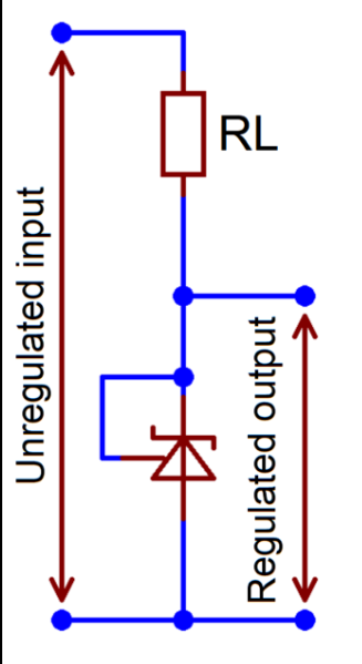
@alternatives:
You can also take a look at the LM4040 Series, you’ve already used. There is a LM4041 1.225V Version.
The LT1009 (and siblings) look good, but are quite expensive.
But with both of them I do not have any experience.
I find, the TL432 makes a good job for its price (beside of my oscillating version)

I’ve only used MCP1700 Series to get stable 4V (out from 5V) for the current Sensor.
But the Input Voltage has to be at least 2,3V.
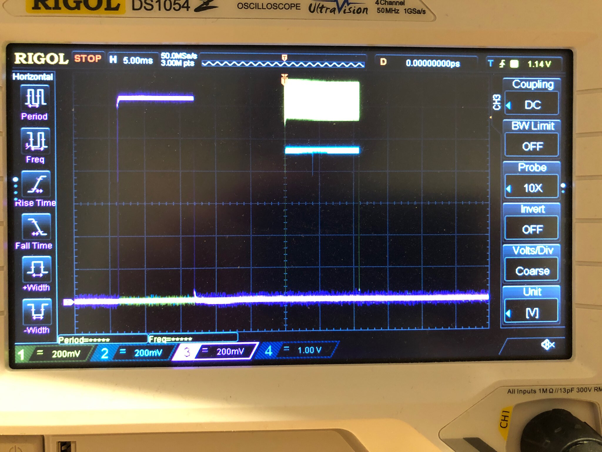
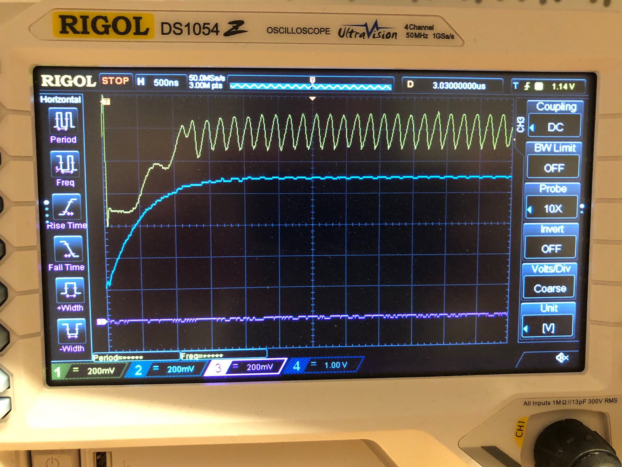
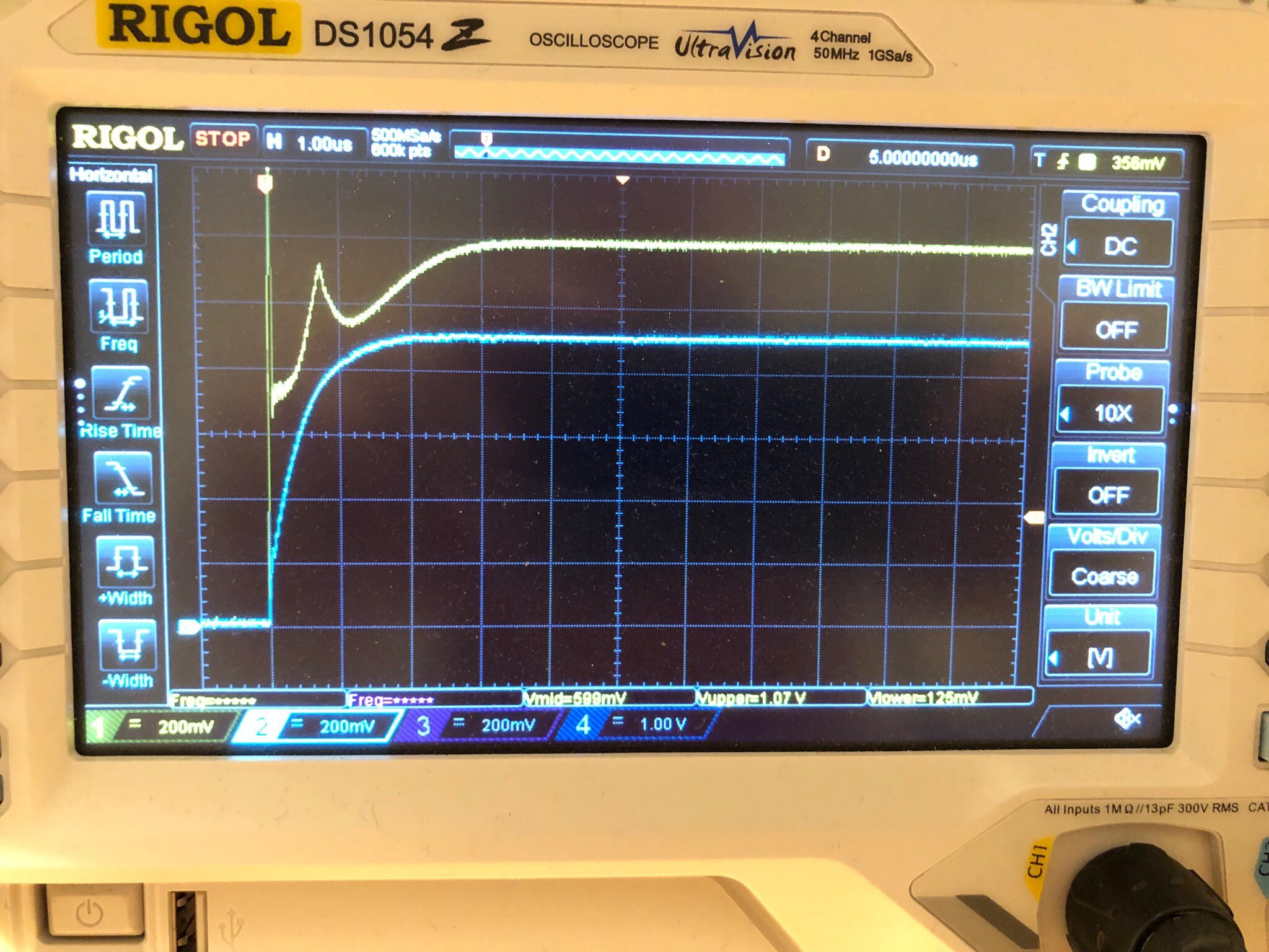
@unstable TL432
Because R2 is 1k, it is not possible to cover the complete Voltage range with 620R.
1k series 620R means, that when I have 1.25V on 620R, R2 “needs” ad least 2.02V.
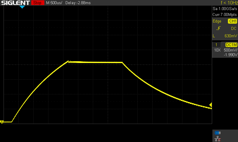
So Below 3.27V the Voltage on D1 starts to drop because of the voltage divider (R2 with additional 620R)

With 3,4V and 620R in parallel to D1 it is stable, but starts above about 3,8V to be unstable.

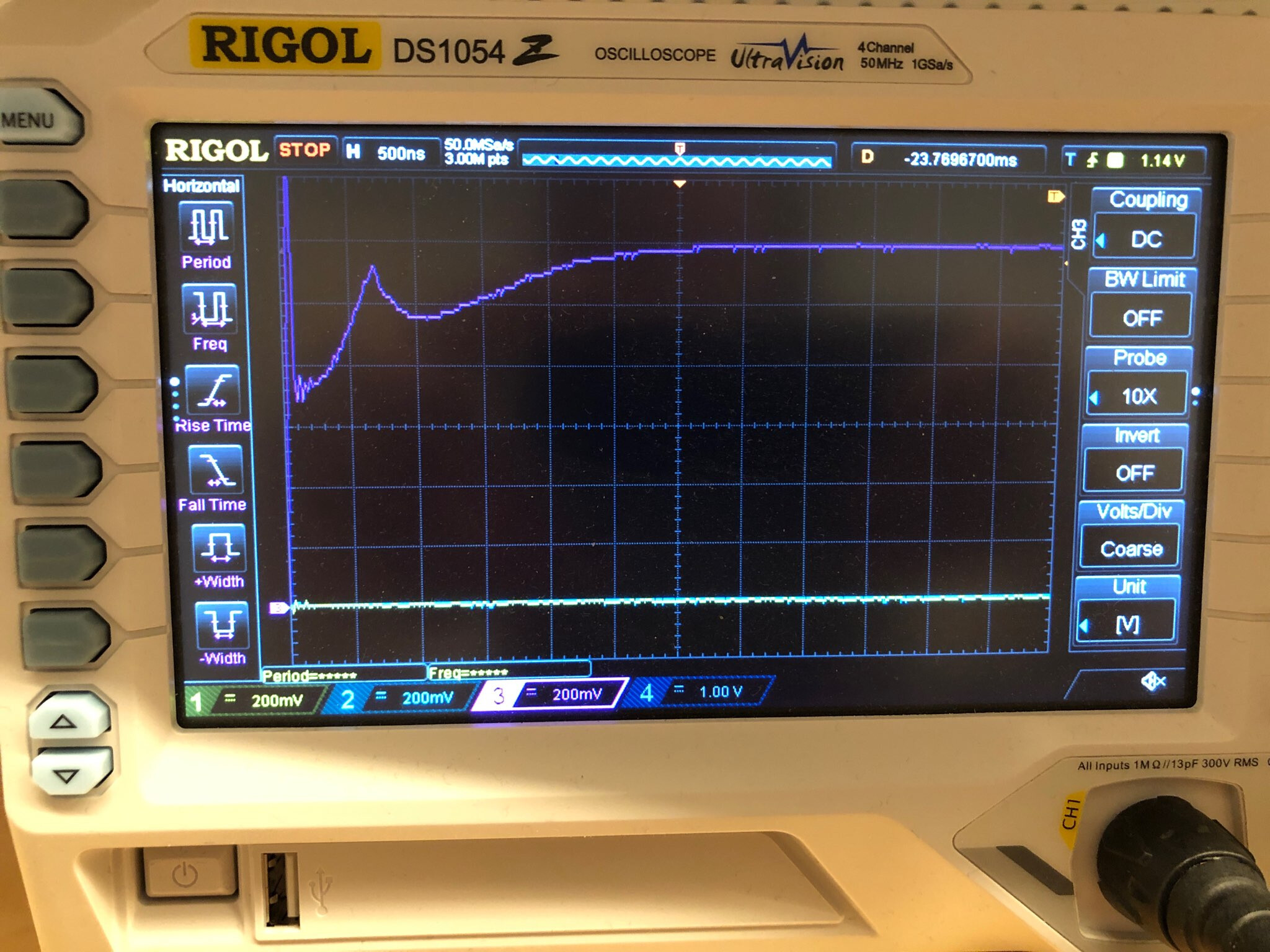
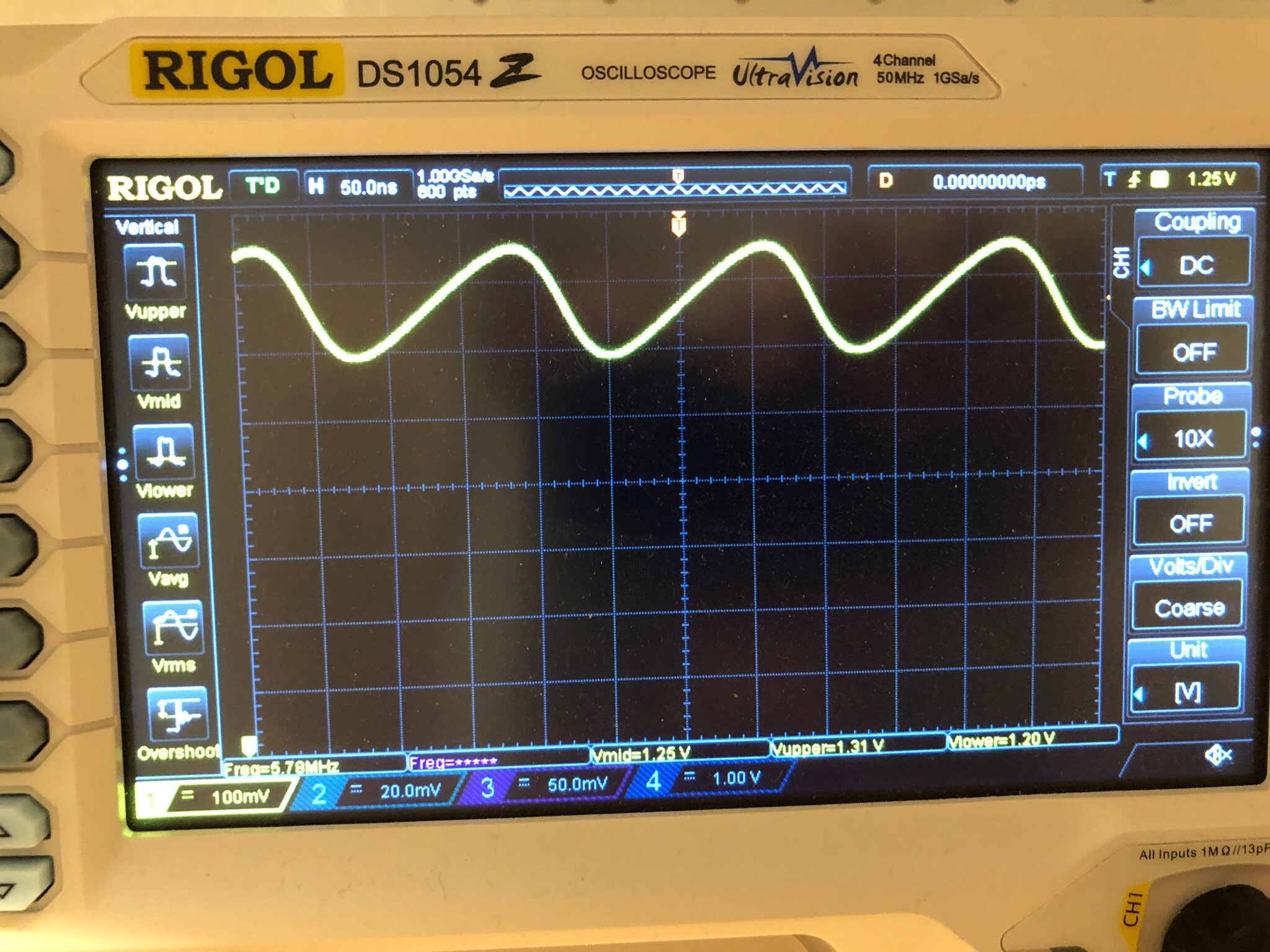
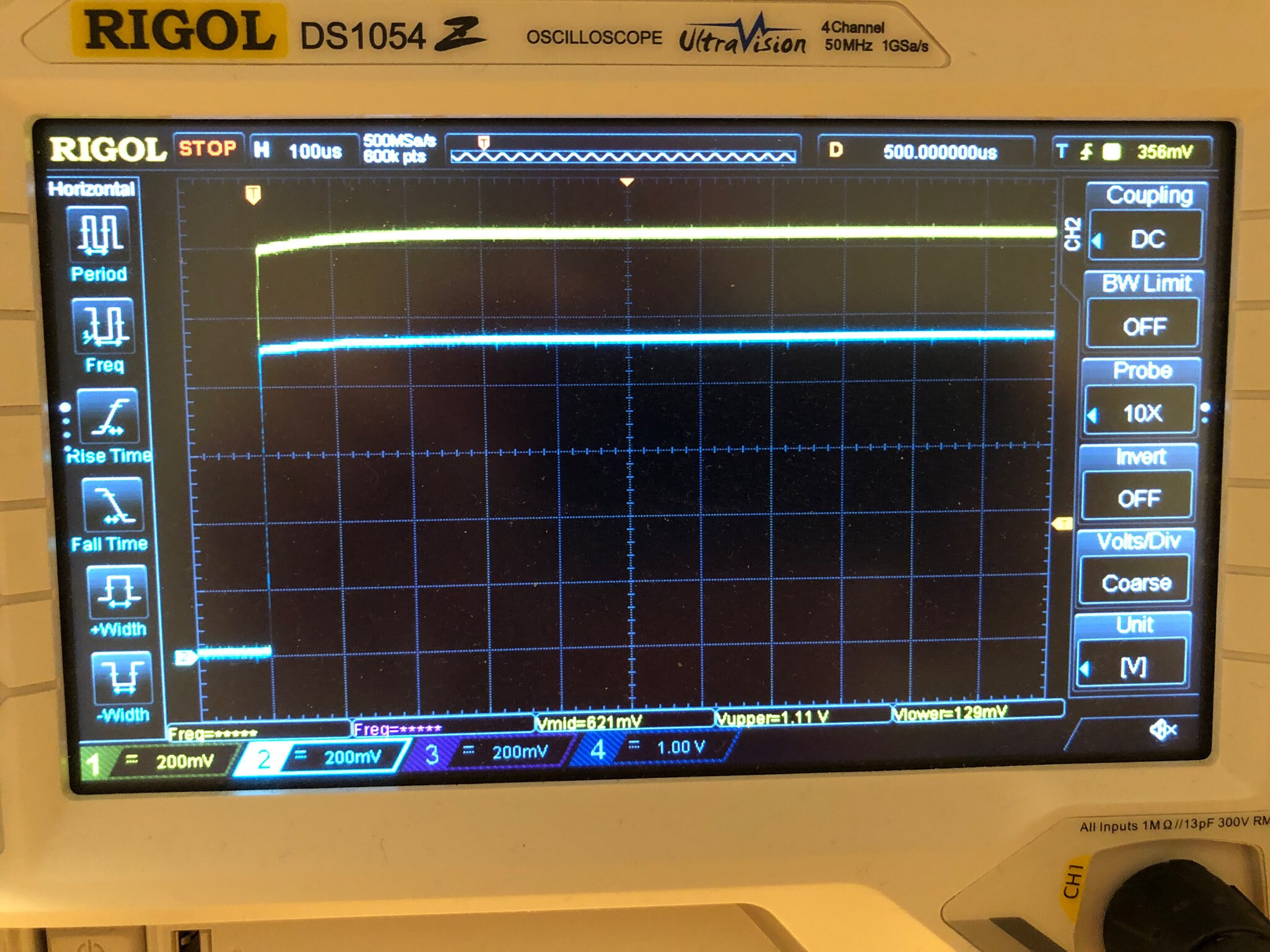
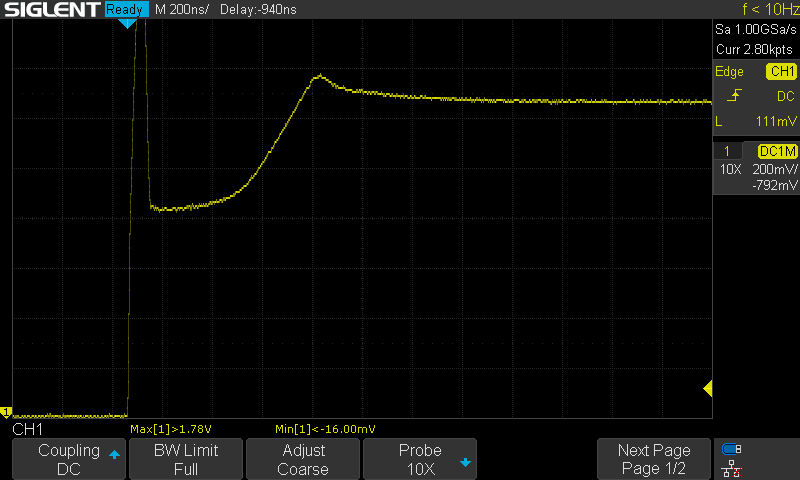
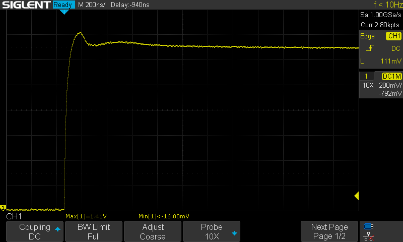
Because of this, I tried also to change R2. But after some not successful tests, I decided to add a capacitor to “shorten” the 5MHz.
Because of the high frequency a small capacitor is enough. I tried 100nF - that was enough to make it stable over the whole Voltage range.
Then I looked to the data sheet. - I found the section “Stability Boundary Conditions”.
When I correctly read the data sheet, in our configuration it should be less than about 5nF and greater than about 6uF to be in the stable area.
With 2n2 or 4n7 it is not stable, with 100n or 1u it is stable. Even when the data sheet says it is not.

So to be on the save side and within the specs, I think we have to use 6u8 or still 10u.
Or is 1uF enough, just because it works? - what do you think?
The strange thing is, that they also say that no Capacitor (=below 5nF) is also a valid and already working! Configuration to prevent oscillating.
So - the more I think about it, I think I had only bad luck and got an out of specs TL432

Your thoughts? - changing D1, adding capacitor? (1uF, 10uF?)

Changing D1 is probably the best way forward, although its a tiny part!

I’ve also started to look at the LT1004ID-1-2 reference, a lot more expensive ($0.47) compared to the TL432 (about $0.05 !) but specs read much better 1.235V ±0.32% 20PPM/°C

Hi,
we will now replace D1 on the “wrong ordered” PCB’s with working ones.
There was a mistyping in the Product numbers.

The “oscilating” were these ones:
UTC(Unisonic Tech) | UTC(Unisonic Tech) TL432CG-AE3-R | Voltage References - LCSC.COM

On the new order that arrived we used this voltage reference:
https://lcsc.com/product-detail/Voltage-References_Shikues-TL432_C171428.html
These are working fine.

Greetz

1 Like

Hi
I just placed an order and cancel it
we need to change D1 by Shikues TL432?
thanks

AZ432ANTR-E1
seem to be good alternative ref1.25v low deviation

Hi, if available always use the ones from Stuart‘s actual BOM/CPL files.

This topic here is only showing findings on using a wrong one.

C171854 doesn‘t work
C171428 works - but no official recommendation

hi
thanks
what do you think about C84139?

it seem to be a great value, but need to change code back to 1.25V

There are no code changes needed for 1.24V vs 1.25V

If you use the current BOM from the jlcpcbassembly branch, it swapped to this part a few weeks ago…

“TL432CSF”,“D1”,“SOT-23”,“C126100”

HTC Korea TAEJIN Tech TL432CSF
Manufacturer HTC Korea TAEJIN Tech
MFR.Part #TL432CSF
LCSC Part # C126100
Package: SOT-23-3
Description: VOLTAGE REFERENCES 1.24V 18V ±0.5% 50PPM/°C SOT-23(SOT-23-3) ROHS
Datasheet HTC-Korea-TAEJIN-Tech-TL432CSF_C126100.pdf

Probably fine, just check the pins are the same as the TL432.

Yes it is same pin and spec are better

I will try this , I will report you some measurement if you want ?

looks this datasheet, really better for only few more bucks: $0.0809

Looks good