DIYBMS for Lithium Iron Phosphate battery cells (LiFePo4) 280aH

Hey Stuart, Here is the idea for the 280ah cells we spoke of for the purpose built diyBMS modules.

I will post the CAD specs I have when I get home. Figure that this is a good way to get started.

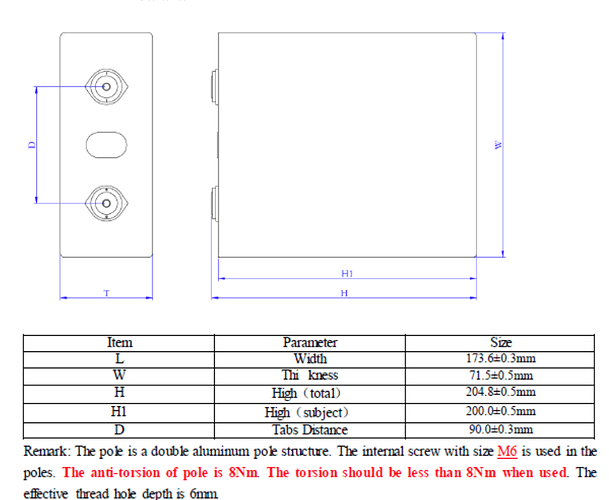
I am pretty sure that all the prismatic cells from 60ah to 280ah all have the same terminal spacing, the only variation being some use M4 and some M6. Mine are M6. I think using an M6 hole on a M4 bolt would be ok. I just love the idea of less wires. now all we need is wireless cell monitoring and this would be the prettiest gal on the block! Maybe little 433mhz rf modules, lol Lora, BTLE?

Thanks for all your hard work on this project, it is pretty awesome to say the least.

1 Like

On the subject of wireless, when you have dozens (hundreds?) of modules, you start encountering real problems with dropped packets caused by interference between individual transceivers, particularly with modules like the 433MHz or LoRa modules. BT isn’t immune to the problem either but I’ve less experience with it so not sure how it might be limited.

They all work great when there’s a small number of devices but fall apart as the device count per cubic metre of space ramps up :slight_smile:

Okay, I just measured the spacing and they are in fact 90mm centre to centre M6 bolts.

I was mostly sorta kinda kidding with the wireless option.It was more than in case Stuart came back with a “Check the next version” response, I could look like Nostradamus or something.

I have question with regards to the serial wiring, is there a polarity that I just somehow guessed correctly? or does it not care which way the wires go around? I was also wondering about using screw terminals instead of the JST type connectors. What is the pin spacing for the JST connectors? There seems to be many different sizes for the 2 pin terminal blocks. The reasoning behind this is that making the little cables is a PITA, and network cable like cat 5/6 already comes with a twisted pair designed for shielding signals, seems like a simple easy and affordable choice. Also means that custom lengths would be easier and nothing to heat shrink or tape up.
Thoughts?

@stuart Any thoughts on a board being made like this? I am thinking that if you could make this for the Prismatic cells, I would leave my current modules as is and buy and have made a batch of these ones with the new hardware and firmware.

Cheers, thanks for considering this.

Did you add the CAD file somewhere? I briefly looked at doing this as well but didn’t think jlcpcb can create a plated through hole large enough. I assume you were thinking about something similar to what Batrium does with their Blockmon cell monitors.

I was also wondering about using screw terminals instead of the JST type connectors. What is the pin spacing for the JST connectors?

The connector is specified here:

I wasn’t sure about the plated holes either until I saw what Stuart created for the Leaf Modules.

I looked everywhere for the cad, but couldn’t find it. I did however grab my caliper and measured my cell, I posted the terminal spacing which is all that should be needed.

I have been looking for screw terminals that are 2.00mm pitch and they are proving hard to find. Maybe if stuart is making a custom board he could design it for a common 5mm pitch screw terminal connector.
I like the idea of using some pre twisted cat5/6 wire, as it is designed to reduce interference and it is cheap like dirt!

Ok, I think should be whats needed.

One option is to make your own custom boards by downloading https://kicad.org and learn how to use it to modify the board yourself.

The title of this thread references Lithium Iron Phosphate (LiFePo4) batteries but
contains the text LTO.

Isn’t LTO a reference to Lithium Titanate Oxide?

1 Like

yeah, that was a typo, and I can’t edit it. :cry:

No problem. I fixed it for you.

1 Like

LiFePO4

@Michaelillingby, I made a board for the prismatic LiFePO4 cells cause im using Lishen 272Ah cells (also 89mm spacing with M6 screws) for my next project. The modules are on the way to me assembled from JLC. As soon as i know them working i will release my version of the DIYBMS v4 PCB.

3 Likes

that looks awesome.
I have questions…
first, that mosfet looks huge, did you do that to allow for higher discharge current? if so how much? what are the specs on this ?
Those M6 Vias look great too. could you share those files with me so I could take a look at what you’ve done?
Love the layout, it was exactly what I had in mind.
It would be great if there were some 3 inch jst plugs premade twisted etc.
thanks for doing this, again they look great!

When do you expect to receive them?

First i planed with an SOT8 mosfet but they are more expensive and i have still some some TO-252 mosfet laying around. The board is now planed with up to 4A discharge current thats also the reason why I’m not using the original mosfet form Stuarts design anymore. Now the biggest question for me is if the PCB can transfer the heat away from the resistors fast enough. Maybe i will also add a different version with the possibility of an external resistor.
The PCB should hopefully arrive in the next few days.
You can have a look in my EASYEDA libary: DIYBMS_Prismatic - EasyEDA open source hardware lab
Comments on the schematic are still the originals from Stuart so they are not correct for my design :smiley: as i said work in progress :slight_smile:

If heat dissipation is a problem, maybe a new layout with all the resistors grouped together so that a heatsink can be fitted.

My idea was to mount the PCB upside down and fit a Heat sink on the Backside of the PCB. Hopefully my cells are well enough grouped by resistance and i don’t think i will ever need the balancing. I’m only going to charge the bank to 3.45V per cell.