I’ve recently discovered this forum while searching the internet for my problem and saw similar posts regarding my problem.
I got a air-water Nibe heatpump f2040-12kW. The house is very well insulated and I have a comfortable temperature in the house but I believe my heat pump is not as efficient as should be.
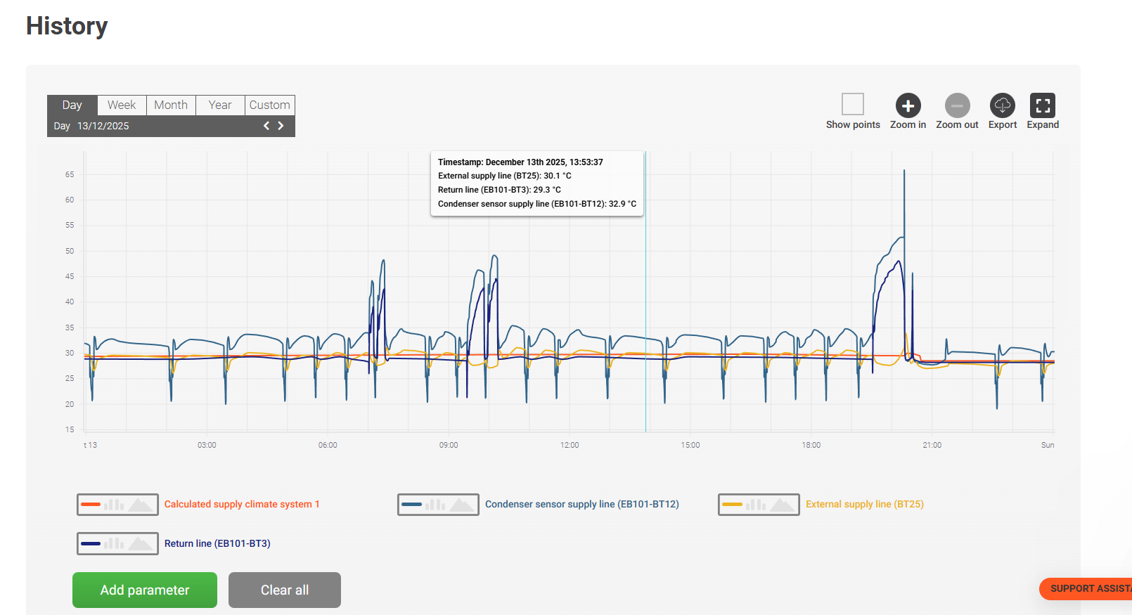
My main concern is that there’s always a quite significant difference between the BT12 (flow line sensor from the heat pump) temperature and the BT25 (flow line sensor to UFH). Sharing some graphs here.
When BT12 is around 32-33 degrees the BT25 is struggling at 29.5-30.0 degree, if the BT12 goes higher, like 34-35 the BT25 goes around 31-31.5. I also have a buffer tank of 180L but it’s used just as a tampon with only 2 pipes, flow and return.
When I bought the heatpump and start using it last winter, the situation was even worse, the difference between the two was constantly arount 5-6 degrees so I reached out to Nibe supplier and they did some changes in the system, one of these changes was to set the BT12 offset from SMO40 to +2.0 degree.
Another note here, the BT25 is often more close to the BT3 temperature which is the retun to heatpump, so this is very odd to me, the return that goes back to the heatpump to have similar value to BT25, there are situations where BT25 is higher with at maximum 1 degree that BT3 which to me is a red flag.
I’m going crazy with this system as I know it can do better. If someone would be interested to help, I can share more graphs and photos of the setup perhaps.
Hello and welcome to the forums. While NIBE systems are nothing like as common for contributors to these forums as say Daikin or Vaillant, there are several people with NIBE installations who have a very good understanding of how they work and I’m sure they will be happy to contribute here. As you noted, there are some other threads which relate to similar symptoms - I’m thinking in particular of this one and this one.
We now understand that the BT25 temperature sensor reading is one of the critical inputs to the NIBE “Degree Minutes” control algorithm, so it is important to have it provide a representative reading and you are right to be concerned it might not be correct. Since the BT25 sensor is fitted by the installer (rather than at the factory, like BT12) there is scope for it to be wired incorrectly or located in an unsuitable place - though as you’ve had the NIBE supplier back you’d hope they would have confirmed the wiring was correct.
Please would you share some further details about your installation:
You mention you have a 2-pipe ‘buffer’ which sounds like it is acting as a ‘volumiser’ tank.
Does that tank have a label - is it a NIBE UKV, for example?
Are you able to tell if that tank is located on the ‘flow’ or the ‘return’ side of the heating circuit?
Are you able to identify where your BT25 sensor is physically located, and post a photo?
Where there is a volumiser tank in the system, on the ‘flow’ side, it is common for BT25 to be located at the top of that tank, under a cover plate
Is that where your BT25 is located, or is it fixed to the pipework elsewhere?
You mention that BT25 is your “flow line sensor to UFH”
Is the UFH your only source of heating or do you also have radiators?
Is there just one UFH manifold or several?
Is there a separate circulation pump on the UFH manifold(s)?
The NIBE control algorithm calculates a Target Flow Temperature, S1, and then keeps track of how the Measured Flow Temperature, BT25, compares with that Target - including during defrosts and DHW cycles
Would you be able to post a graph showing S1 together with BT12, BT25 and BT3?
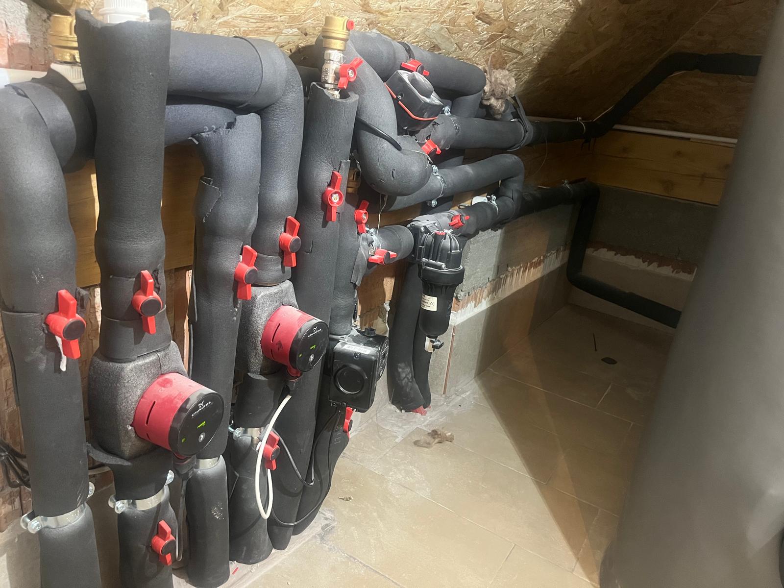
A few general photos showing the layout of your pipework would also be helpful.
Hello David and thank you for your time looking into this.
Does that tank have a label - is it a NIBE UKV, for example?
No, It’s a Cordivari buffer
Are you able to tell if that tank is located on the ‘flow’ or the ‘return’ side of the heating circuit
I don’t know to be honest, it looks like it’s at the end of the ‘setup’ with flow and return connected to it. Please see photo
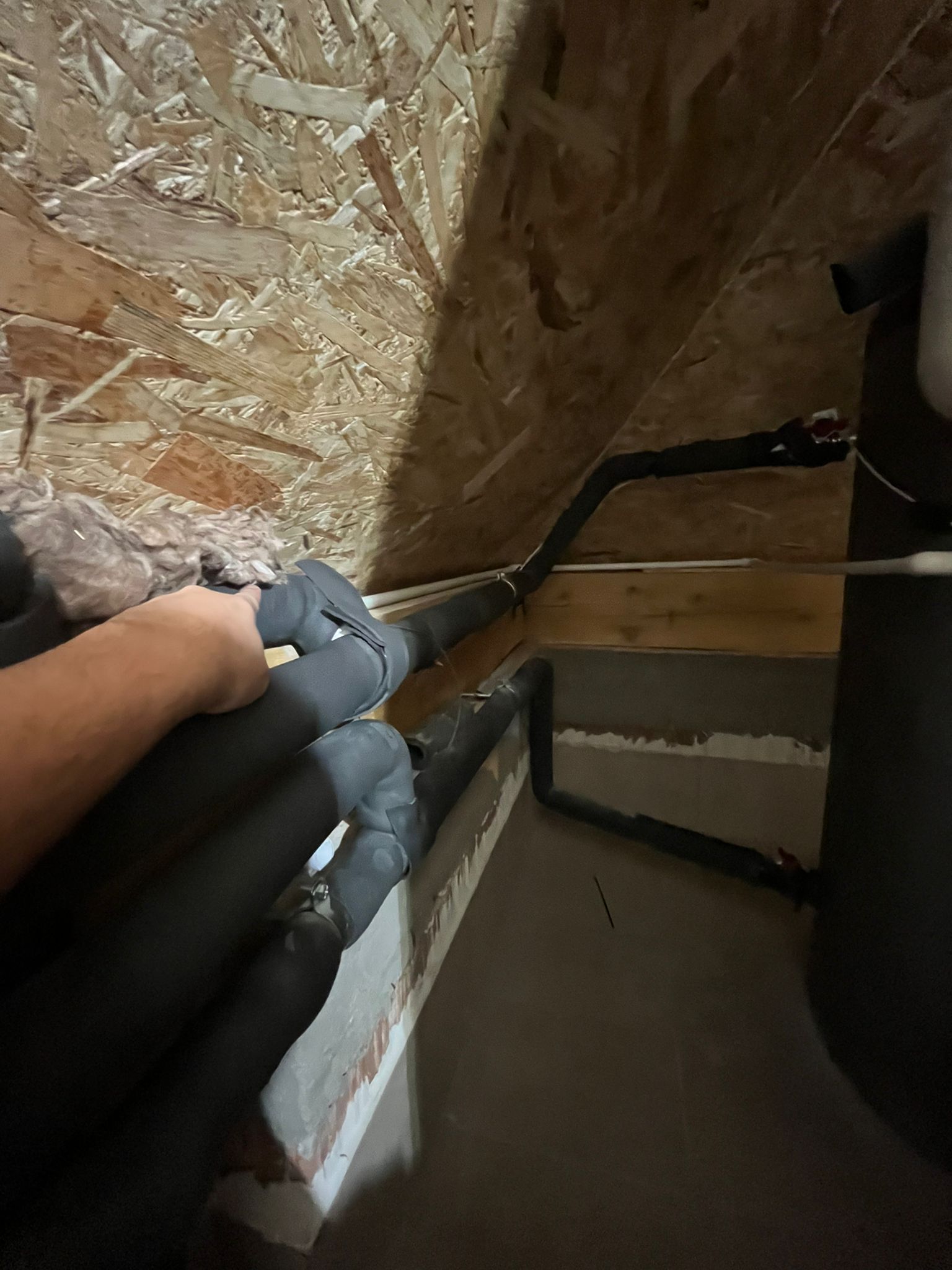
Are you able to identify where your BT25 sensor is physically located, and post a photo?
Yes, the BT25 is fixed on the pipework, basically from what I understand, I have the main flow trom the heat pump which goes into the buffer, at the middle of it I have a TEE pipe, one goes to the buffer the other one goes to the 2 UFH manifolds. Please see photo where is located
What doesn’t make sense to me.. if I have the main flow from heat pump and on the same flow I have that TEE pipe where it goes 2 ramifications, one goes to the buffer, the other one goes to the manifolds. What’s the logic here? Does it mean that at the TEE pipe I will have a mixing? I have used a thermocamera and before the TEE (where the main flow from heat pump is) I have a temperature of 32 degree let’s say, after the TEE (the ramification that goes to the buffer) I have 27-28. Then it means that the 2 pumps from manifols will get the water mixed and it is obvious it’s colder? Why my pumble would make such a setup? It doesn’t make sense to me.. What’s the point of the heatpump to make water at 32 degree and later on in the system to mix it with some cold water.
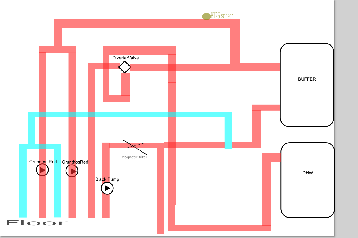
Please see attached general photos of my installation.
Thanks for your comprehensive responses to my questions. You do appear to have an unusual plumbing arrangement - especially for the buffer / volumiser tank.
Your graph showing S1 etc. confirms the NIBE control algorithm is (correctly) making BT25 follow S1 “on average” - but as you noted before, BT25 is often closer to BT3 (Return) than to BT12 (Flow) so the Flow temperature is higher than it needs to be, which will be lowering your COP.
Indeed. The Flow from the heat pump ought to go directly to the UFH manifolds, without being mixed with colder (Return) water.
My suspicion is that the interaction of the three circulation pumps is causing water to flow in unexpected directions so that BT25 is seeing more ‘Return’ water than ‘Flow’ water. Moving BT25 to a different section of pipe might be a partial solution - but since that won’t change the way the Flow and Return are mixing that would probably just make the house too cold.
Generally speaking, when there are multiple secondary circulation pumps (i.e. your two red Grundfos UFH pumps) - in addition to the primary circulation pump (i.e. the black one in your photo) - it is preferable to have a Low-Loss Header or some other form of “hydraulic separation” which makes the water flow more predictable.
Your pipe insulation is much better than most installations I have seen but that makes it difficult to understand all the pipe routes and connections from one photograph:
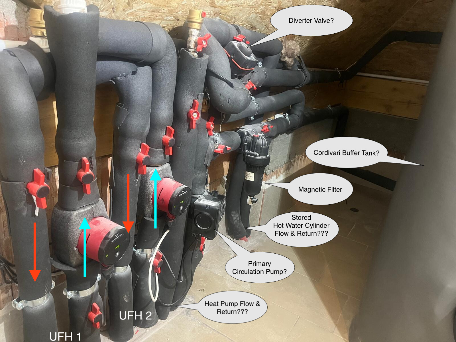
The UFH connections are clear enough and I believe the two red Grundfos pumps will be pumping ‘upwards’. (I have the exact same pumps and their flow is ‘away from’ the electrical connection; you also have an ‘up’ arrow marked on one of your pumps.)
I didn’t ask about stored hot water (DHW) before but based on your graph and your photo that looks like a typical NIBE arrangement, with a Diverter Valve on the heat pump Flow feeding a stored hot water cylinder - which I presume is located elsewhere, connected via one of the pairs of pipes which disappear into the floor?
The heat pump Flow and Return must then be on the ‘other’ pair of pipes into the floor - but is that the one near the UFH pipes or the one by the Magnetic Filter?
Do my notes on your photo match your understanding or do I have some of them wrong?
It would be very useful to have a simple schematic sketch which shows the pipework connections - especially how the buffer tank is connected and the source of the water flowing past BT25. It’s currently not clear to me whether the buffer tank is plumbed as a ‘bypass’ between the Flow and Return or if it’s ‘in series’ on one or the other.
Hi David. Is it possible to upload a video here? Currently I am not able to. I think with a video I’ll be able to capture everything. To make a schema I am not sure it will be right as I am making assumptions which is what
I think you should be able to, maybe the video is too big? The default attachment upload size limit is 10MB - I don’t know if ours is the same or different.
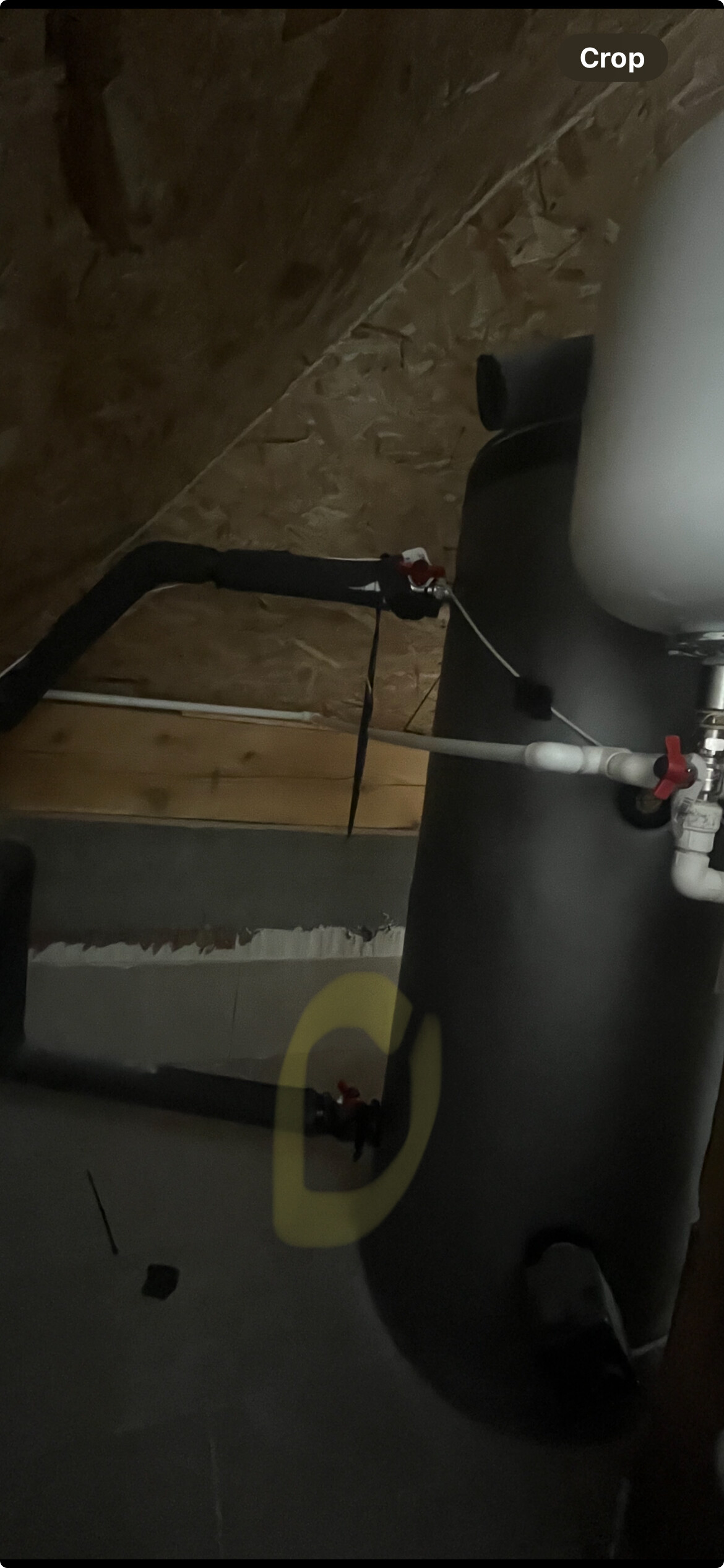
Please see the attached video, the fist tank you see in the video is the DHW, behind it it’s the Buffer.
Worth mentioning that the installation room I’m filming is located in the attic. The heat pump external unit it’s next to the house at the ground, so there are approximately 15meters till it gets to the installation room, from the instalattion room it goes down to the 1st manifold which is 1st floor and 2nd which is on groundfloor
I have also tried to draw a schema manually and one with a digital tool.
Thanks. The video isn’t loading for me but the schematic is enough to go on for now.
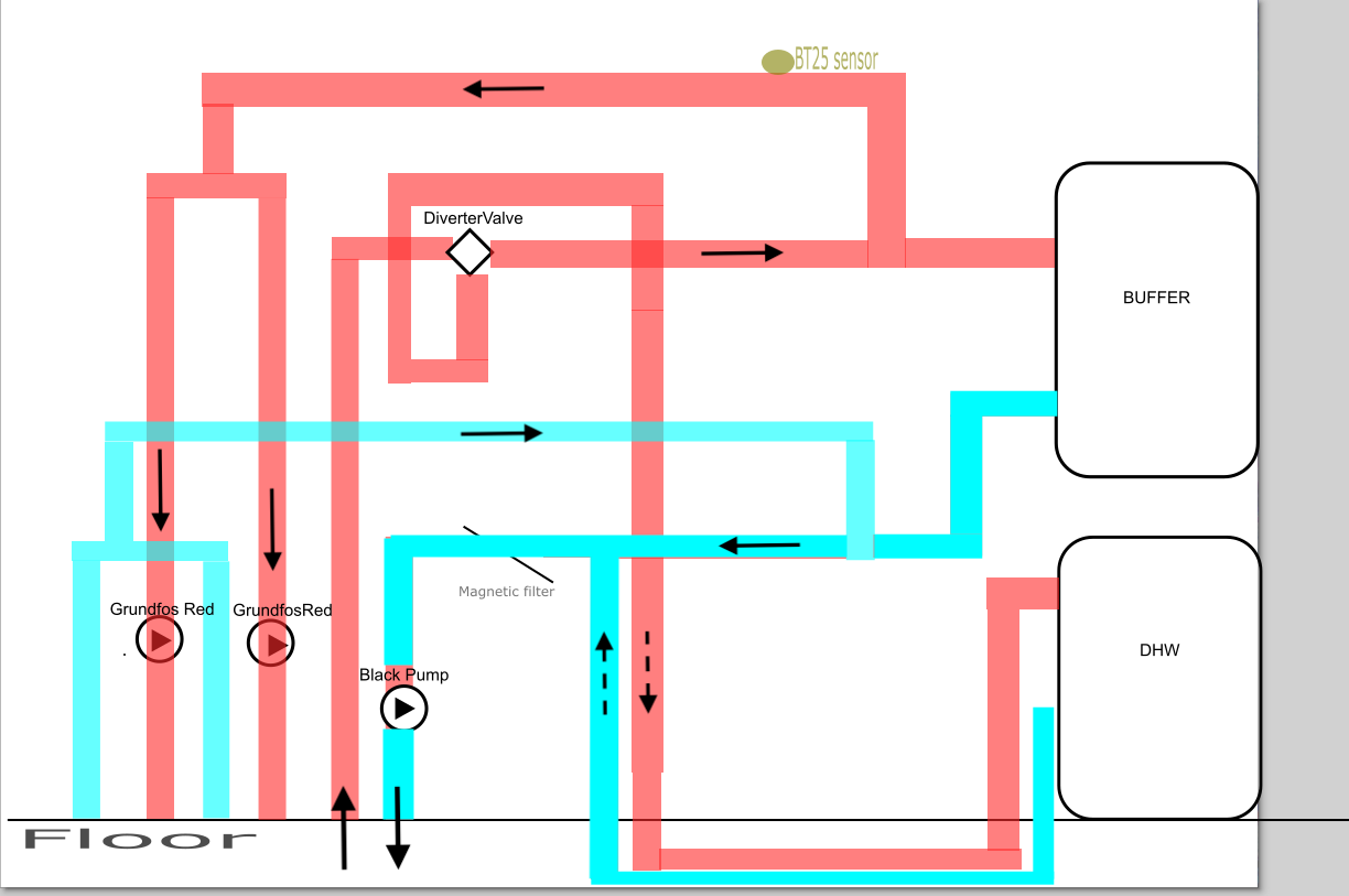
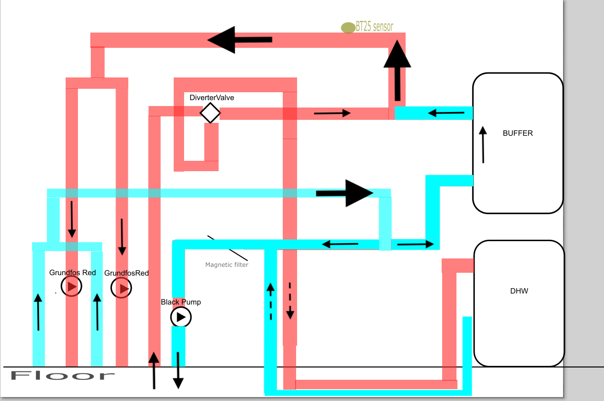
I’ve added some more colouring to extend what you had for Flow (Red) versus Return (Cyan) and some arrows for ‘intended’ flow direction. Typically the Black pump is on the Return to the Heat Pump - and the Diverter Valve must be on the Flow from the Heat Pump, which tells us which pipes are which.
One obvious question is whether the two red Grundfos pumps are indeed pumping ‘upwards’ as I previously thought, or if they are pumping ‘downwards’ as seems to have been intended, based on the pipework layout
If these two pumps are pumping ‘upwards’ then they’re effectively on the Return from the UFH, not the Flow to the UFH - which would mean BT25 is seeing the water after it has been through the UFH - which could certainly explain your low BT25 reading.
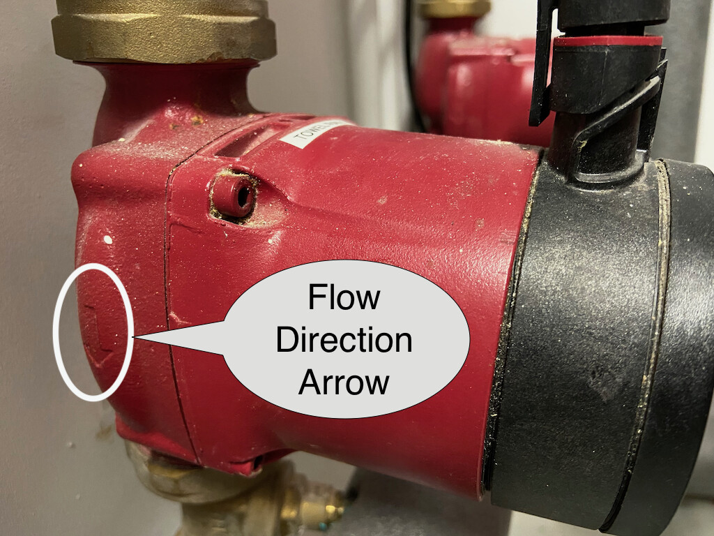
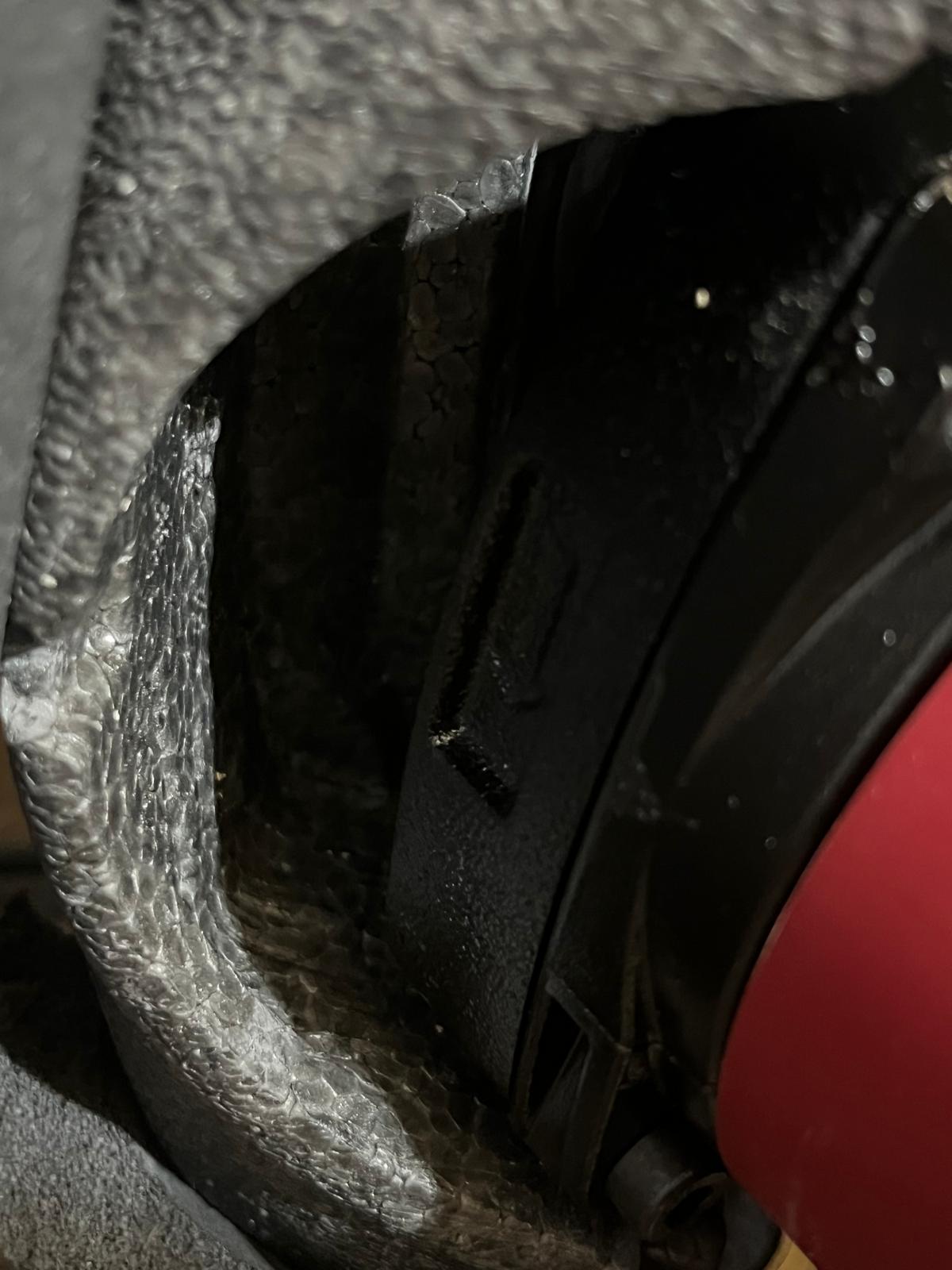
To confirm the pump flow direction, you will need to check the arrow cast into the metal body of the pump. That’s under the grey polystyrene insulating cover. Here it is on my pump (which doesn’t have an insulating cover).
The video doesn’t load for me either if I’m on mobile, it does work if I’m using the laptop. I’ve uploaded the video here Download - UploadNow.io
I’ve had a chat with chatGPT whereby I have shared the above schema and according to chatGPT
The short and clear answer: NO, the buffer tank is NOT installed in series. It is installed in parallel (by-pass / shunt).
I am wondering if I can close the buffer tank valves so that the water will go straight to the UFH manifolds and by doing that I should see an increase in BT25. Is there any risk in doing that? I’d like to test it. Do you have any other suggestions?
OK, so the two Grundfos pumps are pumping in the “correct” direction (downwards) (and my previous annotated photograph with the red and blue arrows was wrong).
That suggests you have a situation more like the following, where there’s some ‘Return’ water coming back from the Buffer Tank, mixing at the ‘Flow’ Tee junction and reducing the temperature at BT25 (and for the UFH):
(The logic behind that conclusion is that there are two Red pumps running in parallel for the UFH, but only one Black pump for the Heat Pump - and as you noted before the Heat Pump is 15m away, on the Ground Floor.)
Closing the Buffer Tank valve(s) would be useful as a test, to see what effect that has on the readings for BT25, but note that will result in additional flow through the Heat Pump heat exchanger which it won’t be expecting. It’s possible that might trigger an alarm condition in the NIBE controller.
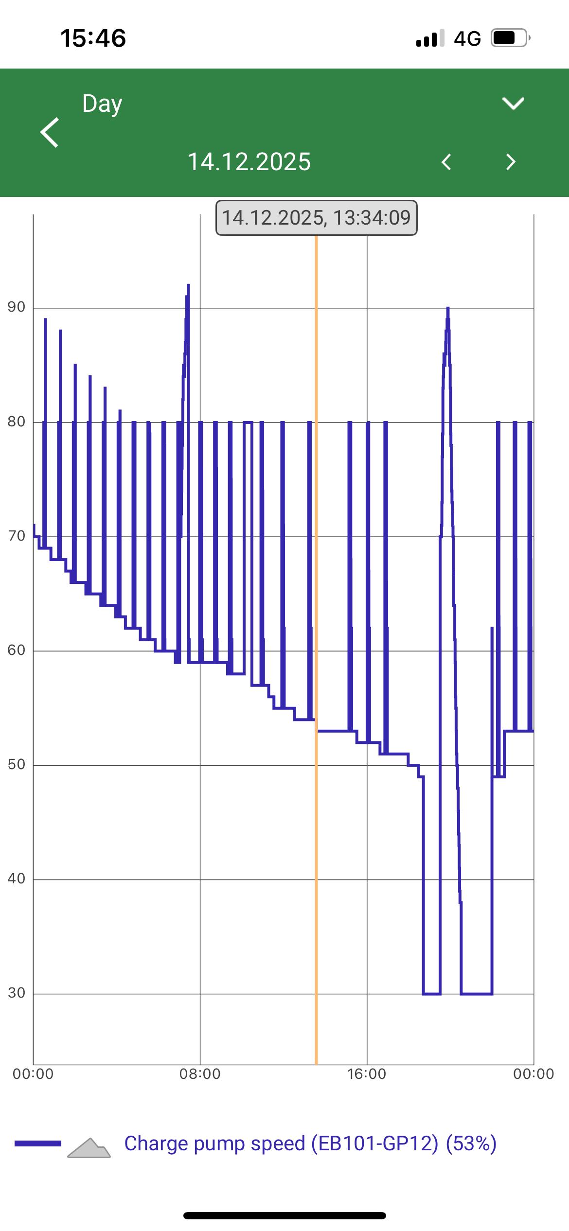
I’d be interested to see how ‘fast’ the Black Pump is being driven by the NIBE controller. Are you able to graph the data for that? In NIBE terminology that is the Charge Pump and there should be a reading called something like “Charge Pump Speed” which is a percentage value.
Typically, the NIBE controller adjusts the speed of the black pump to maintain a specified Temperature Difference (DeltaT) between Flow and Return, but there are configuration settings in the NIBE menus to have it run at a fixed speed instead or to set Minimum and Maximum speed values.
Attaching 2 photos with GP12 charge pump. I keep this under observation in myUpLink view, usually in ‘heating’ mode it runs between 50-60%.
In DHW it runs faster, 80%+. During ‘defrost’ it also peaks to 80%. Worth mentioning that during defrost BT25 drops with almost 2 degrees.. so what I have achieved during a heating cycle it gets lost during defrost and it has to pick it up again in next heating cycle.
The GP12 pump it’s set on ‘auto’ with min speed 15% and max speed 100%, speed during waiting time 30%. I was thinking as well to switch it to manual and set a fixed speed starting with 75% and see if there’s any improvement. Would you recommend that?
Also worth mentioning that at the beginning of the year when I started to doubt about efficency after monitoring the heat pump last winter, the plumber came and he closed a bit the return valve from the buffer (see photo). The situation was even worse before doing that, the BT25 was significantly colder but he also switched the location of BT25 (cannot tell where it was located before)
Before these changes BT25 was strugelling to achieve 26 degrees and could exceed that only with additional heating.
Another thing worth mentioning, I have used the ‘cooling’ mode this entire summer and the situation was the other way around. BT12 was running at 18-20 degrees whilst the BT25 was ‘warmer’ indicating 22-23 degrees
Thanks for the GP12 Charge Pump Speed graphs. I was wondering if the pump speed might be really low (e.g. 20%) but it seems to always be over 50% while it’s heating - which isn’t crazy, but since the Charge pump is being ‘overtaken’ by the two Grundfos pumps it should be higher than 50%.
I would suggest trying a much higher speed while it’s heating. Mine typically goes to 100% (in ‘Auto’ mode) during a heating cycle, and it’s more like 60% during a DHW cycle, so there’s no issue with it handling a high speed. (The other option is to reduce the target DeltaT setting so it automatically runs the pump faster while heating. I changed my DeltaT from 7 to 4.)
Another thing worth checking is the speed setting on the Grundfos pumps. Those are normally configurable into different modes and speed settings. If those were running less fast they would use less power and be better-matched to the Charge pump - although you will need to ensure you’re getting enough flow through the UFH manifolds (which hopefully have flow meters for each ‘zone’).
That fits with colder water being taken from the ‘Flow’ side of the Buffer to help supply the UFH circuits. Closing that valve would add more resistance to any flow from the Buffer, meaning more water would be taken from the Heat Pump instead.
That also makes sense: BT25 is getting a good share of ‘Return’ water mixed with the ‘Flow’ (and in Summer the ‘Return’ would be warmer, raising BT25).
The grundfos pumps are set to maximum as I can tell, 3 green lines. I don’t think lowering this would be good as I barely have 1.5l/min on most ufh circuits, few at maximum 2l/min and they are fully opened.
So I guess I will try the following, even tho I am a bit afraid to change anything by myself
Increse the gp12 speed and monitor, if this doesnt have any improvement i will
Shut down the buffer valves and see what happens
I think I will get in touch with the plumber and try to convince him once again that my system is not as efficient as it should
I agree. 2 l/min is a good target flowrate for each UFH zone so if you’re below that already you should not lower it any more.
That also sounds sensible to me. The Buffer arrangement and the Tee fittings seem like an odd way to have installed the system. The Buffer in particular - it appears that really isn’t helping at all.
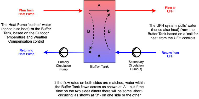
If there are some spare ‘ports’ on the Buffer your plumber might be able to easily reconfigure it as a four-pipe (or six-pipe) Buffer - to operate more like this, which I think would help:
Where can I find this configuration in SMO S40? I’ve tried searching the whole menu and internet and I couldn’t find it
As an update, I’ve closed both valves from the puffer for 24h and I could see an increase in BT25, more closer to BT12 but I could also see that the debit from UFH circuits decreased.. If before I’ve had a 1.5l/min for vast majority and few with 2l/min, after closing the puffer, I could see a decrease to 1l/min for vas mojority and few with 1.3-1.4l/min.
Also, another observation, after closing the puffer, the GP12 speed decreased to minimum allowed in my config which is 15%..
I was not sure about these changes in behavior so I’ve reopened both valves halfway through and I could see the debit from UFH circuits going up again.. At this point in time I am not sure how it’s better, with valves completely closed or back to my original setup
I have the previous generation of controller (SMO 20) so it might be in a different place on your system.
According to the Installer Manual for the SMO S40 it should be under Menu 7.1.6.2 - FLOW SETTINGS, CLIMATE SYS which has a setting for “Delta Temp at DOT”, described as:
dT at DOT is the difference in degrees between supply and return temperatures at design outdoor temperature.
The reduced flow through the UFH with the Buffer Tank valves closed is a concern - although that might be partially explained by the 15% Charge Pump speed. I suggest setting a higher minimum Charge Pump speed to see if that helps increase the flow - or set a lower DeltaT which ought to have the same effect of increasing the Charge Pump speed. If a higher Charge Pump speed doesn’t help increase the flow my recommendation would be to leave the valves partially open to maintain the flow through the UFH.
Your findings all seem to confirm the understanding that water is being taken from the Buffer Tank to increase the Flow past BT25 - so I’m confident that understanding is correct.