My Journey to an efficient ASHP

Hello,

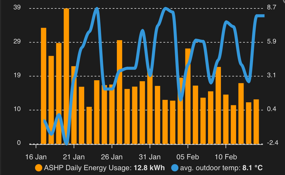
As with so many others, my ASHP is misbehaving and consuming more than I think it should. I am sending data to EmonCMS and my graphs don’t look like all those posting their good performance all over social media etc.

My Setup

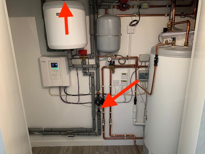
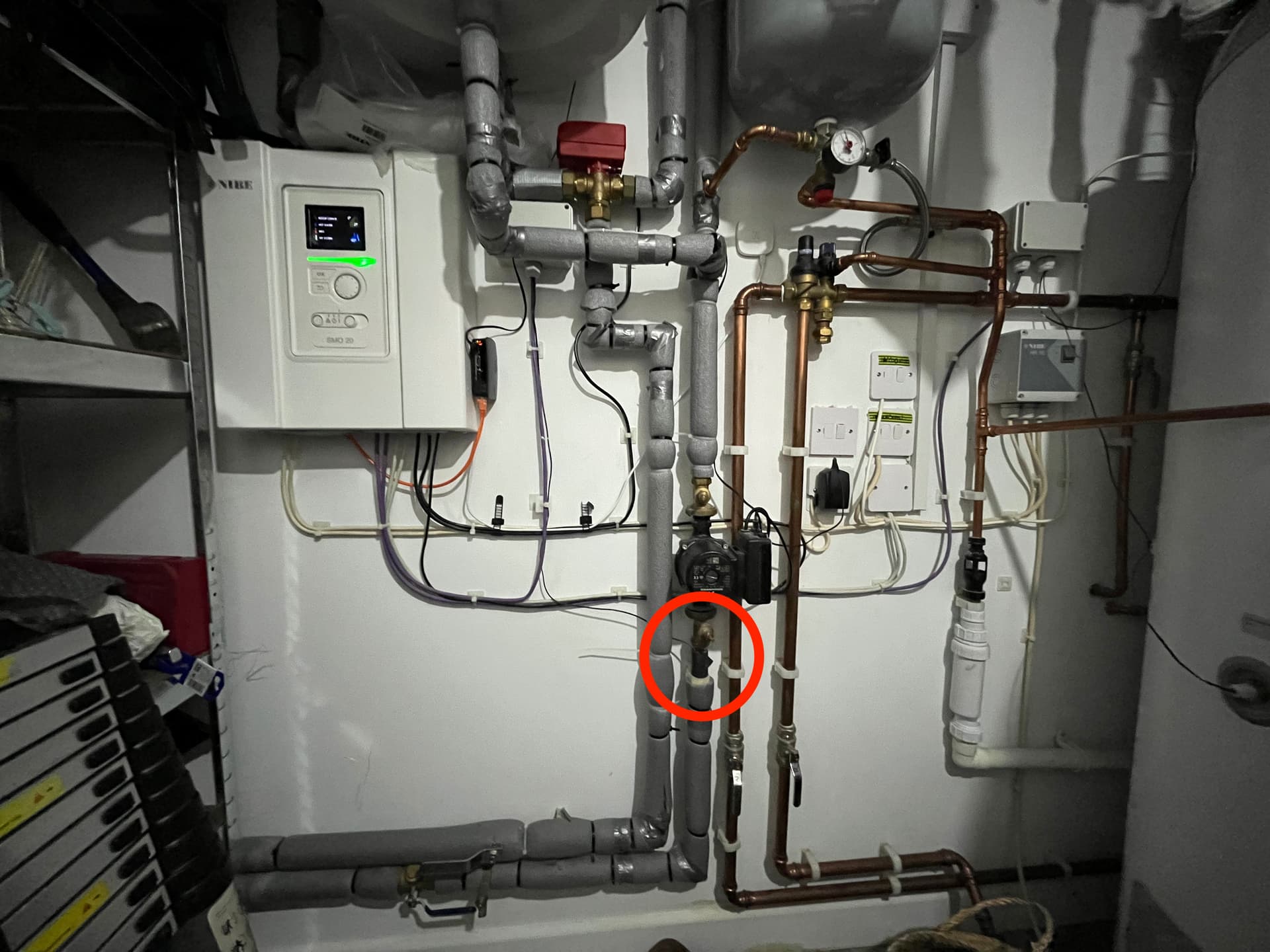
2017 completed detached 4 bed in Southern Scotland. 8kw Nibe F2040 with SMO20 controller ASHP, seems to have buffer tank and 200l hot water storage and some other stuff in there too:


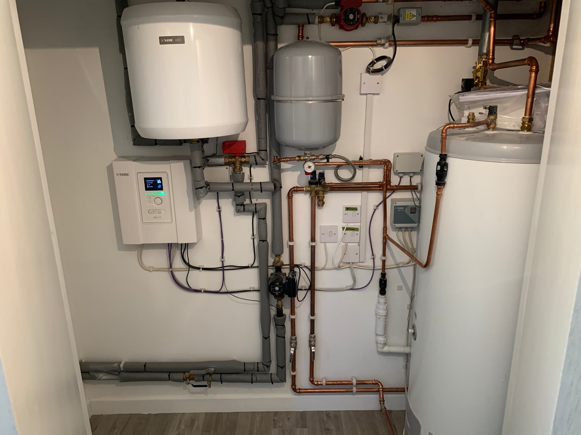
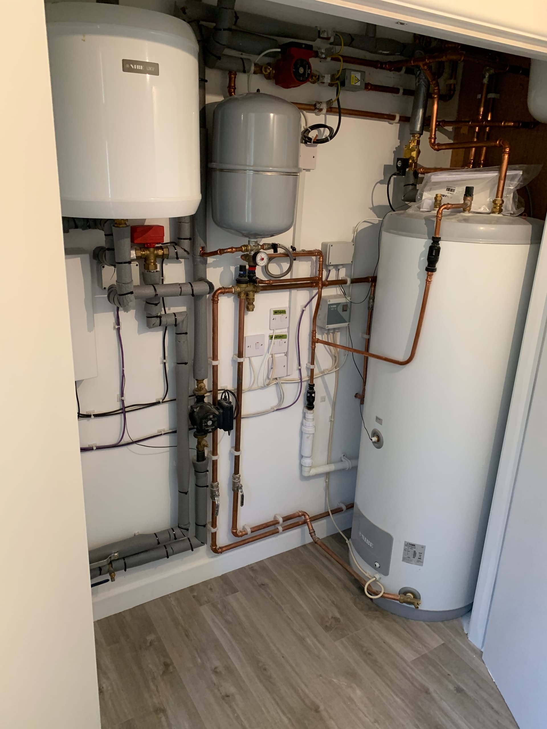
House appears well insulated, has MVHR working well with rads and towel rails upstairs and wet UFH downstairs. 6kw solar array and 10kWh battery storage.

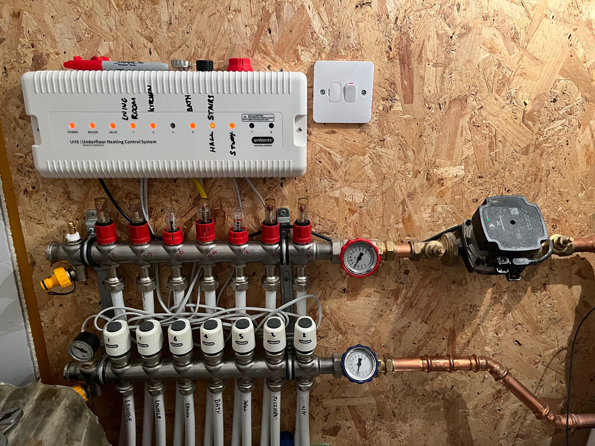
I’ve been building a smart home using HomeAssistant and the integrations have (mostly) helped shed light on where all all the energy is being used. In my haste I did install Tado too, but since watching Heat Geek videos, specifically not to ‘zone’ and increasing the surface area to heat, have reconfigured much of this to ensure the flow through emitters is maximised; ie, only closing valves if the room is super hot, usually due to solar gain etc.

My Issues

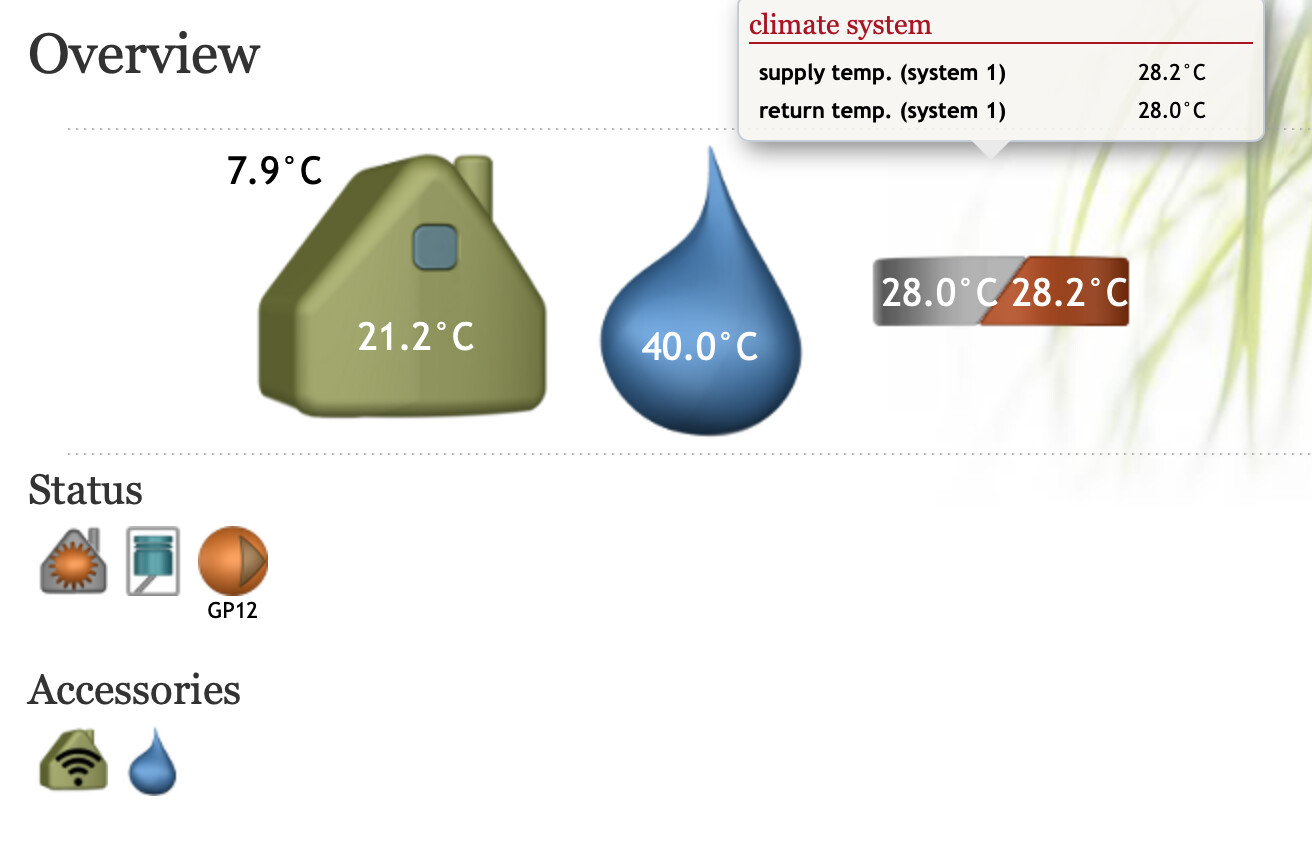
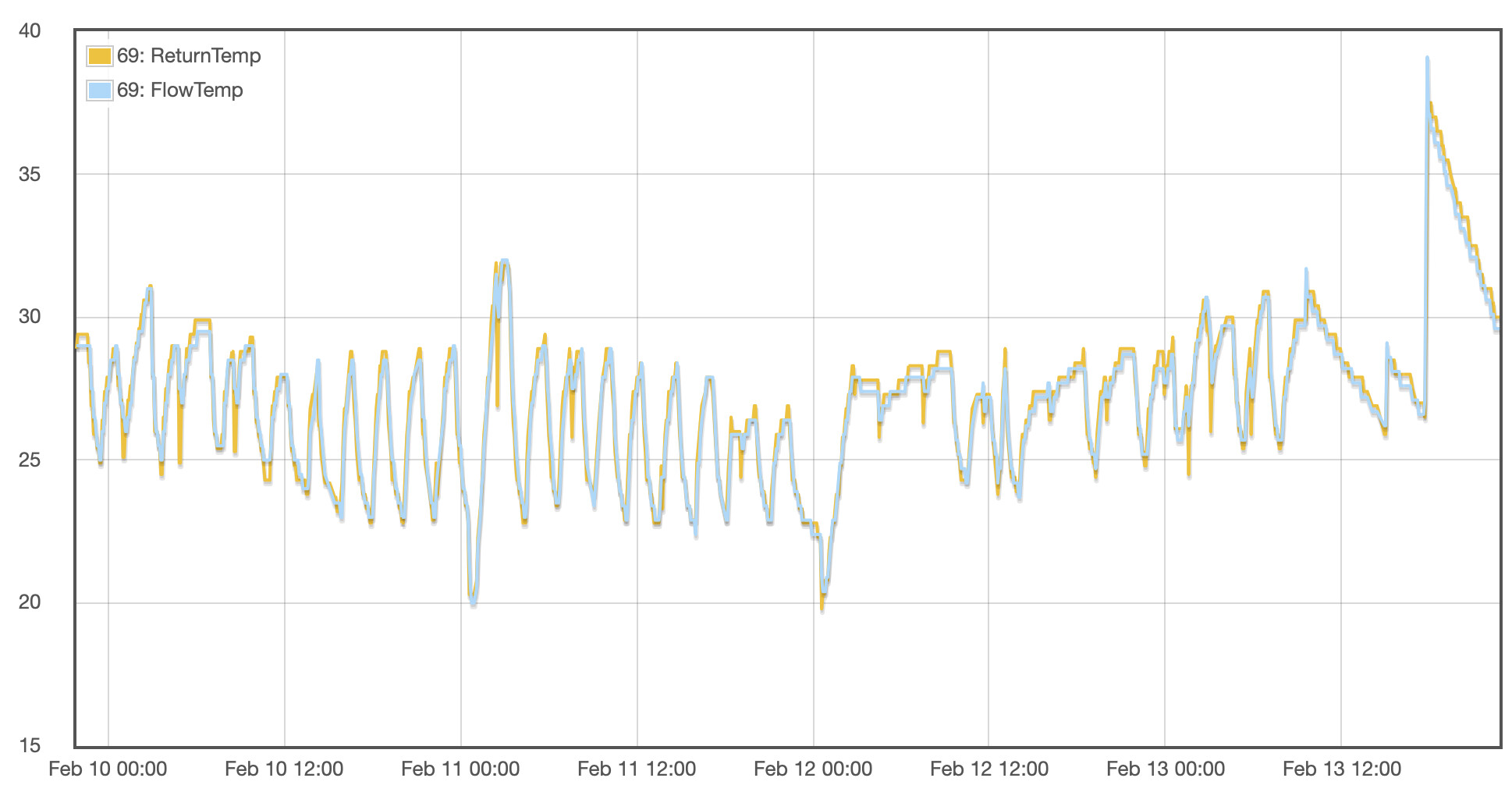
The ASHP is reporting very close flow and return temperatures. The UFH suffers from this also, but less acutely. There is maybe 5/6 degrees difference in flow and return for UFH running the system at about 25-30 degrees.
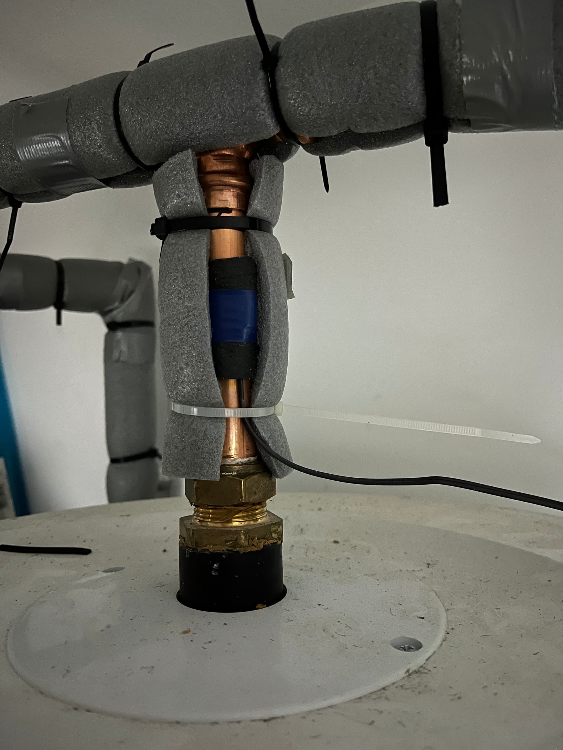
The ASHP flow and return are always very close. When the ASHP is providing heat it is not unusual for me to see the return higher than the flow (!!) and the boiler in a regular cyclic pattern.

I am in the process of balancing and fillings the loops on the UFH with balancing the radiators next on the list.

It is not unusual for our 10kwh batteries to be flat before lunch due to the usage of the ASHP which just can’t be right. The house is plenty warm enough, indeed I might even try a lower curve, but at such low flow temps I suspect the problems with deltaT flow / return will only be exacerbated…

So, why isn’t my heat pump emitting the heat it is generating and what can I do about it to make the ASHP work as they are intended?

1 Like

Hello Nick,

That sounds like a decent installation, though as you say the dT is very small.

Some quick questions to get the ball rolling…

  1. how much electricity is being consumed by the heat pump each day?
    and are you able to measure how much heat in being generated?
  2. where are the temperature sensors located?
  3. how is the buffer tank plumbed into the system?
    is it adding only volume or also providing hydraulic separation?

Do you have a system diagram?

Do you have data from a Heat Meter etc so you can use the HeatPump App?

Is the UFH fitted directly to the HP/Buffer, or does it ‘blend down’?

I’d also as how they are connected (outside of the pipe for instance or in pockets)?

No system diagram I’m afraid, but I can access all the bits and provide model numbers if helpful?

There’s no heat meter just yet, it’s on my shopping list. I am using the HeatPump app without that field enabled.

I assume the UFH blends, but doesn’t seem to want to go much above 30, regardless of what the WC curve is asking the ASHP to produce.

No idea on temperature sensor location, the information I’m reading is from the Nibe Uplink, so I assume it to be correct.


(Yes, it’s too hot in here just now, hence dialling down curve by 1 point!)

Hi Tim,

Thanks for getting back to me. I may need some help with the answers.

1 - Heat pump energy usage (vs exterior temp) which doesn’t actually look terrible for the time of year, however as soon as the temp dips much below 3degs, the usage skyrockets, with constant short cycling which I hope to capture in MyHeatPump app

2 - No idea I’m afraid, I’m reading data from the Nibe uplink

3 - I can take some photos, or muddle through this, which is the buffer tank? The nibe UKV tank above the SMO20 in my pic?

Cheers

Assume nothing (a mantra I live by as assumptions are the mother of all Foul ups)!

Can you post a photo of your UFH manifold? I posted a lik to a blending version on this thread Cost of running a Nibe ASHP , controlled by SMO20 for DHW only - #37 by borpin. basically it limits the temp to the UFH and draws heat from a store as and when needed.

So the WC is more impacting the ASHP than the UFH. It does do a bit of it’s cold outside so need to come on earlier, but I suspect that is about it.

UFH works best at a steady state (IMHO), so I never let mine get really cold in winter and I then only need to trickle feed heat into it (low deltaT) and maintain about 28°C flow temp. Most ASP systems tend to connect the UFH directly to the HP. Personally I think this is wrong and a common source of the HP cycling.

Looking at the flow/return numbers you’re getting from it, I’m not so sure they have been correctly fitted. dT should be somewhere between 2 and 6, looking at stats for other heatpumps. Given that your house is “plenty warm enough” and electrical consumption isn’t excessive, I think we can guess that the heatpump is working as expected. From the chart you posted, it’s likely that one of them is measuring correctly. Follow the thin wires from your controller… they’d usually be on the two pipes that come in from the outside unit.

I don’t have experience with Nibe heatpumps, but @dMb may have some insights.

Yeah, maybe. I’d expect you’ll find 2 or 4 pipes connected to it.

1 Like

Just to note this is pretty much the same as your other thread Monitoring Energy Usage of heat pump (Heating and Hot water)

Much better to keep it in one place.

Hello @TheMiddle36uug you might be interested in @Zapaman’s dashboard who also has a Nibe Emoncms - app view dashboard, Dom has spent a lot of time tuning his Nibe to get it to run more consistently and might be able to share some insights.

Always worth putting some numbers on that if you can. E.g what was your annual gas consumption if you were using gas before the heat pump? what did the heat pump installer quote your annual consumption to be? what was your expectation of the consumption and how does it compare with actual consumption?

2 Likes

Thanks @TrystanLea. Typically the issue seems to start at around 3 degrees ambient temperature, where I see consistent short periods of cycling at around 3kW. ASHP energy usage can be anywhere between 25 - 60kWH once we’re below 3 degrees, or thereabouts which isn’t infrequent here in Scotland.

The figures on that dash look much better than my own! I have enabled public viewing of myHeatPump App, but can’t see the share function, or it just the URL?

Thanks

Can you post a photo of your UFH manifold?

Flow Meters all replaced/cleaned today, just need to make sure all the loops are full. Some balancing of the UFH has definitely helped the place even out, but I was expecting to see a larger deltaT on the two gauges there, which is priestly deltaT of 4 at 30degrees. Is that acceptable?

Thanks for the photo, so it is fitted directly (unless there is a blending valve to the right of the pump).

Blimey, mine has been fitted 10 years an I have never done that!

@Timbones Thanks,

Follow the thin wires from your controller… they’d usually be on the two pipes that come in from the outside unit.

OK, followed a cat5 cable which led to a junction box with two thin wires coming out of it.

40639009d87449ac9c6ccab4f915809d295b4605_2_666x500

One wire heads to the top of the system and is fitted to a pipe above the white tank labelled Nibe UKV

From the website

(NIBE UKV 40, 100, 200, 300 and 500 are buffer tanks used together with heat pumps to increase the volume of water in the system for more stable operation)

This is the fitting, I am assuming this is the ‘External Flow Temperature’ sensor:

The other wire heads towards the bottom of the system and was simply taped to the pipe with some adhesive foam insulation tape again. (? Correct), just beneath what looks like a pump


. It looks to be located on the way out of the system, although the pipe doesn’t feel much cooler than the one one it’s left (as you look at it) actually.

Edited to say, looking at the state of the lagging I wouldn’t be surprised if they are both reading the ambient temperature of the closet all the kit is in! :frowning:

unless there is a blending valve to the right of the pump

Nothing to the right of the pump in that room, which is under the stairs, not the same area as the ASHP…

Blimey, mine has been fitted 10 years an I have never done that!

Mine were that bad I couldn’t read them, even with a LED torch behind them so gave them a good clean to assure myself the flow rates were correct.

I am leaving no stone unturned! ha.

Those sensors look like they were fitted where the length of wire allowed them to be fitted!

@Timbones will correct me if I am wrong, but as close to the ASHP flow and return would see to be what is needed.

Get some heat conducting paste and aluminium tape. Make sure the and the pipe is properly lagged. Unless you want to heat that room, lag every pipe (poor lagging bugs me and not leaving enough room for lagging bugs me even more!).

[edit]
Are these the flow/return for the ASHP?

image

I feel your pain, you should have seen the state of the lagging behind the actual ASHP. But now, behold, tis a thing of beauty! (To me at least…) Armaflex 25mm self-sealing.

I did think about doing the inside as well, but any heat loss should just be moved around the house by the MVHR, plus it dries the clothes really well!

That said, if it is detrimental to the performance of the ASHP then it will need to be rectified.

I’ve looked at the installer manual but can’t see where Nibe recommend to install the sensors. I can easily relocate them once advised where might be best.

Edit:

Are these the flow/return for the ASHP?

Yes, they are the pipes to the ASHP outside.

Hi Nick,

I’ve got a NIBE GSHP and I’ve been helping @prwv with his NIBE ASHP which has the same controller as yours. NIBE use codes to identify their different sensors - you can see them on NIBE Uplink; things like BT6 (Hot Water Charging temp), BT25 (Buffer Tank Flow temp) and BT71 (Heating Return Temp) which are wired back to the SMO 20 Controller but the outdoor Heat Pump unit (which probably appears as a ‘slave’ on NIBE Uplink) should be recording things like BT3, what the Heat Pump sees as its Return Temp.

If you can reference those codes it will be easier to understand what they’re intending to be measuring (plus the NIBE installation docs reference those codes for the physical wiring terminals on the controller).

Yep, just post the URL.

Hi David,

I saw the other thread, what a power of work! Really gave me hope that I can the best out of this thing.

I’ve become familiar with the register codes, as that’s what HA uses to import the information from the uplink, but taking a closer look at the info in MyUplink I am plotting:

  • 40071 (Flow Temp) → BT25 External Flow Temp
  • 44055 (Return Temp) → EB101 - BT3 Return Temp

As discussed last night, I’m not sure of the quality of the placement of these two sensors and would be grateful of advice if they need relocated

Yep, just post the URL.

https://emoncms.org/app/view?name=MyHeatpump&readkey=be35f4ed5ddc09c1e79df1dcec1e274a

Thanks for that URL and the ‘BT’ codes Nick.

The NIBE installer manual for the F2040 https://www.nibe.eu/assets/documents/25327/231846-7.pdf lists the sensor locations in the outdoor unit. BT3 is in there; “Heating medium return line”.

The red and green lines on your graphs are so close they can’t possibly be Flow and Return (the difference between them is roughly 0.3 degrees). They’re either both Flow or both Return; my hunch is the latter - so if your green line “ReturnT” is BT3 (which is a factory-installed sensor so pretty much guaranteed to be correctly wired) and your red line “FlowT” is meant to be BT25 it’s the latter I’d be suspicious of.

There’s a separate manual for the SMO 20 controller: https://www.nibe.eu/assets/documents/23940/231758-7.pdf which shows how sensor BT25 (on top of the UKV Buffer Tank) is meant to be wired to the X2 connector.

I’d expect the sensor on the pipe near the black pump (which is on the return to the heat pump) to be known as BT71.

If you’re sure your red line is plotting what NIBE Uplink calls BT25, then I reckon the sensor wiring is wrong - but you’ll have to trace it back to the X2 terminal block in the SMO 20 to be sure.

3 Likes

Thanks David,

The lines I’m plotting are definitely what the SMO20 thinks BT3 and BT25 are, and you’re right they are too close to be correct.

Nibe Uplink UI shows the figures to be as close:

Interestingly I’ve just spotted that GP12 Charge Pump supply figure (which doesn’t appear anywhere else in the uplink interface) has a slightly higher and likely more accurate supply temp, and also matches the return temp.

I’ll investigate the wiring and post an update. Thanks for the pointer!

1 Like