Hi all
After recently moving into a new house I have inherited a NIBE ASHP installation, after being very surprised by the electricity usage in the house I have begun to suspect the ASHP might not be running at optimum efficiency. Unfortunately I have no background data from previous years or knowledge of costs prior to an ASHP in the property, I also have very little detail on the installation, design or commissioned efficiency of the system. I have started to understand how the systems are installed and what is happening (thanks to NIBE Uplink and the excellent python examples from @dMb but I am now at a loss where to go next as I do not have contact with the original installer. The installation was originally done in 2019. After reading two excellent threads on the problems with installations of NIBE systems I am really hoping the knowledgeable people on here can help diagnose and suggest some next steps.
The summary of the installation is as follows:
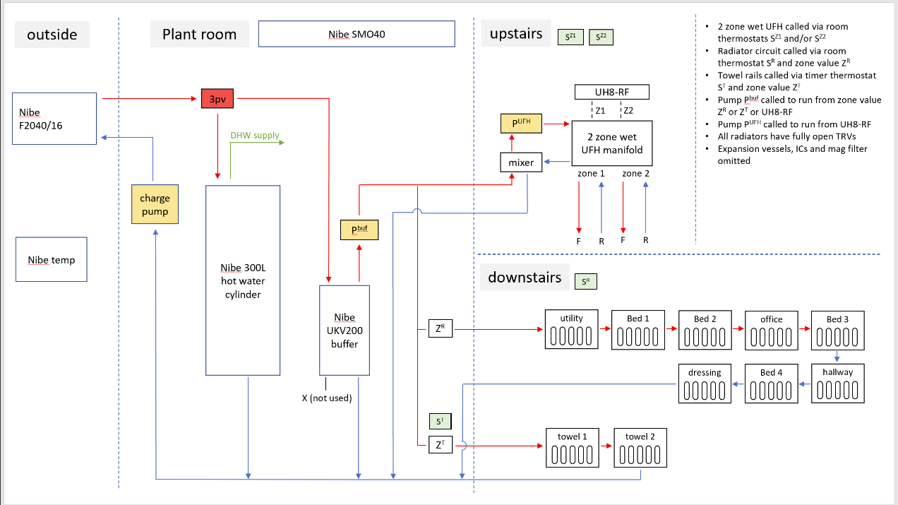
NIBE ASHP F2040-16 with a 300L DHW cylinder and a UKV100 buffer tank
Upstairs: wet underfloor heating with two zones, a mixer and pump on the UFH manifold. These zones are controlled via two room thermostats which open the actuators, turn on the UFH manifold pump and a circulation pump connected to the UKV100 buffer tank
Downstairs: radiators zoned off using a zone valve and controlled via a hallway thermostat. The thermostat opens the zone valve which in turn triggers a circulation pump connected to the UKV100 buffer tank. There is also a separate towel rail circuit with a similar zone valve set up (although the zone valve is currently broken and removed so this is effectively not zoned)
There is no electrical connection between the UFH, radiator or towel rail control wiring and the ASHP. The ASHP seems to be running purely on weather compensation when it is not charging the DHW
The UFH thermostat upstairs is set to 22 degrees all day with a 2 degree night set back. The thermostat downstairs for the radiators is set to 19 degrees all day with a 2 degree night set back. The system seems to be able to get the the house to temperature but some days feel a lot colder than others, I suspect this is due to huge variances in the heating water temperature at any given time (see problems below)
A schematic I have drawn up of the installation (as accurate as I can be from tracing pipes and wires) is as follows:
I am yet to fit energy monitoring equipment to the ASHP circuit and as yet do not have a heat meter, at this stage monitoring for the SCOP seems a little premature. I also have photos available.
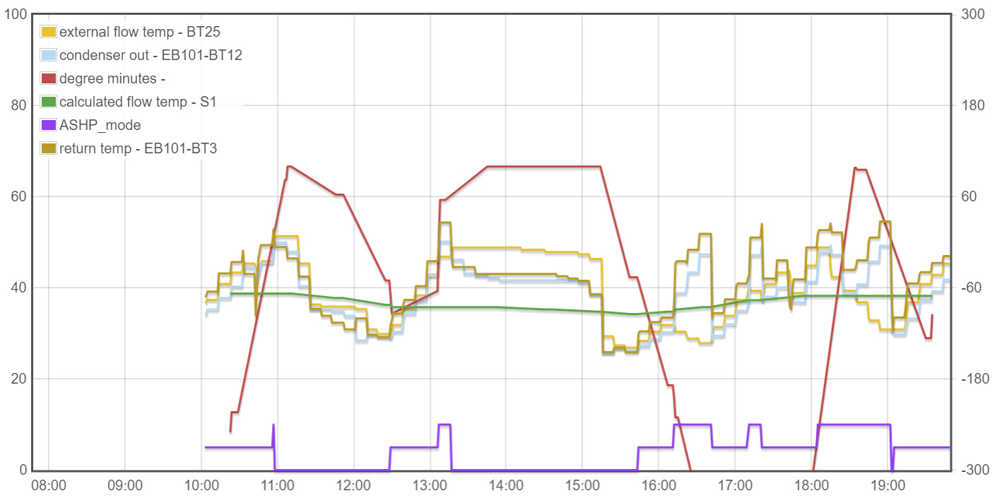
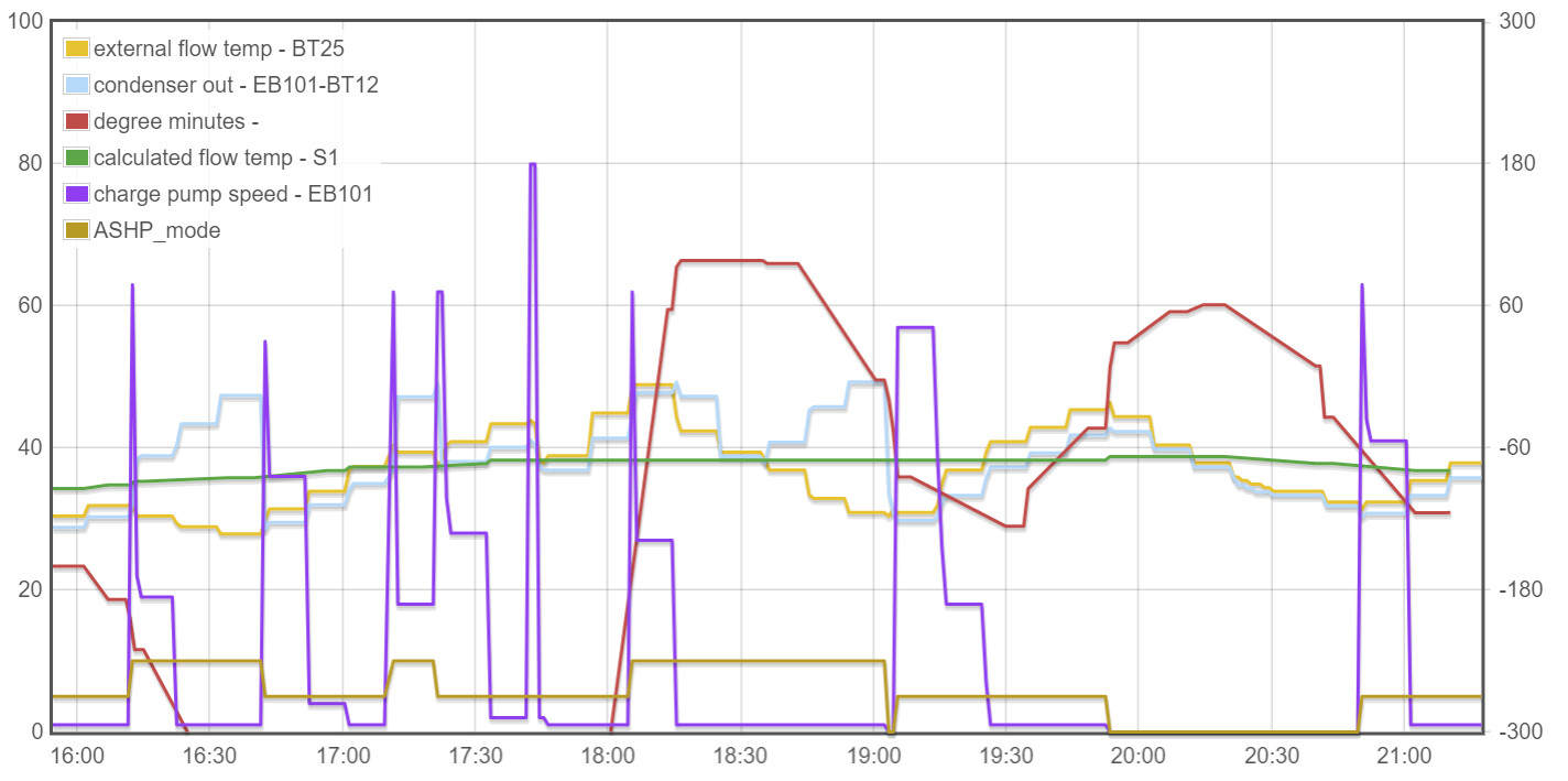
My observations to date come from analysis of the NIBE Uplink data and physical observations in the house (lots of checking pumps and touching radiators…). A screen shot of 12 hours running from today is plotted below:
I have the following observations and potential problems, I expect there might be more than I am not yet able to identify (the ASHP_mode is a signal I have added and is derived from the NIBE Uplink API (0 is off, 5 is heating mode and 10 is DHW mode)
The return temperature is consistently higher than the flow temperature as seen as the ASHP, this is using the factory sensors (BT3 and BT12) and as read from NIBE Uplink
When the heating thermostats are calling for heat the same fluid can have 2 circulation pumps and the ASHP charge pump all running at the same time, there seems little hydraulic separation between them. Often the charge pump will only run at 1%
Due to no electrical connection between the heating controls and the ASHP I assume the ASHP is using weather compensation and to do that I understand it needs heating flow and return sensors (BT25 and BT71). The system does not have a return flow BT71 sensor installed and this shows blank on NIBE uplink. The flow sensor (BT25) is buried into the top of the UKV100 buffer tank and seems to follow the same pattern as the return to the heatpump. When the ASHP has been in DHW mode it creates a large increase in temperature detected from the buffer tank flow. The temperature in the buffer flow is far higher than the required calculated temperature from the weather compensation (S1 on NIBE Uplink)
The outdoor sensor continually reads about 5-6 degrees higher than the real outside temperature and also the temperature as measured at the ASHP and shown on NIBE Uplink (EB101-BT28). If this outdoor sensor is being used to calculate the target flow (S1) based on the weather curve then it could be calculating wrong, although I suspect I have bigger problems than this right now.
The system seems to do a lot of DHW charging and often heating is switched to hot water for a short period.
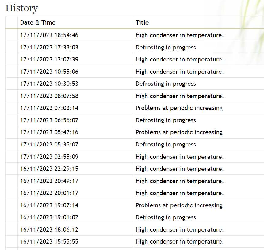
On the NIBE uplink history page, I am observing a lot of information messages and observe that the AHSP is going into defrost mode multiple times a day even though the outside temperature is well above freezing (8-12 degrees this week)
I can’t help with your heat pump, but I’ve promoted your privileges by a step so you should be able to post photos and more attachments now. Any problems - just ask.
There are many questions, and hard to know where to start, but I’ll pose a few to get going.
Are the thermostats NIBE or 3rd party? (They may be only switching in heat load if weather compensation is configured, but still worth knowing)
Can you add pipe sizes to the great schematic if possible? (Buffers are generally a bad thing, but if designed well by competent company, there may be a good reason (e.g. 8mm microbore pipes)
DWH sounds like it’s on a “reheat” whenever temp drops setting. Can this be changed initially to a schedule overnight and maybe another midday if needed? If the tank is cold throughout you’ll likely get better CoP efficiency and keep on space heating longer.
Also, so many pumps and zone valves! You probably (need data to do the maths) don’t need the pumps etc. depending on requirements. (Eg: Octopus removed our UFH pump, zone valve, mixing valve and thermostat controls - just balanced loops now )
They are 3rd party, they are Heatmiser RF type thermostats to a RF switches and then some wiring logic takes care of turning things on. The NIBE ASHP has no knowledge of them as far as I can tell
I shall update but generally it seems 15mm OD from the wall into the radiators but I suspect there is 12mm OD in the circuit too as the flow and returns by the buffer are all 12mm. The wet UFH flow and return is 22mm OD copper
I have tried to schedule this in the NIBE SMO40 controller and activated the schedules, however it still “charged” when it wanted and after periods of heavy DHW usage (e.g shower). I might need someone who has more experience than I with the NIBE system to tell me how to do this, I would be happy to do it as we have a regular DHW demand but I couldnt get it to work.
Hi Sam. Welcome to the forum and thanks for such a clear and comprehensive introductory post. I’m pleased to hear you’re finding my Python scripts a useful basis for pulling data back from NIBE Uplink.
There’s a lot to take in but the one thing that leaps out to me as being very odd is your comment about the charge pump often only running at 1%. Mine flips between 20% and 100% depending on whether the compressor is running or not, and yours needs to be way higher than 1%. Would you be able to include the Charge Pump speed on the graph (or a separate graph) please, so we can see how that relates to the other parameters?
The Flow temp (BT12) being lower than the Return temp (BT3) is also odd - and might be related to the Charge Pump speed. In automatic mode, the Charge Pump speed control algorithm aims to achieve a specified delta-T across Flow and Return.
Given the multiple pumps in play, your 3-pipe Buffer is presumably what the original installer had in mind to do hydraulic separation, but if the Charge Pump is barely running, P^BUF is likely doing more of the work (when its zone valves are calling for heat).
You don’t need BT71 to do Weather Compensation. I’ve not got that sensor and pretty sure the other NIBE customers on here don’t either. Effectively the controller is just comparing the actual flow temp (from BT12 and / or BT25) with the calculated (think of it as a ‘target’) flow temp (S1) and trying to get them to match, on average (which is what Degree Minutes is all about).
Out of interest, do you know if the heat pump was originally installed to replace a boiler? There’s little reason to have a mixer on the UFH loops when the heat source is an ASHP running on Weather Compensation.
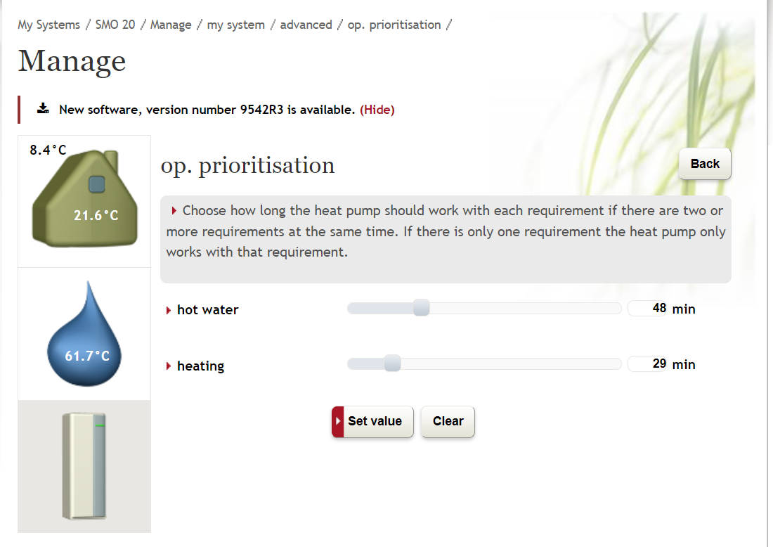
If the heat pump is switching between space heating and hot water too frequently you could try adjusting these parameters (under the op. prioritisation menu)
Hi David, thank you. This is such a useful place of information and help so I am glad I have joined. Apologies for the information overload on the first post, I learned a lot from reading the other NIBE posts so thought I would try answer as many of the questions from those as I could.
It does spend a lot of time at 1%. the same graph is below with charge pump %, the low flat lines are all at 1%. It seems to have a “burst” and then settle down to 1% and it does this for DHW or heating
ok, so I guess having flow and return all over the place and a buffer tank that seems to follow the temperature out the heat pump irrespective of mode isnt going to help the weather compensation
I am not 100% sure but the original bungalow didnt have the heat pump and then the upstairs was added with wet UFH at the same time as the ASHP installation. I do know the plumbing and UFH was installed by a separate installer and they may have just put a standard wet UFH system in without knowledge of the ASHP. I have the mixer set to the hottest it can go to try and minimise with return water.
thank you. it seems I need a subscription to do this…I am happy to get one but I will see if I can narrow down on some other problems first and then look at this to optmise.
Indeed. Thanks for adding those Charge Pump Speed readings; they’re nothing like what I’d expect to see.
I suggest we start with the basics: how / why is the Flow temperature (BT12) showing lower than the Return (BT3)? An issue with those readings is always going to confuse the Weather Compensation and Pump Speed control logic.
As you noted already, those are factory-installed sensors within the outdoor unit so it’s hard to believe the actual sensors are installed incorrectly, but could their cables be swapped on the way to the Controller?
The Charge Pump would have been fitted by the installers. You might as well double-check that’s pumping the right way round.
The load (UFH, radiators) are being switched off (more than on compared to during the day), so less heat being lost, yet your heat pump likely (from what we know) doesn’t have any idea it can switch to a lower flow temp during setback periods to better match the thermostat target.
On this one, if the thermostats are not actually used for heat demand (communication with the heat pump) but instead are switching the load (UFH, radiators) on/off, I guess you should consider tactically scheduling an offset drop on the weather compensation curve, with the same schedule. This is until more strategic changes are made to be clear.
You could use trial and error with the leaving water/flow temperature drop/offset amount in degrees C (obviously timing to match the thermostats schedule).
Or do you know/have access to the weather compensation curve on the controller? A photo may help us better understand this if you’re not sure.
I’m not familiar with NIBE, so maybe others with a NIBE can assist, but this video may help in the above point if you have the same/similar controller.
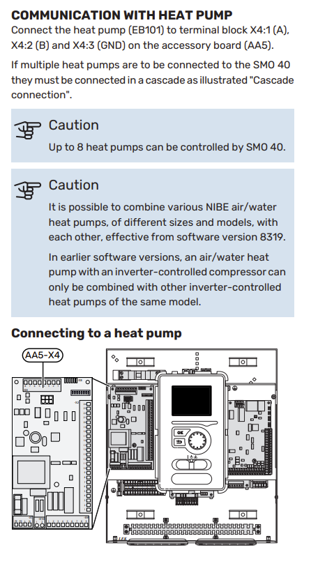
I have previously thought about the wiring and investigated, it does seem there is no individual wiring coming in for these two sensors. There is a communication cable coming in from the ASHP to the SMO40 controller, I have assumed this is using something like RS485 to communicate control and information data between the SMO40 and the ASHP. This is installed as per the manual and communications seem to work between the two
You @etchelsa can also set a minimum charge pump speed in the NIBE controller settings that might help circulate a bit more heat around the circuit for now while you sort out the pumps / pipework / blend valves etc.
Terminals labelled A and B does indeed imply RS485 and if it’s that rather than individual cable-pairs which could have been mis-wired that suggests BT12 and BT3 are reading the right Flow and Return temperature sensors.
Do you have some way to check the Flow and Return pipe temperatures to confirm if BT3 and BT12 are accurately reflecting the flow and return temps?
Yes that’s correct. Those two pipes leave through the external wall, go through an outdoor boxed in area to the flow and return at the heat pump. Im currently trying to remove the boxing (easier said than done) to trace those pipes.
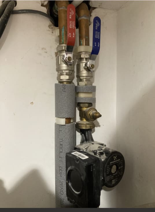
From the photo, the pipe on the left goes to the 3 way valve diverting water to the DHW or buffer tank
The pipe on the right is connected to the returns and i am assuming the charge pump is pumping upwards. This might be a wrong assumption? I cannot get closer to it as it’s behind the DHW cylinder.
I am tracing the pipes because it does appear that the flow out the ASHP connects to what I believe is the return leg containing the charge pump. This is unless the pipes cross in the 3-4m of boxing between the ASHP and the wall entry point shown on the photo.
It would be good to rule out a cross-connection of flow and return. Assuming the pipes are copper all the way you might be able to do that with an electrical resistance / continuity multi-meter - if you can get to both ends of both pipes and run a temporary wire to complete the circuit.