An update from me. This journey isn’t yet over, although I’ve made remarkable progress thanks to the contributions from members of this forum, again, thank you.
Since relocating the BT25 sensor to capture both flow to the heating circuit and the return fed through the buffer I think I am seeing slightly better performance, albeit it hasn’t been as cold… Yet, we’re in Southern Scotland.
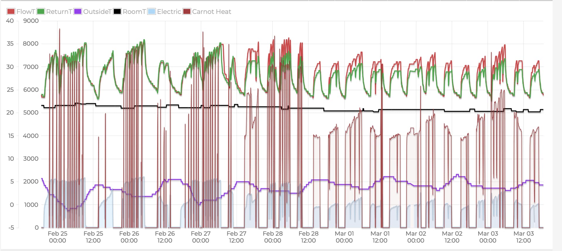
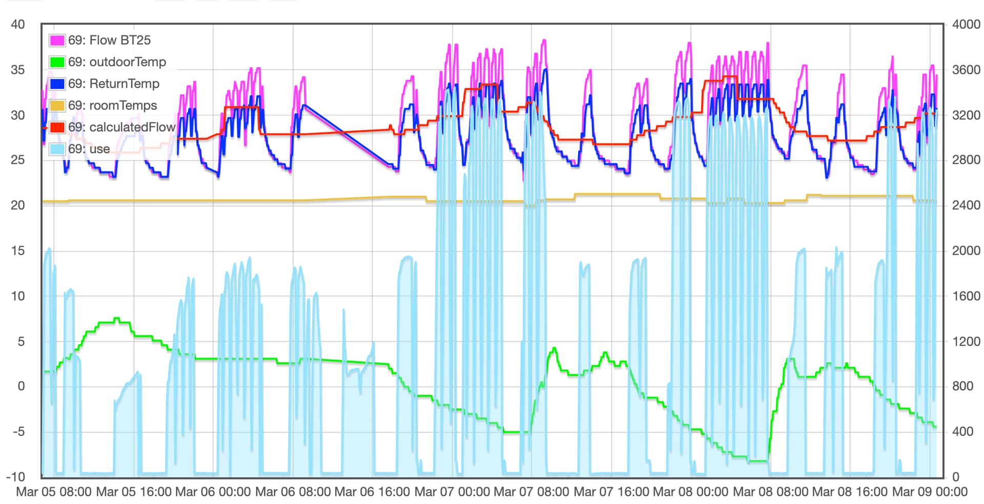
I updated myHeatPump app with the BT25 flow sensor and you can see my results here and:
It was the afternoon of the 27th Feb when the sensor was repositioned.
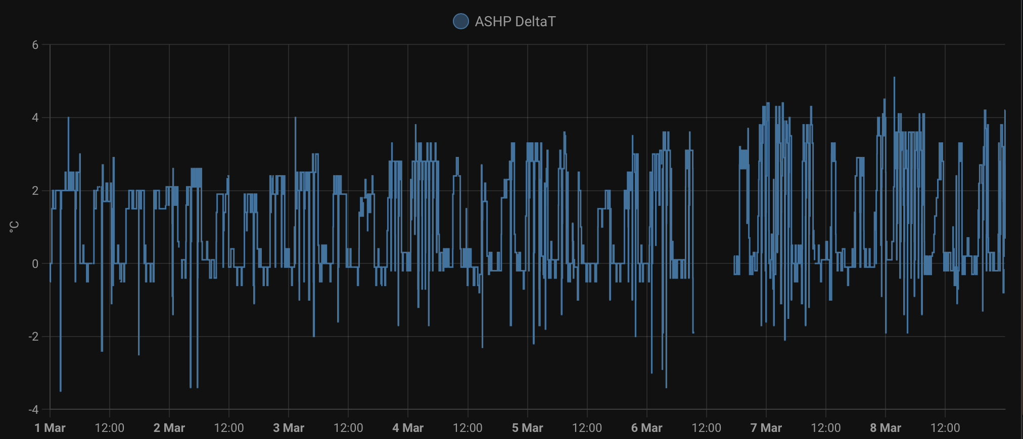
So, I think the overall usage is lower but I am still only seeing a deltaT of 2-3 degrees running between 27 and 32 degrees flow.
Can this be improved?
UFH fully serviced and balanced, rads still need doing but are there gains to be had with pump speeds, compressor start DM values etc?
Tweaking the DM value for the compressor start is only really changing whether it does a few long cycles or a lot of short cycles, and that’s more about compressor longevity than efficiency (fewer starts makes for a longer life - though that’s much more an issue on older systems without an inverter drive, like my F1145).
Did you get anywhere with your installer? I’m still curious about “what were they thinking” - especially with the Buffer Tank and the Pumps on both the Radiator and UFH circuits, with no attempt at Hydraulic Separation.
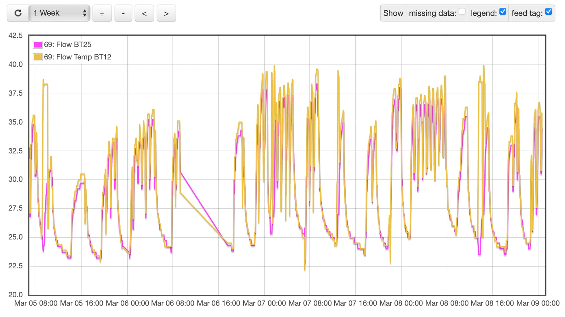
I wonder if the relatively low deltaT is evidence of ongoing ‘dilution’ of the Flow to the Rads & UFH, with Return water coming up through the Buffer Tank. Is BT12 significantly higher than BT25?
What about the Charge Pump Speeds - are those now more respectably high (like 75% or more)?
It’s also worth checking what deltaT the system is being told to aim for; that’s set in the Service Menu (near to where the manual Charge Pump speed settings are). The ‘auto’ setting on the pump speed is meant to vary the Charge Pump speed to deliver the requested deltaT (though clearly it can’t go above 100%, or the configured upper limit on speed, if that’s less).
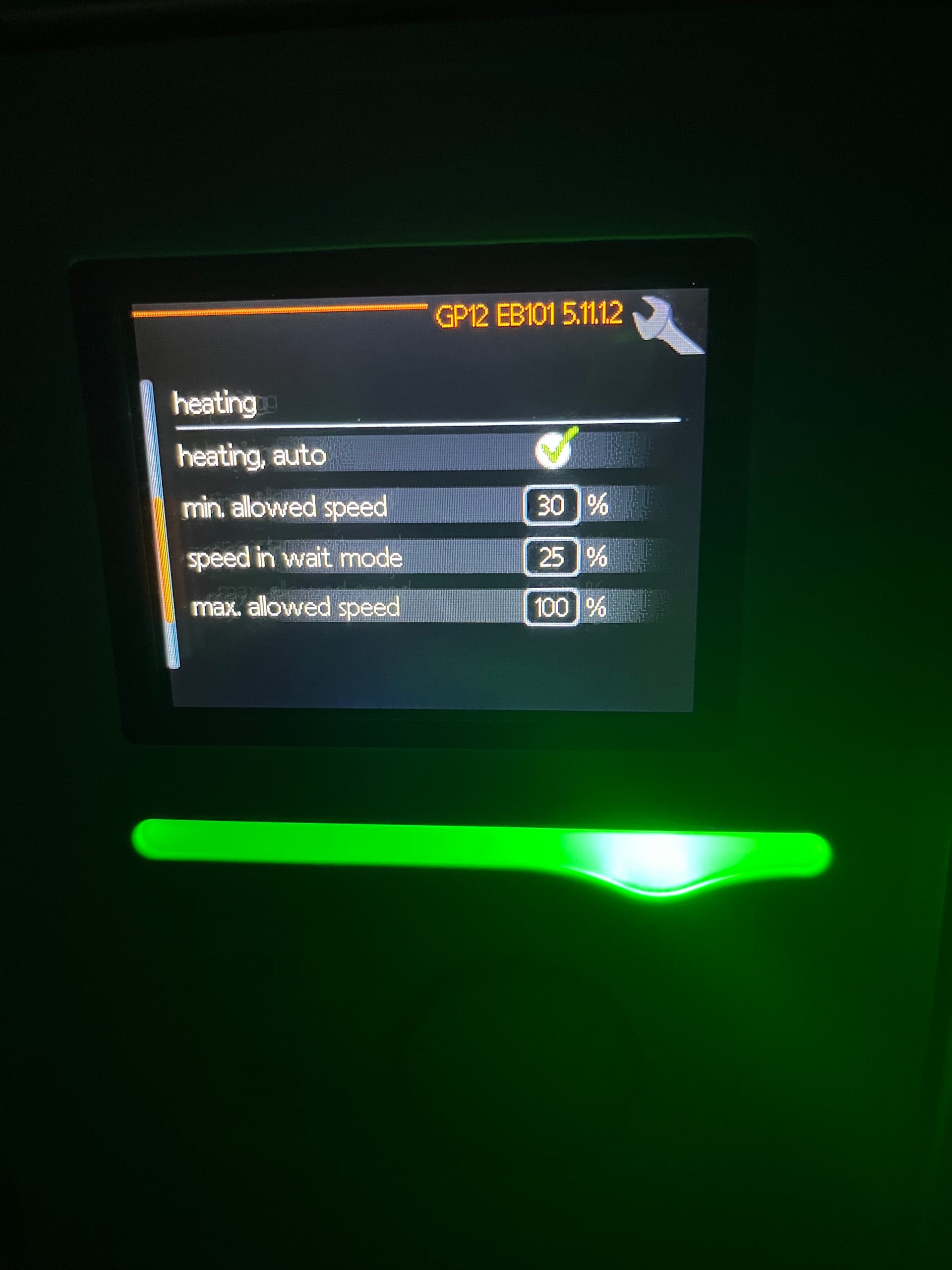
Do other NIBE users have experience of trying to control the Charge Pump Speed? Our unit often runs at low % values like 15%. There is a setting to adjust the minimum Charge Pump Speed%. I am tempted to adjust the minimum to 20% or 25% but somewhat unsure if that would make much difference in practice.
My understanding is that on NIBE systems, the Charge Pump Speed is controlled indirectly by specifying a deltaT value which the system then tries to achieve.
I exchanged some comments with John Cantor following the Eco Home Lab session when Trystan introduced HeatpumpMonitor, after I noted my system was showing the highest deltaT on the list (6.4 IIRC) and John advised increasing the Charge Pump Speed to try to reduce it. I was set on a deltaT of 7 degrees which I lowered to 4 and I observe the Charge Pump now runs at 90% rather than 75% (and deltaT is indeed lower).
Ours is kind of at the other end of the spectrum. So it often has very low Circulation Speeds at the low Compressor Frequency end of the operating range this often results in low thermal power output when I am pretty sure the more output (and higher COPs) are possible if the Circ pump speed was running a bit higher. Ideally it would be possible to apply some sort of scale factor to the Circ Pump Speed rather than only having indirect control as per your example.
OK so I have increased the minimum Circulation Pump Speed to 20% and it seems to be having a positive effect - I will try to report in a few days as the current cold snap is a reasonable test of this new setting adjustment.
Sorry for the lack of replies. I have my hands full here, but it has worked to our advantage as I’ve been able to observe my ASHP performance during colder temps here in the South of Scotland.
Since moving BT25 to capture the temp of the flow and the feed from the buffer I would say the ASHP has been performing a little better above 3 degrees outdoor temp. I don’t think I have yet maximised the deltaT which spends a lot of time at 2 - 3, until recently when it has been very cold, but not 5.
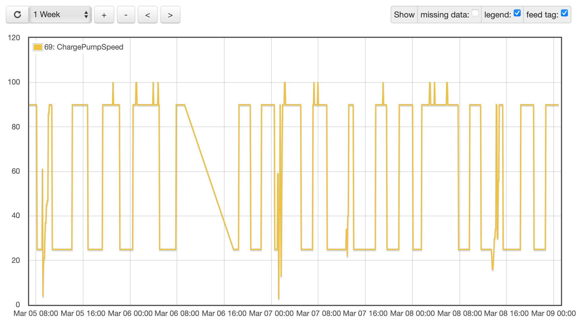
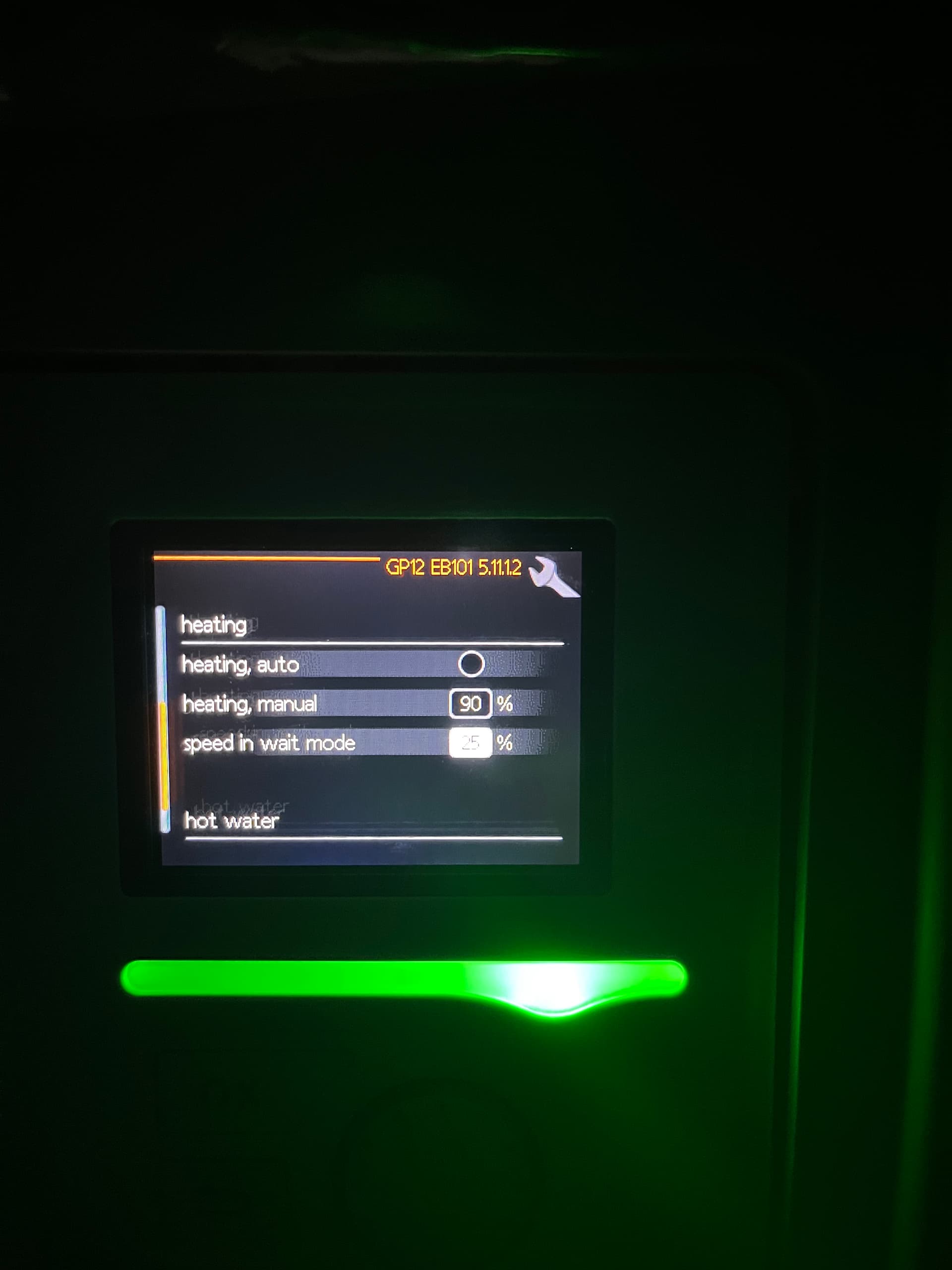
Charge pump speed doesn’t appear to be particularly dynamic. These are the settings I have just now and I’d welcome some thoughts on which way to tweak these:
If your buffer and pumps are set correctly and the correct stratification is achieved then the there should be very little temperature difference in the flow in and out of the buffer and the return to and from the buffer. So if you want a dT of 5 degrees then it should be obtainable across the system.
Well… the deltaT has come down (now showing 4.5 rather than 6.5 in the dashboard) and consequently so has the Flow Temp (average “when running” is now 36) so that’s all good.
What I’m not seeing is any improvement in CoP - which has actually got worse - but that’s confounded by a couple of other variables:
One issue with a Ground Source system is that the ground gradually cools down over winter and just now the ‘brine’ is coming in from the ground loops at 6.3 degrees, whereas it was more like 10 degrees at the start of December, That has the same impact on CoP as for an air temperature change of that magnitude with an ASHP.
In the warmer weather we’ve had for the past few weeks, my system has been spending more time on standby which is pulling about 60W for zero heat output (and about 20W of that is the Charge Pump). That makes the CoP look bad - but the running costs are excellent.
I’m #2 in the daily cost rankings (and winning hands-down in £ per m^2)
I could get a better CoP by shifting more heat, but then I’d be paying more…
Indeed. I’d assumed you’d reverted to “heating, auto” = On but if that’s Off then it’s just using the 90% when the compressor is running and the 25% when it’s not - hence the ‘square wave’ on the Charge Pump Speed graph.
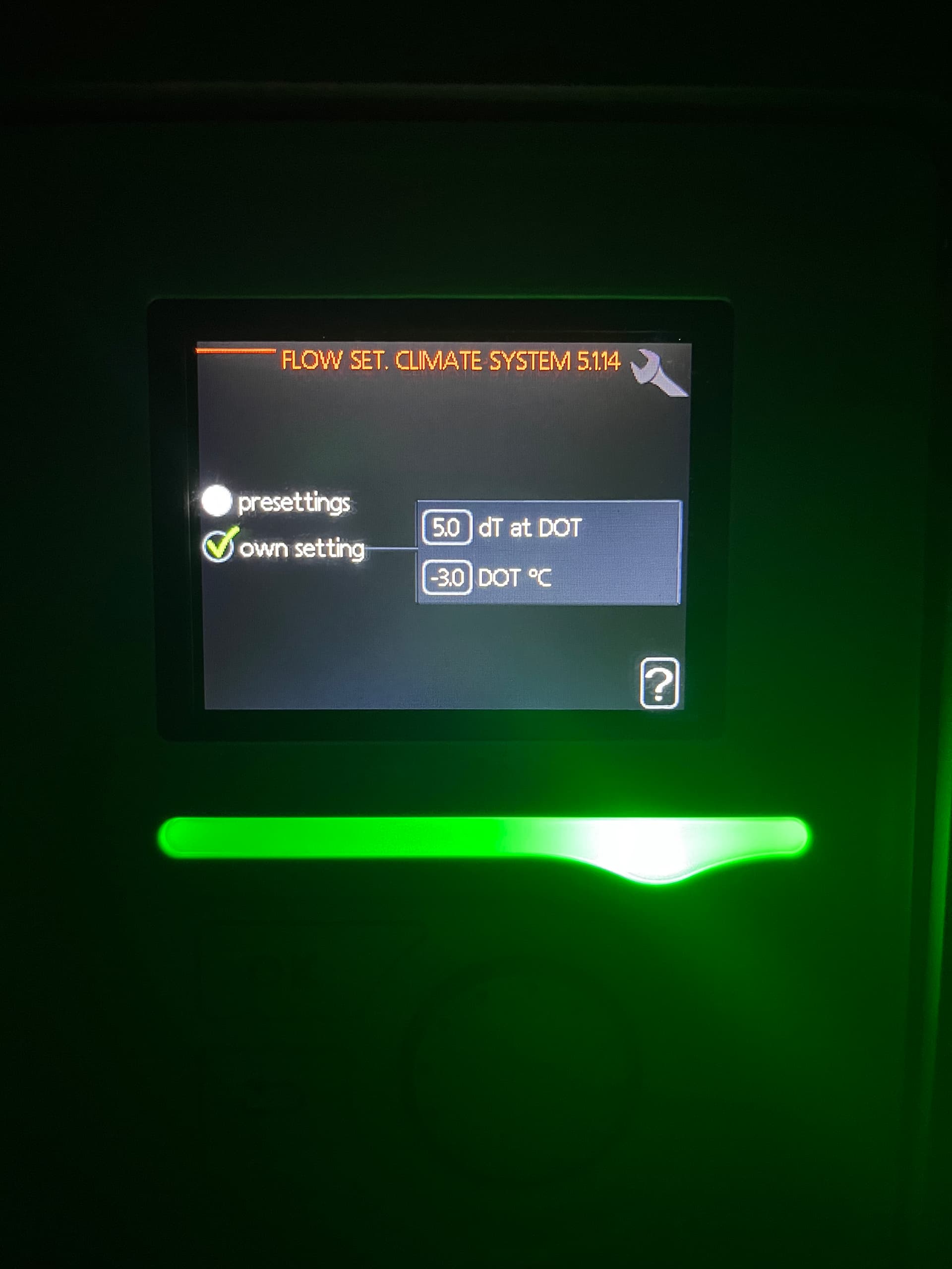
Yep. That’s rather cryptic but it’s telling the heat pump to adjust the Charge Pump speed to aim for 5 degrees dT (at the Dimensioned Outdoor Temperature, which is a measure of the nominal design condition).
A lower dT will tend to raise the pump speed (more water through the heat exchanger to cool it quicker) - but clearly it will max-out at 100%,
I don’t get how Nick is ever going to set his pumps correctly though Mike. If I understand his system properly, he’s got:
One pump running the Radiator circuit, with its own thermostat and zone valve
A second pump running the UFH circuit
If both those pumps are running, it will be hard for the Charge Pump to move enough water through the heat pump to satisfy them both - and if the Radiator pump is turning on and off (without the Heat Pump controller being aware) that’s surely going to mess up any attempt at pump speed balancing, isn’t it?
It’s never going to be perfection but more of a balancing act, so if we forget about temperatures at the moment and think more of flow rates, if the flow rate from the heat pump is 20ltrs then the flow rate to the zones needs to be 20ltrs but if the radiator circuit pump is running faster and demanding 25ltrs that will pull cooler water up from the bottom of the buffer lowering the temperature of the radiator circuit. The same applies to the ufh and this why good stratification is vital when using a buffer. If we look at temperatures you want to try and match flow in and out and return in and out and the only way is by adjusting pump speed
OK, but if the UFH pump wants to move 15 litres and the Radiator pump wants to move 10 litres - but the Radiator pump is switching on-and-off then what does Nick try to match with the Charge Pump speed: 15? 25? 20 as as halfway house?
I just can’t understand how a big, 2-pipe Buffer Tank piped as a ‘short circuit’ between Flow and Return is the right choice for Nick’s installation, whereas I can understand how a smaller, 4-pipe Buffer Tank would isolate the multiple pumped circuits from each other - something like the black tank shown in this other thread (which appears not to need it, since it only has a single emitter circuit).
Yes you are right a 2 pipe buffer will only add volume to the system whereas a 4 port will give some hydronic separation to the two zones. I am not over familiar with the ecodan so unless all of the pumps on the system are modulating pumps and all wired in to the control center to be controlled by the sensors, then the heatpump will see 1 circuit between that and the buffer and the other two circuits rads and ufh have to be controlled manually.
Don’t bother ever adding a volumiser to a system just use a bypass on the radiator furthest away from the heatpump, it’s only there to help defrost cycle.
Nick: I can’t see how you’ll properly fix this without some plumbing changes. You don’t need the additional Volume that is added by the existing 2-pipe Buffer Tank whereas you would benefit from the ‘separation’ or ‘isolation’ that a 4-pipe Buffer Tank (or Low Loss Header) would provide, letting each of the pumps work (more or less) independently.
I’m still curious how the original installer thought this was going to work, but if they’re not engaging with you then it’s probably better to look elsewhere.
Quick update! The installers finally agreed to send a plumber around who took one look and told me the cold return should not be plumbed to the UKV and it would need changing! Work is underway to make this happen. I’m sure he said it should be the hot water return instead feeding the UKV but didn’t mention a 4 pipe buffer at all.
Will chase this up once we’ve confirmed the work is going ahead.
ASHP performing well, Delta-T still pitiful though. The biggest gain for me by far (so far) has been modifying the DMS value.
That’s great news that you’ve got them to agree there’s something wrong with how it was originally plumbed.
When you get a bit further with planning the changes, the key question from me is what happens when the multiple pumps on the heating circuit are moving more (or less) water than the heat pump’s charge pump is producing.
I’ve not digested this thread fully but I have a NIBE system similar to yours so I feel your pain as there is not a large resource of community information.
Its been four years but each year has been a learning experience to optimise the ASHP performance. This heating season I plan to get the data into OpenEnergyMonitor although we don’t have a heat meter.
The biggest issue I found on our system was the compressor was cycling too frequently and the flow temperature varied wildly around the calculated setpoint. First I thought it was to do with the degree minutes but no change I made resulted in what I was looking for. The solution I finally found last October was to manually cap the maximum frequency of the compressor inverter based on the outside air temperature. In short I set it to it’s lowest unless it’s sub zero outside. At the coldest point this year it almost ran all day and the house temperature was fine. It’s possible to also limit it for HWS but I’ve left that max freq in auto for quick recovery.
Welcome to the forum. I agree that NIBE systems are much less common than some of the other brands but they do natively report a lot of operational parameters and once you setup some way to access those values and include them on a dashboard there are a fair few of us on here who’d be happy to take a look at the data and what that implies for how your system is behaving.
Nick has been very good at posting photos of his installation on this thread to help others understand his slightly unusual combination of pipes and pumps. I’d recommend you start a separate thread if you’re planning to post information about your own installation.