11.2kW monobloc R32 Ecodan showing COP2?

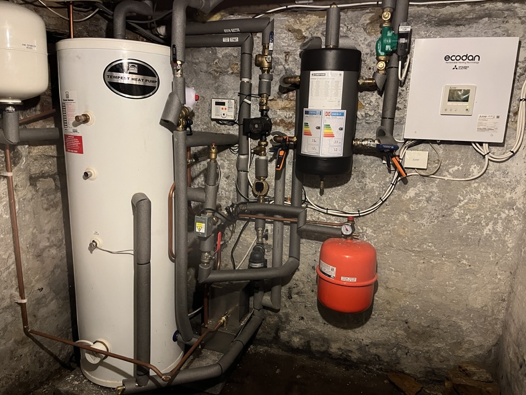
Friend asked me to come round and look at their 11.2kW R32 Ecodan.
Heat loss for house is 9.9kW at -3C outside.

So the good news
House is warm (20C), lots of big K2 rads
It’s long running, hours at a time
DT is showing around 5 when running.
unit is using weather comp with flow at around 40C at 6C outside

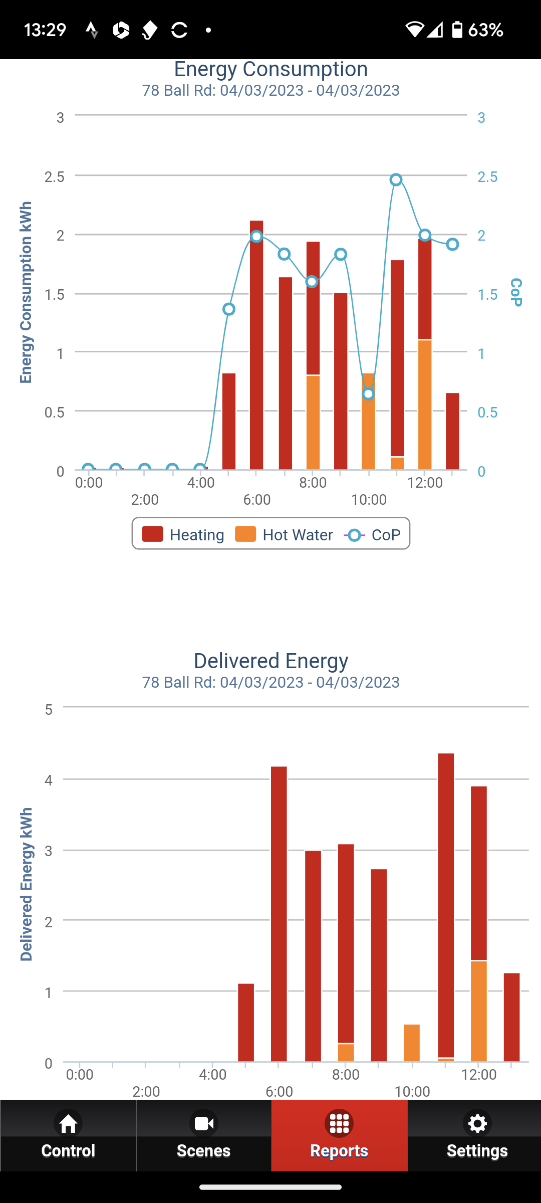
It’s mainly open system/rads but with a weird 12L 4 port buffer.
Although the flow/return seems to be okay across that.
I’m not sure what that is adding? Might be better to think about designing it out?

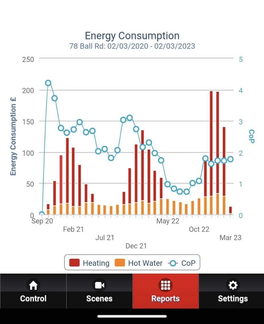
Electrical input seems reasonable for a house this size; 41kWh for first 3 days of March (around 5C outside)

But despite all this, the melcloud app is showing COP2

There does looks to be some undersized pipework issues; 22mm plastic on the ground floor and upto the first floor. They’ve put in a secondary pump on the other side of buffer. Assuming to give the system more umph to combat the 22mm plastic?

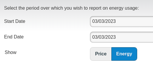
For March the LCD display it’s showing electric used as 41kWh and heat out at 74kWh. So 1.8 COP?
So the query really is, where is mel cloud pulling the info from? and is it accurate?
Are there heat/elec meters in the Ecodan getting this data?

There’s a Sontex superstatic 449 installed as part of MMSP, but doesn’t appear to be connected to anything online. So just serves as historical record. I can’t seem to see how to show ‘instant kW output’ from this old Sontex. Can you?

Could we get this old Sontex hooked up to emoncms?
There is a electric meter, but it’s not SDM, so we’d probably need a CT clamp.

All in all, it’s a perplexing setup.
Elec in looks ok, long run times, DT5, house is warm, reasonable flows… but COP says otherwise?

Can any of you Ecodan owners help us with this one?

1 Like

Hi Mick,

I can help with one bit - that “weird 12L 4 port buffer” is surely a Low Loss Header:

I’ve got an LLH on my system. They’re used when it’s desirable to ‘hydraulically separate’ the heat emitter circuits from the heat pump circuit, with separate circulation pumps on each side of the LLH - because the LLH is deliberately designed to stop any flow “pumping through” it. The customary use case is when there are two or more emitter circuits, each with their own circulation pump (often controlled separately) and where you don’t want those to mess with the flow through the heat pump itself.

1 Like

Are the sensors attached to the pipe work or in sockets from the 449?, if they are then you can scroll down through the menu to the power reading and although not bang on the button will be close to the cop you are actually achieving. I used to do this before I purchased all my kit from here to go with my 449 meter. Just had a quick look at mine and emoncms is reporting a cop of 3.18 and the heat meter is reading 3.6. This at least will give you an insight if there is a massive difference between Mel cloud and the heat meter. I would try and get accurate information first before changing anything on your system.

1 Like

Absolutely agree Mike, this is what i’ve told my friend.
We need to get all the info we can before deciding on a course of action. :+1:

And part of that is ensuring what we are seeing now is accurate.

2 Likes

Thanks David

I’d only ever seen photos of shiny coloured LLH before. I didn’t realise you can get them this big, or looking like buffer tanks. Learn something every day about heating! :smiley:

You’re right about pumps either side. There’s a main pump on the return (heat pump side) and then a secondary pump the other side of the buffer/llh heading to the heating circuit.

The heating circuit is just one big rad circuit. All open, with TRV (but set high/open).
Which makes me wonder why they have the LLH/buffer… unless the main pump hasn’t got the power to push through the small bore pipe? So need the secondary pump to help?

And my next question, how do you work out how what flow rates you need on either side of the buffer/LLH? :man_shrugging:

1 Like

I’m gonna post this here, but there’s long story of original installer going bust, MCS getting involved, different installer coming and doing ‘remedial work’ and the outdoor unit being replaced just a few months ago.

All in all, seems like a usual MCS approved installer mess. :angry:

1 Like

Hi there,

I thought I’d respond (owner of the system) - sensors are attached to the pipework (on the primary flow / primary return) - cable tied and then under insulation.

Ill see what I can get to from the menu’s and report back - may need a pointer to the menu layout if I get stuck!

4 Likes

I also have an 11 kW EcoDan, so I’ll add what I know about my system.

The EcoDan has it’s own temperature and flow sensors, so is theoretically able to estimate the COP based on those readings. They won’t have been calibrated though. It would be worth tracing where those sensors have been connected to the plumbing, and double-check they’re in the correct location. [see this thread]

I’d have expected the Sontex to have been wired into the EcoDan, so that Melcloud would report real, calibrate heat measurements. Assuming it’s been correctly configured that is.

There should be an electric meter somewhere nearby too, installed at the same time, also wired in. What are the kWh readings from both meters? That will give you another COP to compare. Possibly worth taking weekly readings for a while…

This sounds like it’s running well, except for the COP.

Looking at the MelCloud chart, the COP is way lower during the second year compared to the first. Something has changed with their system such that it is performing worse now. Have they had it serviced recently? Also note that the COP in the summer when only heating water is particularly poor, suggesting there’s an issue on the heatpump side rather than the heating side. The electric usage for hot water has also risen over the 2 years, so assuming that household consumption is the same, it is taking more energy to heat that water.

3 Likes

Also, what flow temperatures are being reported? The Hourly Temperatures report could be enlightening.

Tip: If you view the Energy Report for the last month, you’ll see bars for each day. If you select the same start/end date then you’ll see energy per hour.

image

We found both the ecodan and sontex temp probes. They are cable tied to the copper pipework, but nothing more. We could look at refitting those with some thermal paste/cable tie/kitchen foil etc as per @johncantor recommendation

2 Likes

I’m hoping most of the volume of that black ‘tank’ in the photo is insulation covering the actual LLH pipework.

Quite. If it’s just one emitter circuit then some concern about pump spec / capacity seems most likely. It would be good to understand the installer’s rationale for specifying a LLH in this scenario.

1 Like

For heat meter use, the sensors must be in a pocket. heat (Kw) is proportional to dt, so if the dt drops to say 3, then small sensor errors make a big difference. I need to look though my old notes… they are quite old now. For general flow/return sensing. strap-on should be good enough.

2 Likes

I’ve attached an example of the flow and return temperatures, and delivered and consumed energy as reported in Melcloud.

Let me know if these where not what you meant.


2 Likes

To my mind, this provides a bit of a buffer to stop the HP short cycling. If something reduces the flow through the heating circuit while the HP is running, the buffer will fill up with heat until the DT drops too low and it stops. The Heating circuit can continue to run gradually draining the Buffer until the DT drops again and the HP kicks in.

Yep.

Significantly reduces the accuracy.

Someone mentioned that they needed to clean the filters regularly and it did make a difference to performance.

1 Like

It would be nice to see a graph of the temperatures of the 4 sensors on the buffer/LLH. This would give an idea if its passing healthily, or if there is unwanted ‘dilution’

re heat readings. Someone should attempt to calibrate the Mitsi sensors (after strapping on VERY well) and see how this affects the heat readings. I assume it will… Simply running the circ pump with HP stopped and seeing if the flow & return temperures come together would help (being mindful of potential pipe losses) Sadly, Mitsi don’t display decimal points (what were they thinking?!) so not sure how to calibrate them.

1 Like

The unit has been serviced yearly and the filter regularly checked. Last time it was serviced there were no issues as far as I recall. (Thanks for the suggestion though!)

3 Likes

Yes John, I need to work out the most cost effective way to get all this into emoncms for Kev.

Based on the stats i’ve seen, I think the pump speeds look like this.

So why is the primary side running at 1260 for a 6 metre round trip in 28mm copper, but the secondary side, battling with 22mm plastic and 3 floors to cover is only 1100?

I’ll be honest, I don’t understand the relationship between the primary/secondary side and how you decide the pumps speeds etc.

Yes, these are what I mean. Studying these charts may help you understand what the heat pump is doing. Also look at tank temperatures during hot water cycle.

I’m particularly curious about what’s happening around 10am when is only heating water, and the COP is less than one! How is the hot water configured? How big is the cylinder?

It is possible to scrape data directly from Melcloud into Emoncms without any additional hardware; that’s what I do (with apologies to OEM guys). There’s a python library somewhere on GitHub, a couple integrations for HomeAssistant, or can write your own.

3 Likes

It’s a 200l Telford tempest cylinder - definitely a heat pump cylinder (I queried this before). Apologies - when you say how is it configured - do you mean physically i.e pipe runs or are you meaning actual settings on the heat pump/ftc5 controller?