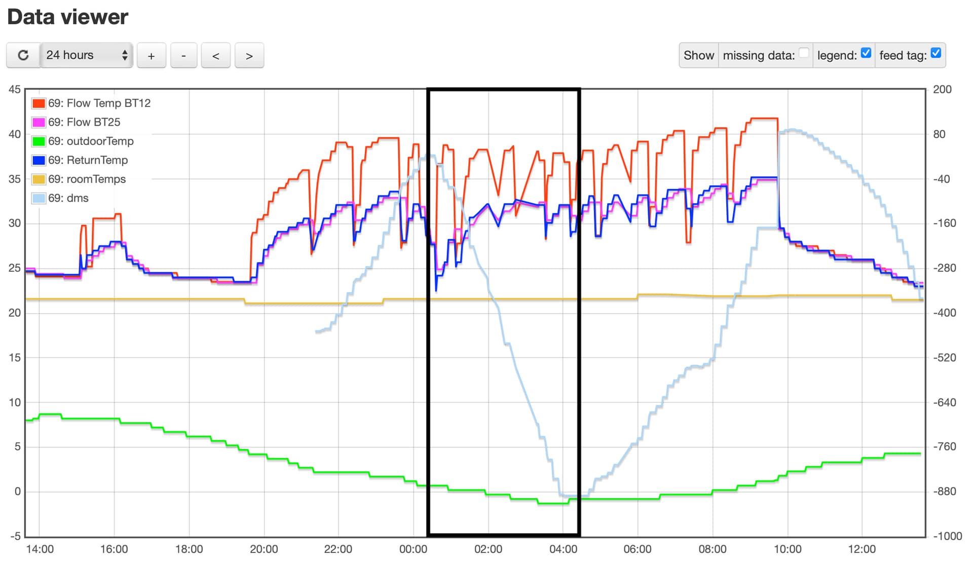
The Degree Minutes are going more-negative and yet Flow Temp (BT12) is generally about 5 degrees hotter than Return Temp (presumably BT3), so I’d expect the DMs to be increasing.
Sorry Nick - I must seem like the never-satisfied data monster ; would you be able to include S1 ‘Calculated Flow Temp’ on the graph too please? That will show what flow temp the Weather Compensation thinks it needs to deliver to match the heat loss, based on your selected WC ‘Curve’.
(The DM value is calculated from the difference between the Target flow temp and the Actual flow temp.)
Hello Nick,
For information I have just measured the flow and return temps of my Samsung 16kW unit, which supplies 5 manifolds and 18 U/F zones:-
Flow - 40 degrees
Return - 34 degrees
Hello Nick,
I have just read a higher post.
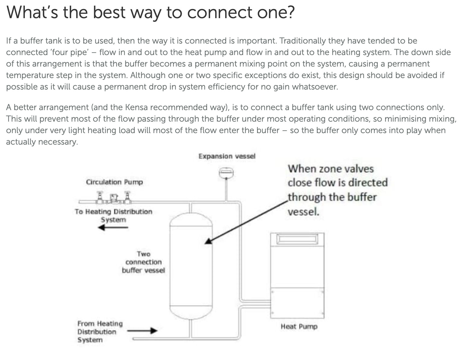
I have only just installed my ASHP and was aware of the issue mixing in the buffer causing a temperature step change. I connected my flow pipe directly to the input of the circ pump and added a T to connect flow direct to the the buffer flow connection and the buffer flow outlet was then connected via another T back to the circ pump inlet. The aim was the circ pump to be fed directly from the ASHP and minimise the amount of flow from the mixed water from the buffer tank. This was only partly successful as I have a 2 degree temperature step, caused by the buffer vessel. But obviously this may have been a lot higher if the piping described above hadn’t been fitted. I have however fitted valves that will allow me to force all the flow through the buffer vessel and my aim will be to then measure the temperature step and the return temperature back to the ASHP to determine the full impact of the buffer vessel.
If this information is useful to you please let me know?
RJK
It’s good to know there’s options then should this definitely be required.
The rads and UFH are designed to run at 45, according to the installer’s docs but really struggle to get much above 30 and I think this is due to the reasons above.
You know, there are some times when I look at the temps and wonder why it’s heating when target temps seem satisfied and no stats are calling for heat… There’s something going on here for sure.
I’ve got S1 coming in to EmonCMS from this evening, I’ll post a further update tomorrow.
I’ve also posted my design to the HeatGeeks Facebook page to see if they can shed any light.
I’ve a neighbour with the same install, but not the same problem who says he did have some remedial work carried out and will find out more about that tomorrow too!
Maybe; a reducing DM value means the Actual flow temp is lower than the Target flow temp, which I see on my system when the compressor is Off (but you’re seeing it when the compressor is On, which is odd). It will be good to see the S1 graph to compare - I’d expect a sudden step-up in S1 when your scheduled higher room temp kicks in.
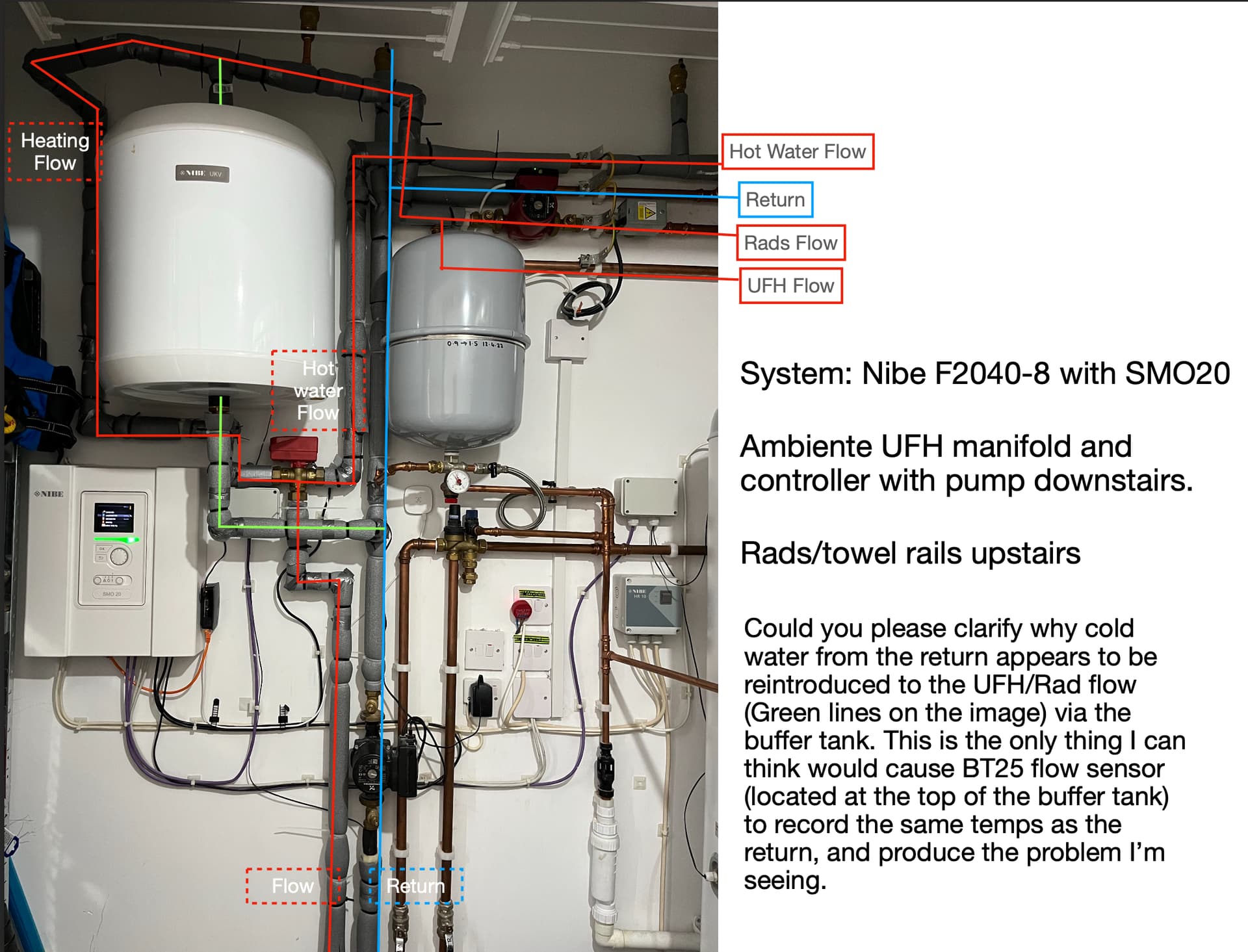
I’m now questioning my earlier assumption, quoted above, about BT25 (not) being an important feed into the Weather Compensation algorithm.
We know BT25 is reporting dodgy readings (and we think that’s because it’s seeing ‘Return’ water rather than ‘Flow’ water, coming up via the Buffer Tank) but if the controller is relying on those readings as an indicator of Flow Temp, for its Weather Compensation logic, that’s not good and would give unpredictable results - and the data is definitely showing some of those.
I now think that’s worth a try. Apologies for steering you away from it when you originally suggested it.
There are pros and cons of putting it to the left or the right of the Tee above the Buffer Tank; on balance I’d say put it to the right, so it measures what the UFH and Radiators are actually getting (and we can compare it to BT12).
I think BT25 is important. As our findings have developed it’s clear to me the problem is the temperature of the water leaving the buffer tank and cooling the flow destined for UFH and Rads. Ultimately, this stops the heating circuit being able to achieve any temps much above 30.
I did think about moving the sensor, but that would not change the fact that the water is being cooled when it shouldn’t be. And, I’ve just finished re-insulating the piping there and taping all the seams… Although it looks like it’s becoming more obvious that some sort of re-piping is necessary.
There are some settings available in the engineer menu to alter the resting speed of the charge pump, and I’m thinking of tweaking those to see if it can draw more of the cooler return out of the system and to the ashp rather than back through the buffer. As we saw in an earlier chart, the charge pump isn’t doing very much at all, which could be the root of the problem (other than design).
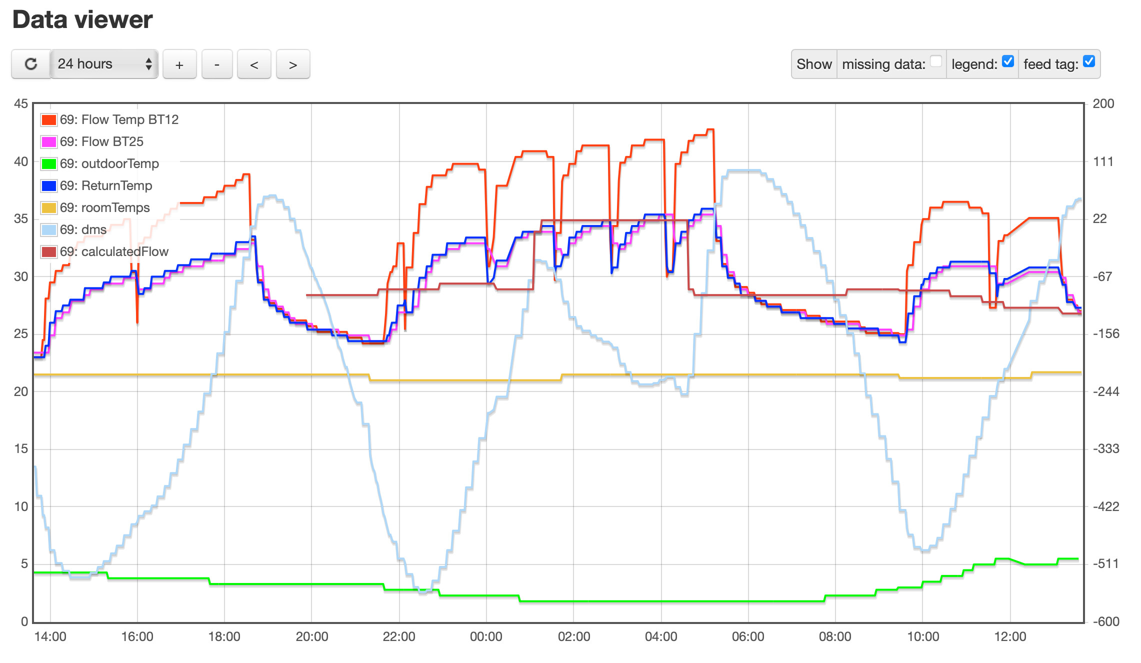
Here comes the science bit…
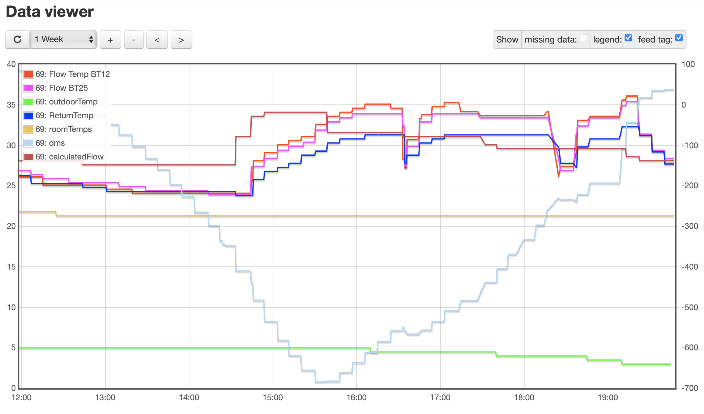
Added Calculated Flow Temp, which shows the jump at 0030 - 0430 for off peak and smaller changes based on the outdoor temperature.
BT25 flow continues to follow BT3 return.
BT12 flow increases and DMS is doing stuff I still don’t fully understand:
Thanks Nick. I completely agree that moving the BT25 sensor isn’t going to fix the underlying issue with the plumbing layout and the relative speeds of the different pumps.
That new graph including S1 (Calculated Flow temp) is extremely helpful in inferring how BT25 is being used. (The data monster is finally satisfied! )
As background, here’s my understanding of NIBE’s “Degree Minutes” parameter:
The Weather Compensation (WC) algorithm Calculates a Flow Temperature ‘Target’ (S1) which it predicts will offset the heat loss of the house, based on the Outdoor Temperature, the requested Indoor Temperature and the selected WC ‘Curve’ (for those not familiar with this term, it’s basically just a way of saying: at Outdoor Temperature X deliver Target Flow Temperature Y)
It’s rare for the Actual flow temp to match the Calculated Target flow temp, so the ‘Degree Minutes’ variable keeps track of the extent to which the Actual flow temp has been Above (positive) or Below (negative) the Target - by how many Degrees and for how many Minutes
Think of this as a ‘credit’ or ‘debit’ balance for the heat delivered to the house
Overall, the control algorithm aims for a DM value of zero
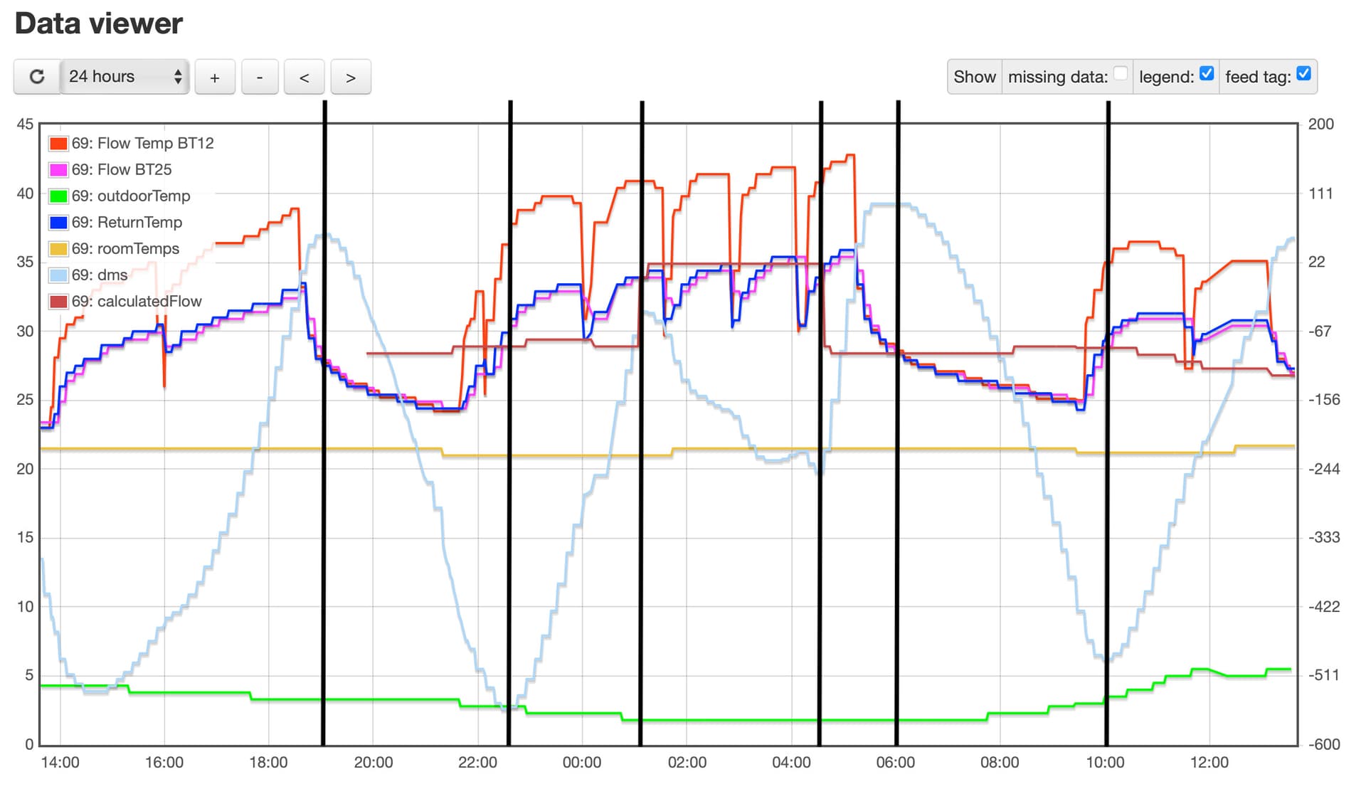
We can see from your latest graph that the DM value (pale blue line) changes from a negative slope to a positive slope when the BT25 (External Flow Temp) line crosses the S1 (Target Flow Temp) line. I’ve marked those crossing points with black vertical lines:
This is important because it appears to confirm it’s BT25 (and not BT12 as I’d previously believed) that is being used to asses ‘Flow Temp’ for the WC algorithm - which in turn appears to explain why you’re seeing erratic behaviour, since on your system BT25 is not reflecting the real Flow Temp.
Indeed; I tweaked those on my own system recently to decrease the ‘idle’ speed and to increase the ‘compressor on’ speed (by lowering the target DeltaT). By default, the Charge Pump speed is controlled automatically to deliver the target DeltaT - but if the DeltaT is based on BT25 that will be all over the place (which might in turn explain the crazy-looking charge pump speed graph you posted previously).
In the short term, you might be best off swapping to manual control of the Charge Pump speed using the Service Menu. I’m getting a pump speed of 90% in Heating mode, 50% in Hot Water mode and 30% in Wait mode, so maybe try something like that.
By forcing the Charge Pump to a high speed, there will be less of a tendency for the other pumps to ‘over run’ it and hence less of a tendency for water to flow the wrong way through the Buffer Tank.
Again, hugely helpful. I think we are on the same page. I’ve seen slightly different options available to me in the Service Menu, but have increased the speeds, albeit not as much as you. I will see if it makes much difference tonight, so far though, no change.
But BT25 is accurate, it’s the temperature of the water that is the problem, no?
Yep; agreed. We’re both getting a much better sense of what’s going on with your system.
For the avoidance of doubt, I’m running on ‘auto’ for the pump speeds and the 90% / 50% are what I observe via NIBE Uplink when the heat pump is aiming for the DeltaT I specified (5 degrees).
Well, BT25 is accurately measuring the temperature of the water it’s seeing - but we’re fairly sure that’s the Return water coming up through the Buffer Tank.
Your radiators are actually getting something slightly warmer than BT25, since they get a mixture of the flow from the Heat Pump (BT12) and the Return past BT25.
(That’s still colder than you want in the rads though - and the heat pump’s delivering water at more than 40 degrees so not especially efficient).
In summary, I reckon there are two issues:
The way the plumbing has been configured, with the combination of the Radiator and the UFH pumps pulling the Flow water faster than it’s being supplied (leading to some of the Return water being mixed in)
I can’t see anything except some re-plumbing fixing this
The fact that BT25 is giving a misleading reading - far too close to the Return temperature (thus upsetting the DeltaT calculation feeding the automatic speed setting for the Charge Pump) and lower than the actual Flow temperature (so messing with the Degree Minutes calculations).
This might even be bad enough to cause the controller to think the compressor can’t supply enough heat, causing it to switch in resistive electrical heaters (if you have those on your system)
Hi all
There seems to be a lot of over thinking going on and relying on sensors telling us whats going on, Going back to basics will help solve some of the issues here. your buffer tank should supply you heating circuits alone with a feed in from your heatpump a feed out to your circuits at the top of your buffer and return from your heating circuit and return to your heatpump at the bottom. This is were correct stratisfication will occur and the return flow will not mix with the feed flow if your pump speeds are correct and you will have the correct deltaT. if your pump speeds are wrong you will be pulling return flow up through the buffer back into the flow circuit causing a tempreature loss.
Your cylinder should be fed direct from your heatpump and never go through the buffer. There seems to be a lot of over complicating you system when the basics should be
1 a diverter valve to switch between hot water and heating
2 2 zone valves to turn on/off rads or underfloor linked to thermostats for zones
3 a mixing valve on the ufh so you can run higher tempreatures on your system without damaging your flooring.
it doesn’t matter what readings you are getting because until the system is correct the readings are meaningless.
This is not a slur on anyone but you will chase this forever and not achieve anything and i see it everyday in customers homes where they are complaining about under performing heatpumps
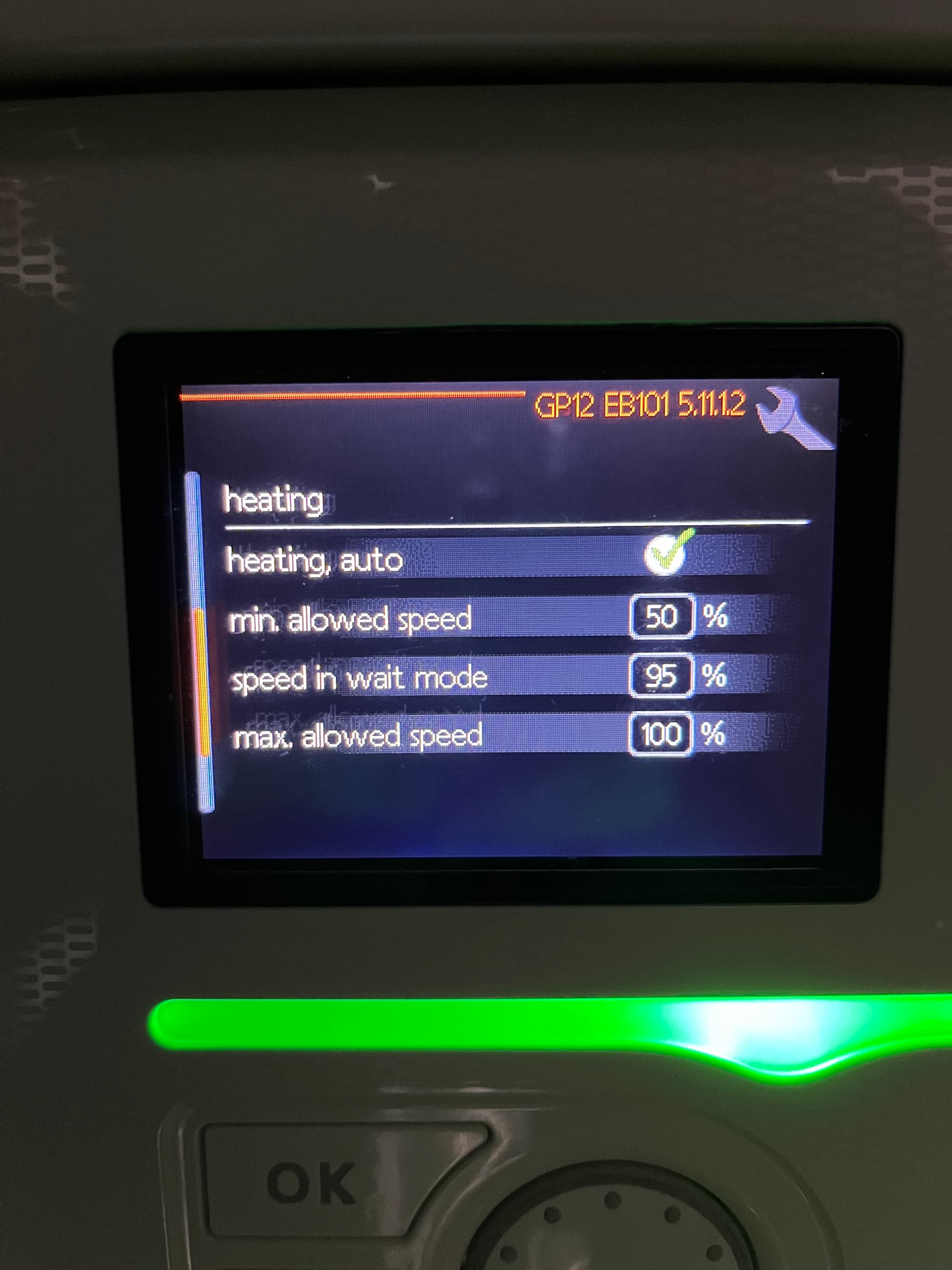
OK, so changing the charge pump speeds definitely had some effect, although I’m not completely sure whether it’s a good effect or not. Firstly, these are the settings I have access to with the latest firmware for SMO20:
If I untick ‘heating,auto’ then I can set the speed when heating, but not explored this yet.
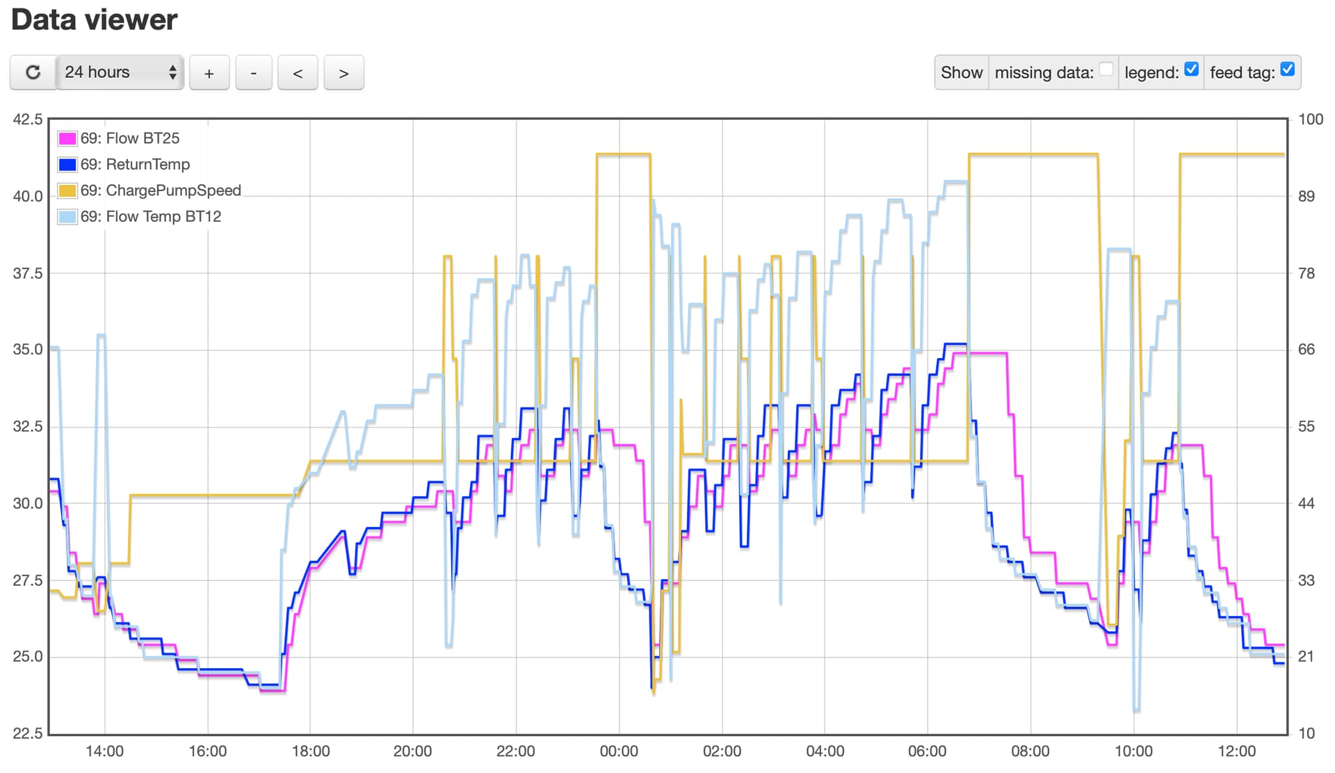
With these settings I am seeing some interesting results:
When the charge pump is running at 95% I’m seeing more like what I would expect to see for BT25 vs BT3, but BT12 looks like it is now following BT3, I guess all the cooler returned water is heading to the ASHP, which makes sense:
For the majority of the time though, the charge pump isn’t running fast enough to maintain the deltaT between BT25 and BT3.
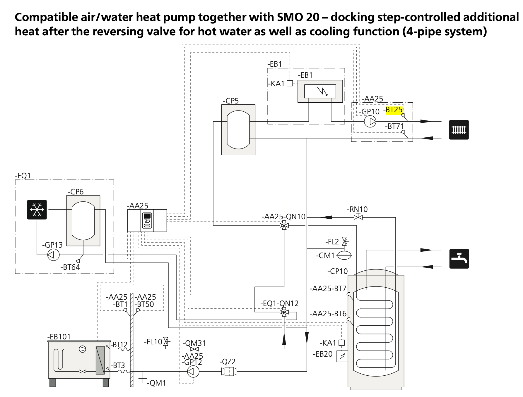
Returning to the placement of BT25 sensor. I thought I had read somewhere that BT25 should be placed at the top of the buffer thank, however after checking the SMO20 manual I can see that BT25 is placed after the pump for the heating circuit, which probably would make a difference.
Further to this, some research in to plumbing in buffer tanks suggested the plumbing is correct, although the buffer should only be in use when heating zones are closed, which is almost never here…
So, I plan to relocate BT25 to where the manual says it should be, reset the charge pump to the settings it was before and monitor the system for another 24hours.
I’ve asked for a HeatGeek plumber to come and have a look at re plumbing and waiting to hear back from the installers on their logic.
Yes, I think that’s what is happening, although reducing the rads / ufh pumps and increasing the charge pump doesn’t seem to have fixed the issue. Can you advise on how I might determine the best speeds for the pumps?
BT25 is behaving much more line BT12 and only following BT3 when not actively heating! Result!
I’m going to monitor the system for the next few days and then re-assess where my efficiency journey should take me next; I suspect meddling with the charge pump speeds and DM compressor start value…
Looks like BT25 is holding pretty close to BT12 too, so not much evidence of the colder return water diluting the flow.
For the record, where exactly is BT25 now? Is it on the Radiator leg of the flow circuit or upstream of the branch to the UFH, so it will register flow from both Radiators and UFH?
Hello Nick,
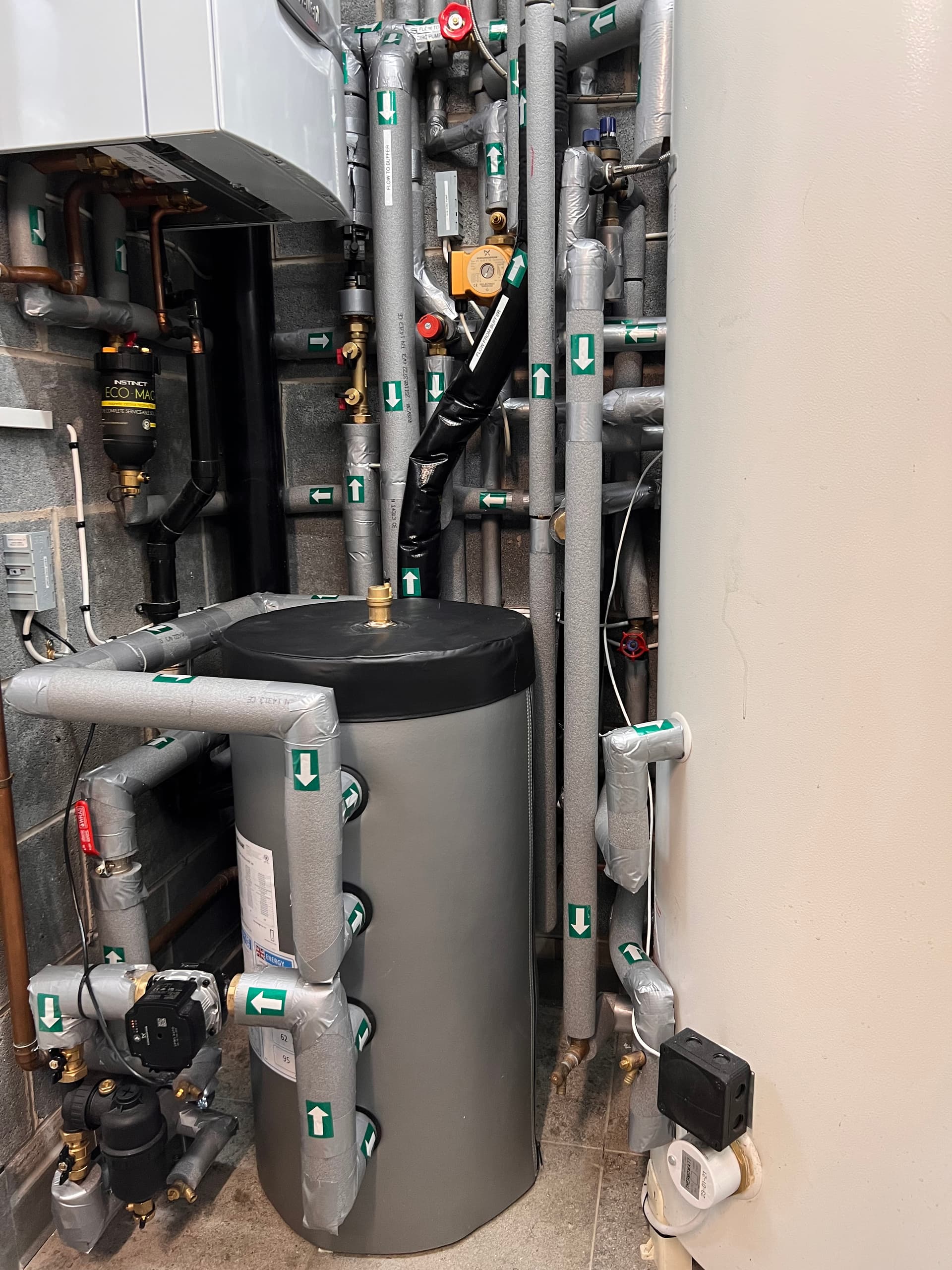
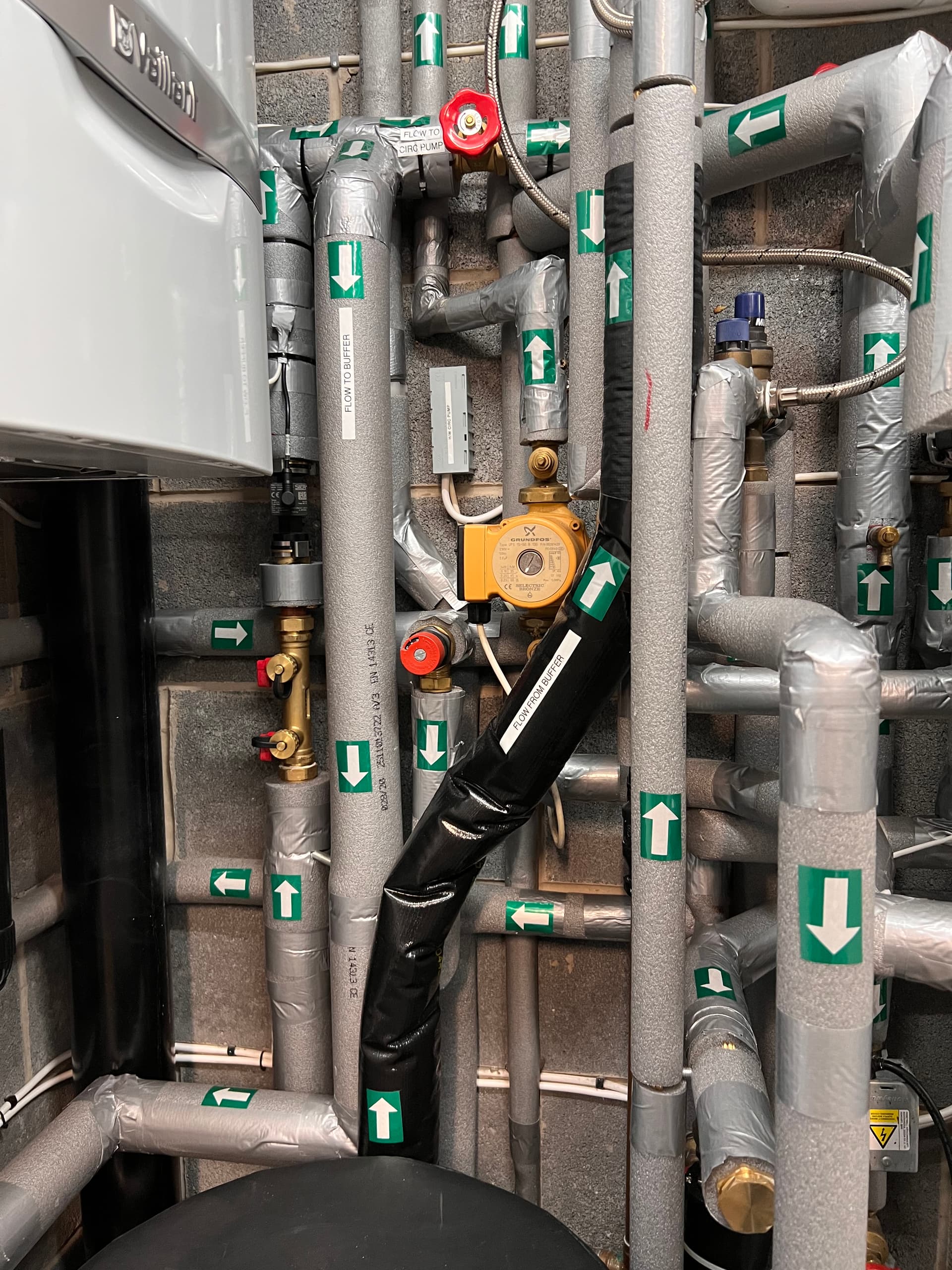
Please find attached photo’s of my installation, I commissioned mine last Friday and for 2 days the unit ran flat out until all the concrete floors came up to temperature. From that point onwards the unit has modulated the output from 1.2kW to 2.4kW (electric). Overall everything seems very stable and no excessive cycling. The CoP is the same as Glyn Hudsons Samsung unit. For the first couple of days the flow to return showed a difference of up to 6 degrees, but when the house came up to temperature this has slowly reduced. My initial conclusion after a few days of use is the temperature step is probably acceptable and when the unit is running at very low output the temperature step caused by the buffer is very small. I also used the Kenda idea, but as the vessel had 2 inputs and 2 outputs, I used all of these to keep the fluid entry velocity as low as possible.
The following photo’s show how it was piped.