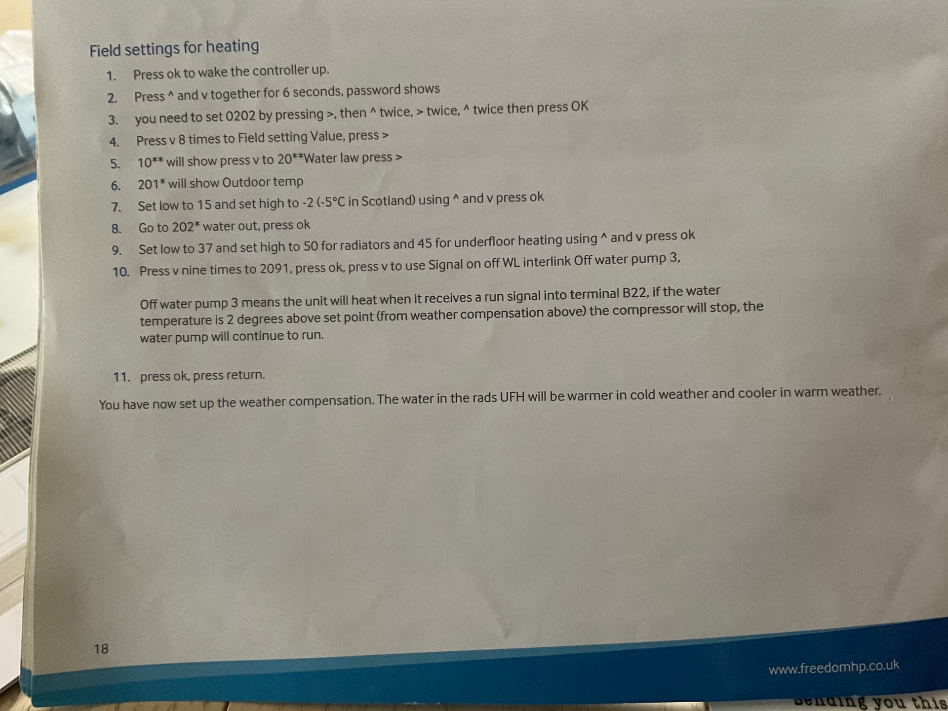
The below image is from the Freedom Heat Pumps installation manual for AE050/080/120/160RXYDEG.
Hi Christian,
Again, a revelation. Many thanks.
The Graph shown is excellent …and triggered thought.
My “unique” system has a 50 litre “Volumising Tank” fitted across the Primary ports of a Plate Heat Exchanger.
The Heat pump, when supplying heat to the Radiators has a Water Volume of 56 Litres.
The Heat when supplying the Hot Water tank has a Water Volume of 6 Litres.
Therefore, the Time constant , or Cycle time , of the Heat Pump, is nine times longer when supplying the Radiators than the Cycle Time when supplying Hot Water.
The Hot Water supply Cycle time will be nine times shorter than the Space Heating Cycle Time.
With the Volumising tank fitted across the Primary of the Heat exchanger
Energy Consumed = Flow T x Sp_HT x Volume = 35 x 4.3 x 50 = 7525 Joules = 7.525 KJ.
With the Volumising tank fitted across Heat Pump
Energy Consumed = Flow T x Sp_HT x Volume = 50 x 4.3 x 50 = 10750 Joules = 10.75 KJ.
Therefore the Volumising tank was fitted across the Primary of the Heat Exchanger.
The Hot Water will therefore oscillate with a 9 times higher frequency than the Radiator Feed.
QED
ian
Thanks Ian and @christian!
Is the heat exchanger used instead of a coil in the hot water tank? or is it between the heat pump and the radiators? any chance you could draw a diagram of how it’s connected up?
Technically yes, but if considering the thermal mass of the operating mode [while heating the water] you will need to consider the water tank + heat exchanger interaction with the 6 litre volume of pipe. [I am assuming when heating the hot water, the heat exchanger is used, and when not it is direct to the radiators]
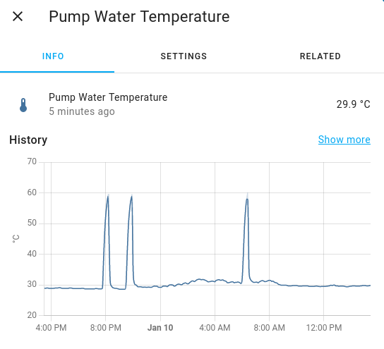
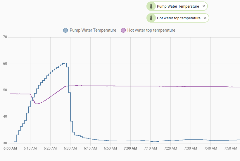
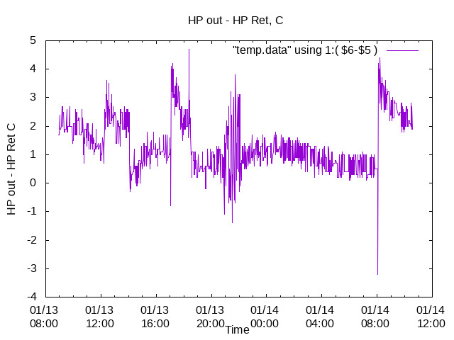
For reference here is my flow temp data (pump is on the flow), the spikes are when heating the hot water tank (I have a different setup to yours of course as I have re-used my existing 300l copper vented tank - with some modifications to make it a bit like a mixergy tank)
my main observation is that my flow gets back to normal very quickly, and does not jump around as much as yours, though there are many differences between how I am measuring and how you are measuring. In anycase you may find this useful.
Hi Trystan and William.
Again many thanks.
Please see the attached drawing , of a by now, very complex Heat Pump.
Samsung-inchinnan.pdf (20.1 KB)
William , again you are technically correct, in that Thermal load of the Hot Water Tank should be added to the 6 litre pipe volume. My Comment was only intended to show the differences between the Radiator Cycle Time Constant and the Hot Water Cycling Time Constant.
My Water Cycling oscillations only occur when heating Hot Water.
My Power Cycling oscillations only occur during De-icing.
The Heat Exchanger was fitted in order “to isolate the Heat Pump from Variations in Flow rate and pressure on the radiator circuit”.
The Volumiser tank was fitted “to reduce the cycling experienced when the Heat Pump was delivering at it’s minimum output , 25% , of the Maximum Output Power” during Sept/Oct 2022.
A later statement from Dalliam Samsung required the Volumiser tank for frost damage prevention.
Both of my manufacturers , Samsung and Telford, required the Volumiser tank to be fitted.
The Calculations of the Volumiser volume are shown in the MCS “Domestic Heat Pumps , A best practice Guide” page 35 under “Buffer Vessels”.
Using the " MCS Best Practice " I calculated the required Volumiser tank Capacity as 35 Litres.
Samsung Dalliam were going to "install the Volumising tank and issue a Warranty certificate , but at an further large cost of circa £5000.
A 50L Volumising tank was installed in late October by my “installer”.
The MCS "best Practice Manual " page 35 has issued a Warning.
WARNING from MCS.
“Buffer Vessels can perform important functions if incorporated correctly, However they can also increase system heat loss.”
The Hot water tank can climb to 50 C where the Energy stored would be
Energy loss in Volumiser if fitted across HP out and HP return
Energy ( Joules ) = 50 x 4.3 x 50 = 10.75 KJ
Energy loss in Volumiser if fitted across the Heat Exchanger Primary ports
Energy loss ( Joules ) = 35 X 4.3 x 50 = 7.725 KJ.
The loss being least when the Volumiser was fitted across the Heat Exchanger.
ian
HI William,
Again , many thanks for the data from your Heat Pump.
The Differences between your Temperature Measurements and my own , are vividly contrasted.
My Temperature Measurements are the Temperatures as measured on the outside of the pipe, while yours are presumably taken inside the water flow itself.
My Temperature measurements are also taken using K type Sensors , which are both extremely fast and extremely sensitive to Electrical Noise.
I will have to get your , in pipe sensors asap!
I have been pondering the question " at what temperature should a Backup Gas heater be activated ?".
My Electricity costs 33.763 p per Kwh .
My Gas would cost 10.276 p per Kwh.
The Electricity to Gas Ratio is therefore E/G = 33.763/10.276 = 3.28.
The Temperature at which the Heat Pump COP = E/G would set the point at which the Gas Backup should be started.
Looking at the COP to Temperature charts
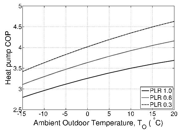
Note that my PLR , (Power Loss Ratio ) = Operating Power / Maximum Power = 2Kw/5Kw = 0.4.
I would conclude that the Gas boiler should start when the temperature goes below -5 C.
As an aside, I have noted the YouTube video describing the 201 - 203 * Field settings containing the comment
" The default settings, 201-203 are Expensive and should be modified to -3 C and +13 to +17 C depending upon the House insulation.
The user " should, however, experiment to find a suitable balance between Room Temperature and Economy".
The Video announcer then says
**Users in Scotland should use -5 C and +13 to +17 C , but experiment **
Again many thanks for your help
ian
Hi William,
I am now content that I understand the cause of both the Hot Water cycling and the Energy Pulsing.
I can explain , and justify, everything, except the Water Temperatures, with the Water Temperatures requiring a proper, immersion sensor array.
I can explain All , but can do nothing!
I have asked the three other “installers” who originally quoted for the job for their opinions.
All three have asked for varying sums of money to “repair, and or replace”, the Heat Pump, with the largest , taking £96 for their “advice”. Another wants to , not only replace the Heat Pump, but also the Pipes and the Radiators! While the final contender has launched a personal attack on me , blaming me for my “stupidity in selecting” such a parcel of rogues.
Were it not for the intervention of my MSP I would be in serious financial trouble as well as cold!
I should have , like yourself, built the Heat Pump myself!
I will , however, build a proper Temperature measuring array for the Water Temperatures on the Heat Pump.
ian
HI Trystan,William and Christian,
Why is Energy measured in Kwh ?
Energy in the Gas industry is measured in MJ/m^3 ,Mega-joules per Cubic meter.
Power is measured in Kw , Kill-Watts in all industries.
The printed characters Kw is very similar to the printed characters for Kwh.
The Confusion would be stopped if All industries, including the Renewable industry, measured Energy, ,unambiguously, in Mega-Joules , MJ
MJ looks completely different to Kwh.
Kwh looks too similar to Kw.
Conversion
1 kwh = 1000 J/sec over 1 hour = 1000 X 60 X 60 Joules. = 3.6 MJ.
Why NOT use MJ for Energy!
Use Kw FOR Power !
ian
How is Lord Kelvin involved? K is the symbol for degrees Kelvin. And what about James Watt - isn’t he deserving to be honoured by a capital letter?
My guess is, as a Chartered Electrical Engineer, is it’s down to history, and kW & kWh are far more convenient for us, as they don’t involve multiplying and dividing by a pesky 3.6 or 3600 every time we measure a current and a voltage. OK, a joule is one watt-second, but an inconveniently small unit for most purposes.
Hi Robert,
The Joule
Such a heat unit, if found acceptable, might with great propriety, I think, be called the Joule, after the man who has done so much to develop the dynamical theory of heat… Siemens.
I was hoping you would respond!
I appreciate the history of James Watt , William Thomson ( Lord Kelvin ) and James Joule.
However, the use of the Watt , the Kelvin, and the Joule should be open for debate.
I am not proposing the Joule as a measurement of Energy …
I am proposing the Mega- Joule , MJ
The “pesky” 3600 multiplier would be replaced with a multiplier of 3.6.
The MJ would emphasise the environmental cost of using too much energy.
A bill in Mega-Joules would be sure to frighten the punters!
ian
Thanks, It would be interesting to monitor the flow and return temperatures either side of the heat exchanger and before and after the volumiser. There is a fair bit of debate as to the benefits or drawbacks of installing low loss headers, buffers or heat exchangers, you might find this page and accompanied heat geek video interesting Low Loss Headers: The Complete Guide For Efficient Design, heat pump manufacturers usually specify hydraulic separation as a precaution as they dont always have control over what kind of heating emitter configuration is connected to the heat pump and so need to make sure that there is adequate flow at all times… regardless of how the user has set their TRV’s etc. It might be worth collecting more data on your system before passing too much judgement. It is possible to get systems with hydrolytic separation to work well, though my experience with the use of heat exchangers for this is limited…
I personally have a heat pump without one of these sources of hydraulic separation and instead ensure that there is always adequate flow and system volume by keeping all radiators in the house fully open at all times. Here’s the diagram of my system:
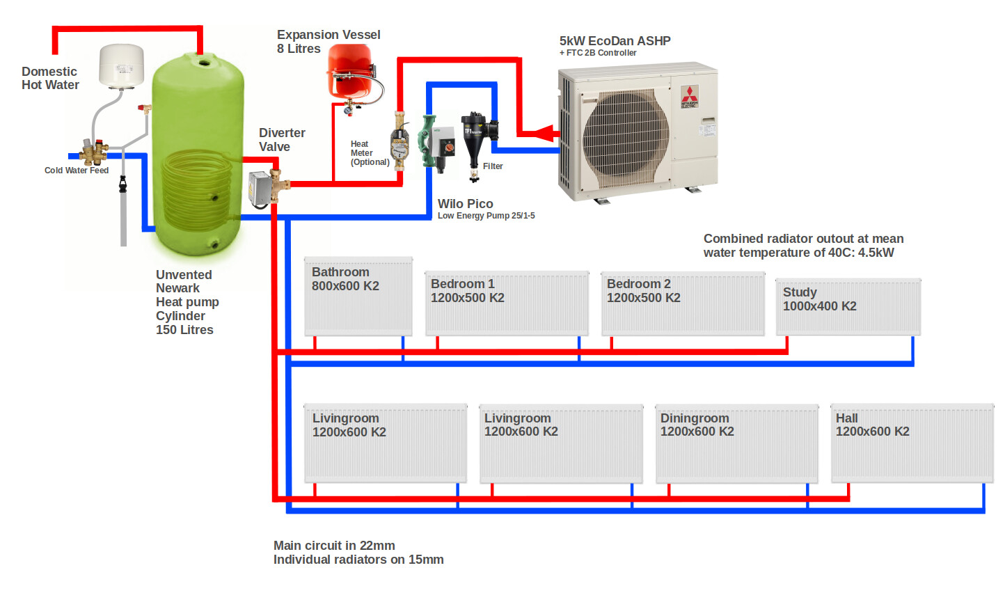
It has worked well for me now for 3 years and counting, providing a SCOP of 4.08, here’s the monitoring data dashboard Emoncms - app view dashboard. Glyn’s samsung installation is an identical configuration.
The COP required by the heat pump to break even is not quite that high, as the gas boiler is not 100% efficient. This study found that the mean efficiency for combi boilers in the trial was 82% https://assets.publishing.service.gov.uk/government/uploads/system/uploads/attachment_data/file/180950/In-situ_monitoring_of_condensing_boilers_final_report.pdf
That drops the break even COP required by the heat pump to 33.763÷(10.276÷0.82) = 2.7
That boiler efficiency does not as far as Im aware include the boiler electricity consumption, central heating pump and controls which are all usually included in the heat pump SCOP values.
I wish I could! ![]()
That’d keep my electrical bill to a minimum.
Hi Tystan,
Your System drawings are excellent , far better than my own!
My biggest problem has been the complete absence of documentation about the System design. Assuming there was any design in the first place!
Telford , the maker of the tank said that “the Heat Exchanger was indeed fitted to isolate the Heat Pump water Flow from the user operated TRV’s.”. This is the only explanation, or justification, I have received about the Heat Exchanger.
The very existence of the heat exchanger mystified my installer who continued to install a heat pump without a Heat Exchanger.
In not acknowledging the existence of the Heat Exchanger , my installer “forgot to fit” a water flow Sensor, Expansion vessel and PRVs.
The Water flow sensor, when discovered by myself in an unopened box , was fitted to the Output ports of the Heat Exchanger!
The water flow sensor was eventually moved three times before being declared faulty!.
Eventually , the Heat Pump was started, but the Heat Pump was relentlessly Cycling .
I asked the manufacturers , Samsung and Telford , for their opinion.
Both Samsung and Telford recommended that a 50 L Volumising tank be fitted.
In Late October , the Volumising tank was fitted by my “installer”.
The Cycling stopped when supplying the Radiators but was ( and is ) readily apparent when heating Hot Water.
All of this has taken some 7 months!
My installer , with his multiple failures , was refused MCS certification!.
Without MCS certification , I was refused my loan from the Scottish Government.
Eventually , my MSP intervened asking EST-Scotland to pay me the cost, so far, of the installation .
A Nightmare…!
I should have installed it myself!
ian
Hi Trystan,
My own introduction to Cycle smoothing is shown on page 35 of the excellent MCS “Best Practice Manual”.
Heat-Pump-Guide.pdf (1.2 MB)
I particularly like the examples in the MCS write up.
Following months of patronising indifference at the hands of the MCS, I am loath to give the MCS any praise, but,their best practice manual is excellent.
My Heat pump , having been installed in the teeth of an international Energy crisis on a particularly cold December, makes the attribution of “cause Difficult”.
Are my perceptions of high Electricity bills “caused” by the Large white clouds of Water Vapour covering my garden at night?
OR
Are my perceptions high Electricity bills “caused” by the innumerable Energy warnings displayed on the Heat Pump display?
ian
Are you able to quantify how far outside of your expectation the high electricity bills are? In the discussion above we worked out that the electricity consumption at least was in line or lower than the original installers estimate?
What is still unclear to me is if you are getting the quoted heat output for that electricity input. Your COP of 3.0 for end of december early january is a bit on the low side but at least is slightly less expensive than gas assuming a boiler efficiency of 82%, but that period misses the coldest temperatures experienced over the proceeding few weeks.
You mentioned using 10,740 kWh of gas in 2021 which at a boiler efficiency of 82% would give 8812 kWh of heat into the house. A heat pump with a COP of 3.0 would consume 2937 kWh of electric over the year to deliver the same amount of heat, adding an additional ~£980 to your electric bill at 33.4p/kWh.
The other important indicator at the end of the day is the temperature of your house and how that compares with comfort levels in earlier years with the gas boiler. How different are your internal temperature now compared with 2021?
@glyn.hudson mentioned seeing large white clouds of water vapour with his I think, and I’ve heard others say the same on other systems. I havent really noticed that on mine, but then my heat pump is out of sight at the back of the house and may defrost a little less vigorously
Do you have any pictures of those by any chance? any other samsung folk here have experience of that warning message?
If I had your system, in the absence of spending a lot more on montioring I would keep a record of the electricity consumption and energy generation figures as given on the samsung display, alongside a note of outside and internal temperatures.
Then using your thermocouples try to work out if there is much difference between the flow temperature from the heat pump and the flow temperature of the water going to your radiators, and then the same on the return side, how does the return temperature of the water from the radiators compare with the return temperature of the water going back to the heat pump. That will give an indication as to the impact of the heat exchanger and volumiser…
Does the heat exchanger have any identifying brand and model number info printed on it by any chance?
Hi Trystan,
Your contributions have been excellent , as usual!
I am *logically well aware of the savings of the Heat Pump compared to my former Gas boiler",
The Arithmetic and logic , is impeccable! The Heat Pump is more efficient than Gas!
I have repeatedly told myself that I am indeed saving money by using the Heat Pump.
But , I am faced with a December Bill, that , even with the Governments discounts, drives me simultaneously into fuel poverty and hypothermia.
Could I ask an explicit Question?
Given that my Samsung Heat Pump has a series of controls designed to limit Fuel consumption, should I use them".
For my Samsung these Power Limiting controls are selected using Field Parameters 5041, 5042 and
5043.
What type of controller should be attached to the CNS 046 Socket on my Control board to allow for Power Energy Limitation?
ian
Hi Trystan,
Again, Many thanks for your patience!
The Heat Exchanger was manufactured by EAC under the EEC directive, (remember them !)
PED 97/23.
I am little worried about the losses of the, very well insulated , Heat Exchanger used to heat my Kitchen.!
I have an unused kitchen Radiator with the Heat Pump piping , Hot Water Tank and Volumiser Tank “leaking heat” into the kitchen, with the Heat loss maintaining a steady 19 C Temperature.
I am considering reducing energy consumption by only heating the Kitchen!
The Heat loss in the Kitchen , does , however, currently reduce the heat energy available to the Living Room, my now , sole remaining heated room.
I am currently taking your advice , and, building temperature sensors for every room and the outside.
I currently record the Delta T across the Heat Pump Outputs( HP out -HP Return)
and
The Heat Exchanger Output - Heat Exchanger output Return in
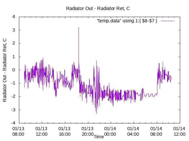
and
The Absolute HP output Temperature, HP out .
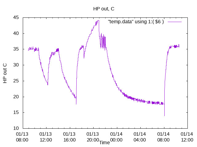
The Absolute HP Water Temperature is adjusted by the Water Law Thermostat to operate between 30 and 35 C, limiting Energy Consumption.
Knowing the flow rates on each side of the Heat Exchanger I could work out the Exchanger efficiency.
All of the Temperature readings are taken from the outside of the copper pipes using K type sensors.
All pipes are thermally connected, affecting the water temperature reading.
All Temperatures are noisy because of the use of , sensitive, K type sensors.
QED 1.I need some immersion Temperature Sensors.
QED 2. I need some immersion Flow sensors.
ian
.
I’ve recently had a Samsung installed so closely monitoring COP. One thing which has occurred to me is exactly what the Samsung definition of ‘Energy Generated’ my initial assumption was it would be Heat Output - Electical Input, so COP= (energy genareated + elec consumed)/elec consumed. But everyone else is working that energy generated = heat output. Does anyone have the definitive answer?