Hi Trystan,Christian,William, Glyn
A Question?
Should my Flow water Temperature ALWAYS be controlled by the Weather compensation Graph ?
** OR **
Should my Flow Water Temperature be controlled by the Weather compensation ONLY when the room Temperature is below the Room Thermostat demand Temperature.
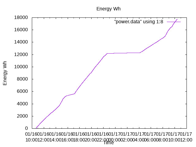
With the first option I am presented with numerous Electricity consumption warnings during cold weather!
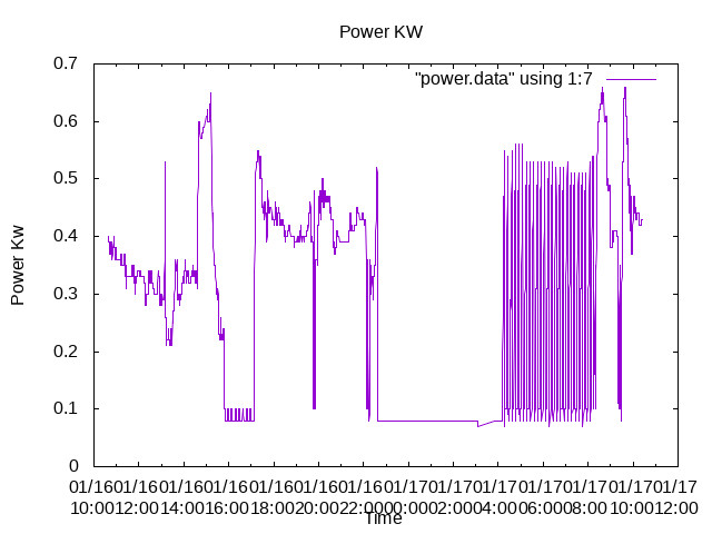
With the second option the Heat Pump remains OFF for long periods during the night.
Is this advisable?
To Samsung Heat Pump users
The First option is set by the default setting of Field Option 2093 selected with 2091 and 2092 NOT used.
The Second option is set when Field option 2091 is used with options 2,3 or 4.
Can anyone confirm that
Field options 2 , 3 and 4 select different values for the Weather compensation Thermostat Hysteresis .
Hysteresis being the difference between the Thermostat switching ON when the Flow Water Temperature is rising and switching OFF when the Flow Water Temperature is falling.
ian