I’m looking to take my heat pump monitoring a step further and have been playing with the MyHeatPump app.
My current set up involves feeds of data from emonTx4 (power only), MelCloud, and Octopus.
This gets me pretty close to everything I need to feed into the app. I’m hoping to be able to fill in the blanks - the most prominent of which is heat output.
I fully understand that this figure is not going to be 100% accurate due to MelCloud but want to get as close as I can without adding to the setup. *
MelCloud provides Flow and Return.
I know the flow rate to be 24l/min.
I have been looking at the calculations and believe this should get me to a power figure which I can accumulate to kWh.
Is this a reasonable approach?
Is processing the inputs the easiest way to achieve this? Or can I do anything with virtual feeds?
Do I need to take anything else into account? Pumps, OperationMode, etc?
I have been doing something similar to estimate heat from Melcloud for a handful of systems.
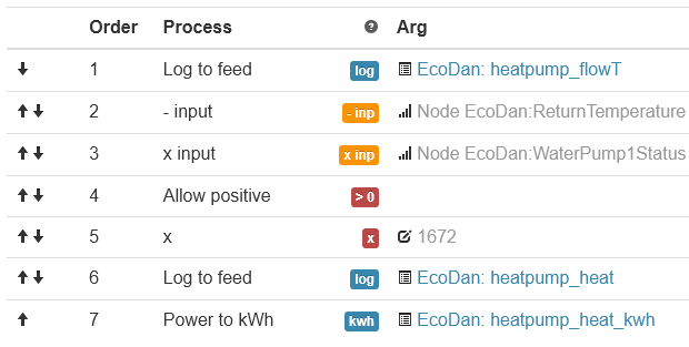
I’ve calculated the heat output for different flow rates. 24 l/min equates to 1672 W per K of dT, where dT is the difference between flow and return. If 20% glycol then this drops to 1572.
water: 4182 x flow rate / 60
glycol: 4000 x flow rate / 60
(If you’re able to read actual flow rate, use that instead)
The feeds you need to pull from MelCloud are:
FlowTemperature
ReturnTemperature
WaterPump1Status - primary pump
ValveStatus3Way - 0 = heating, 1 = dhw
Then use input processing to compute the following:
Hot water may have a different flow rate, but I’ve not tried to compensate for that. Difficult to fiddle with using input steps, but could be calculated separately and then combined.
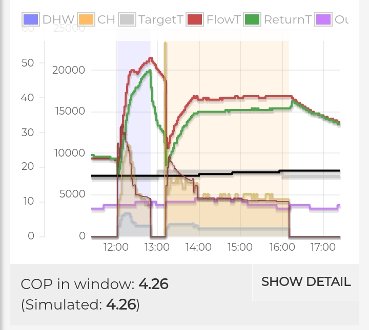
Yes, these will plot nicely in My Heatpump app.
Here an example compared against carnot factor 0.5:
When fitted with meters*, Melcloud reports watt-hours for the past minute. Multiply by 60 to get current power in watts.
*CanMeasureEnergyConsumed value will be true.
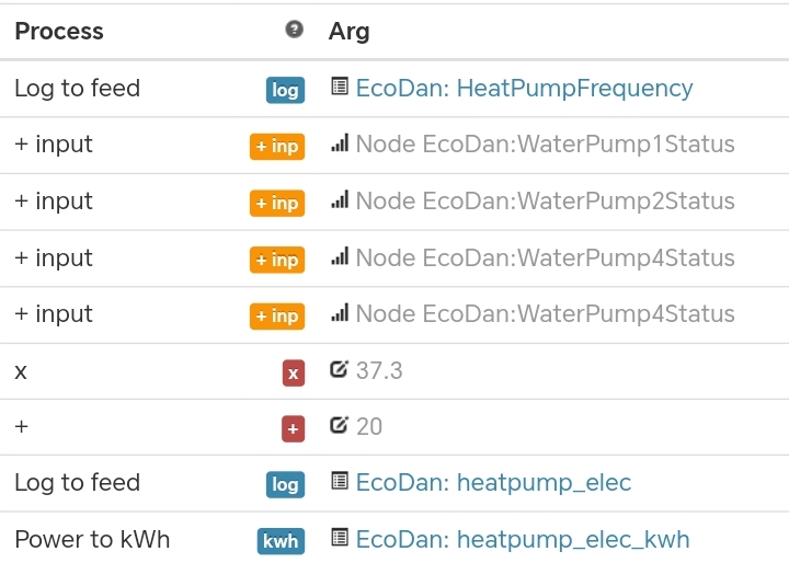
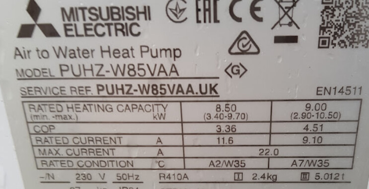
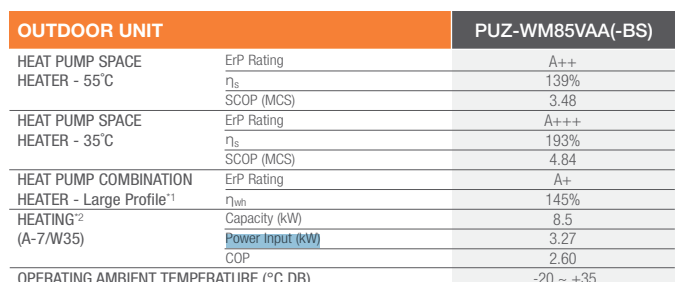
When there’s no meter, input power can be estimated using HeatPumpFrequency, which is compressor percentage Hz. Divide by 100 and multiply by the maximum electric input for that model in watts. I.e. 3,270 for 8.5 kW model, 3,730 for the 11.2 kW model. I also add in the pumps to give something a little more realistic, but it’s very crude. Oh, plus 20W for standby.
I dunno, maybe. For the systems I’ve looked at this happens to map to 100 Hz = full power, and matches the readings I get from my electric meter. Lucky coincidence I guess.
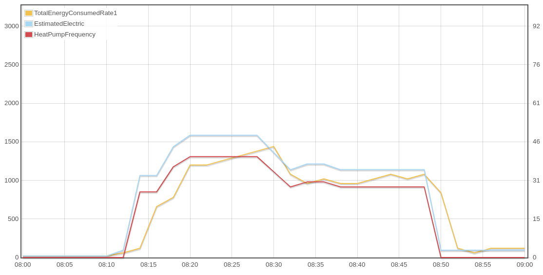
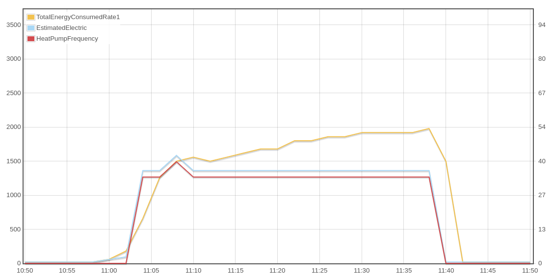
Measured vs. Estimated electricity on left-hand axis up to max input watts for my unit.
HeatPumpFrequency (red) on right-hand axis up to 100 Hz.
I have struggled to sensible numbers from larger units, so maybe they go higher than 100 Hz? So knowing that maximum would allow converting Hz to %. I’ll dig into the history for those units to see if there’s a correlation…
I don’t see why this would matter. This is just equates to less power use, right?
Umm… may need to add 15-25%? FTC claims 12 or 13 l/min for my system, yet calculating the flow from the measured heat & dT comes closer to 15. I presume because the Sika is not calibrated for glycol.
I’ve not tried reading the actual flow rate from the heat meter as it’s hard to get to.
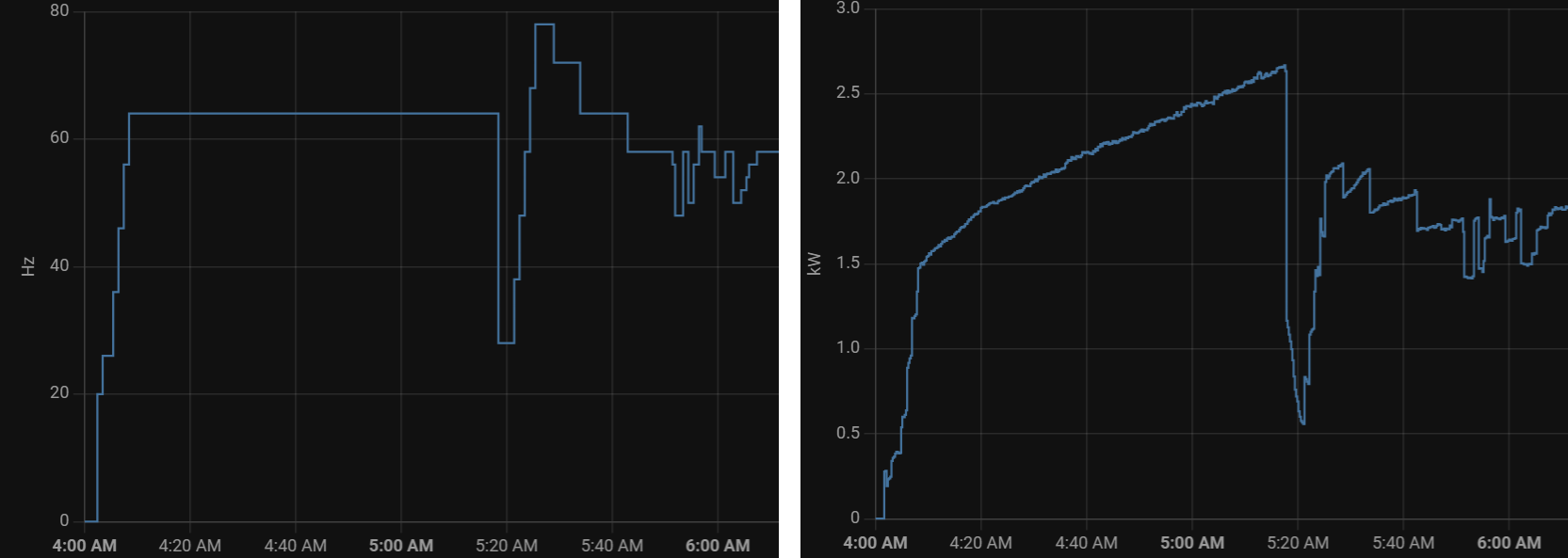
Yeah and this is where i would differ, frequency at Eco cap of 64Hz and consumption continues up to 2670W.
Then swap to heating, frequency up to 78Hz and input power down to ~2000W
I guess this is due to the compressor having to work harder as the refrigerant gets hotter, and so pulls more power for the same frequency. I see the same during the hot water cycle.
(34 Hz, not Eco, but Quiet Mode 1).
So, this estimation of electrical consumption isn’t great and will produce optimistic COP during DHW runs. Could maybe include an extra fiddle factor for flow temperature, I guess. It does seem to be good enough for diagnosing; a couple users have been able to improve performance of their systems based on this data.
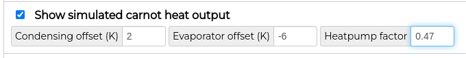
An alternative approach uses Carnot COP equation, which might work better where an electric meter is installed. Multiply measured electrical power by Carnot COP to get an estimate of heating power.
Can view this directly in the My Heatpump app, using a typical factor around 0.4 - 0.5. Useful for sanity checking the other estimation method.
Or calculate it programmatically. I use this for a Vaillant system that comes with MID approved electric meter, but doesn’t report flow rate or return temperature so can’t use mass flow equations:
Note the 100W threshold for ignoring standby + pump power; this may need to be higher for larger systems (also a setting in MyHP app). It would be more accurate to subtract the standby + pump power rather than cutting off at the threshold. Or have separate meters for compressor, pumps and controller.
Did you figure out a better formula for estimating power draw? I’m taking on a 5kW system to monitor remotely, and would like to get the numbers better if I can.
Well reports are that pretty good for 8.5kW, as expected it’s slightly over estimating for a 5kW and slightly under estimate for a 11 or 14kW. It’s reasonable enough to make big changes, but probably not to fine tune.
I’m not really sure how to compensate for the different sizes as there isn’t anything in the FTC to suggest the outdoor unit size without a user input…
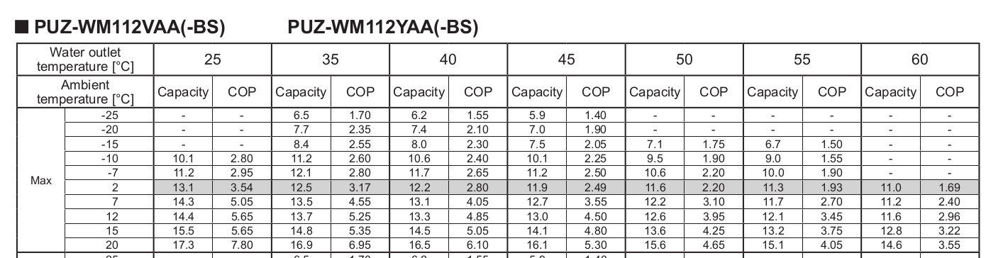
I’ve spent some time figuring out a better way for estimating how much power the heatpump draws. I started with the performance data from Ecodan_ATW_Databook_R32_Vol5.3_.pdf that shows the Max* Capacity and COP:
(*“Performance at Maximum compressor frequency”)
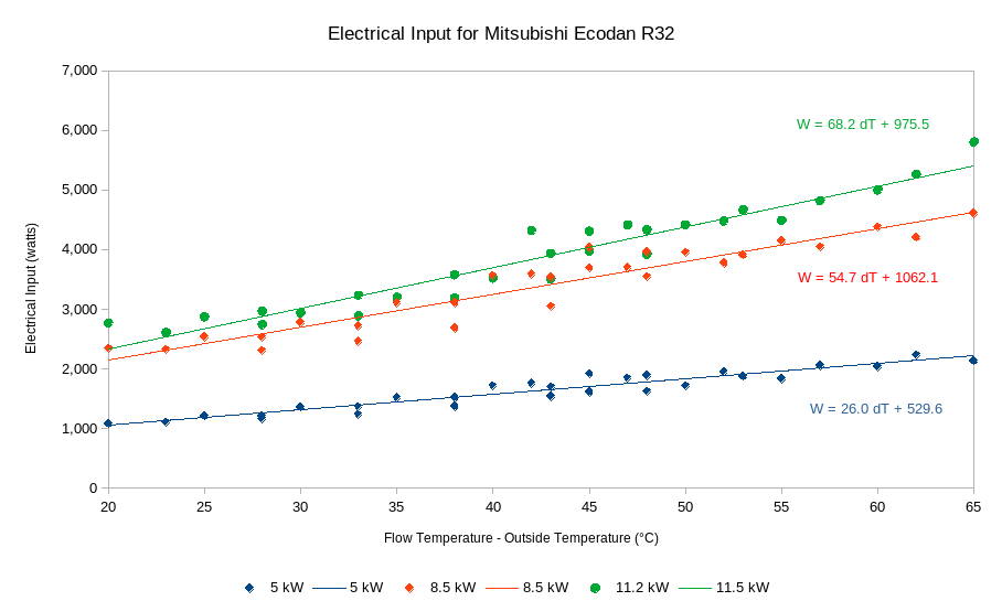
Capacity ÷ COP gives me the input power in kW. Plotted as watts against Flow Temp - Ambient Temp is very nearly linear. I ignored values below -10° and above 15° as these didn’t fit well and aren’t typical for UK climate. I also ignored 2° ambient as that includes defrosts, and omitted 25° flow.
The trend lines fit with R² of 0.9, and give us formulas for each of the three models I looked at:
(I did look at fitting a quadratic instead, but the end result wasn’t much different)
5 kW - 26 dT + 530
8.5 kW - 54.7 dT + 1062
11 kW - 68 dT + 976
From this I was able to work out the following formula implemented in a virtual feed:
Flow temp - Outside temp
× factor for model, e.g. 68
+ offset for model, e.g. 976
× HeatPumpFrequency ÷ maximum frequency¹
+ 250 W if compressor is running²
+ 100 W if primary pump is running³
+ 20 W for standby power
¹ max frequency possibly different for each model, I don’t know. 110 Hz for my system
² I guess this is for the big fan and other things going on when compressor is running
³ pump power probably depends on the speed setting…
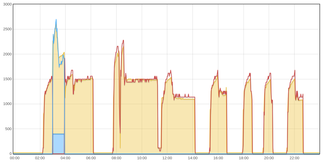
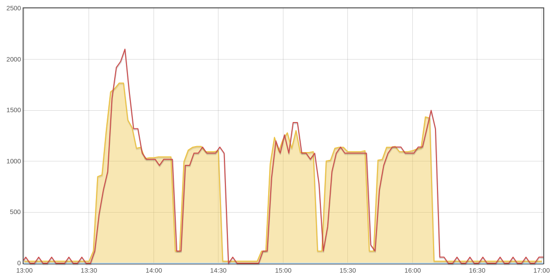
Here’s measured vs. estimated for my system on Dec 14th:
Yellow is the estimated power, red is the measured power for heating, blue for hot water.
I’ve had to add an extra 400W for the DHW pump, which seems excessive but is what fits.
Same formula running on another 11.2 kW system shows it matching just as well there too:
It should work without recalibration. From the SIKA web site …
Alternate vortices rotating in opposite directions are generated behind a bluff body immersed in a flow. The vortices detach from the edges of the bluff body and form a Kármán vortex street in the fluid stream. The distance between the single vortices is constant. The frequency of the vortices flowing past a sensor depends on the flow rate and is proportional to the flow. The sensor detects these vortices which are then converted to an electrical frequency signal.
Elsewhere on the web …
Unaffected by temperature, pressure, density, or viscosity of the media
Theodore von Karman, a Hungarian-American physicist, was the first to describe the effect where a non-streamlined object (also called a bluff body) placed in the path of a fast-flowing stream, causes the fluid to alternately separate from the object on its two downstream sides, and, as the boundary layer becomes detached and curls back on itself, forming vortices (also called whirlpools or eddies). He also noted that the distance between the vortices was constant and depended solely on the size of the rock that formed it.