OK, system looks fine.
Can you please explain what is exactly the problem?
if it’s the balancing part of it then for sure with a bank that is NOT top balanced as you mentioned in a previous post balancing at 10A wont work.
I’d go to a setup where it limits charging to 1.5A and leave them there for a day!
I’d put v.conservatively at first this at 55V (and later up it to 55.8-56) and monitor cells. What is the deviation between cells? half charged to 80+% mine are at 4-5mV. If yours at idle are 100+mV balancing will be difficult as one will reach/exceed the set limit for cell balancing whereas you may not have reached the bank level for the system to throttle charge current.
You need to spent some hours monitoring closely what’s going on.
I guess you have setup the balancing voltage for all the cells somewhere low like 3450mV?
I´m completely new in the business with such large cells and balancing.
I knew Ironphosphate cells from model plane flying and soaring.
I use them there since many years. But not more than 4S and, in case of my soaring batteries, inbuild BMS.
The term “Top Balancing” I heard in the last days for the first time.
The cells came preloaded with 3.3V. Quite exactly all same.
I connected the cells and started using for a few days without BMS.
The first days it seemed there was only a low drift. Measured by hand from time to to time.
Then I found time to solder the BMS parts.
Had a problem with a bitchy D1 mini and solved this days later.
In the meantime I got a complete ESP32 board and used this for the system.
I took my time to setup the system and measured the voltage exatly for all boards.
Did it minimum 3 times until I was satified with the measurement.
Then the problem appeared. One cell was loaded quite more or even faster than the others.
The setting was 3650mV. According to the cell specifications.
Seems it was too high. Owed by my inexperience…
The 55V were reached with inbalanced cells. Up to 4 burnt voltage.
I set the drain limit for this cells down to 3500mV. For they start to balance earlier than the others.
The situation became not really better. I have a very large PV. No problem to use the max 32A charge current.
I set it in the Victron down to 16A. Takes double time but hopefully gave the cells more chance.
Seemed to be better. The drain of the high voltaged cells became less.
In the meantime I dealt with the CAN bus function of the BMS.
Connected it exactly like in Stuarts video. Indeed exactly the coulours of the cable.
First got it not to work. I´m a little experienced with RS232.
And taking a blind shot I changed the CAN high CAN low cables vice versa.
An suddenly it worked.
So in addition I set the balance limit to 10A in the BMS.
Did not think it would be to much for a 280Ah pack…
For you told me now 10A is to much and you would use 1.5 I set remotely to my Victron 1.5A charge limit.
Seems that does not work. According VRM it charges about 5A. But its less than 16A.
When I´m at home I set the BMS down to 1.5A for balancing.
The cell limit is in the moment set globally to 3600mV. As I told: some unique to 3500.
I will set them all to 3450 an recheck what happens.
All tomorrow when I´m back home.
Deviation between the cells during charge around 150mV between lowest and highest.
But the highest cell does not burn fast enough during charging.
The voltage still rises and the diffrence reaches 250mV until 55V are in the pack.
During discharge maybe even more. Have to check. But I think I saw 3.55 and 3.25V in the night.
Hopefully I did not blow cells due to my inexperience…
you’ll probably need a week top balancing such discrepancies at 2A…
Worse I’ve seen at the top end charging before balancing is 40-50mV. Idle typically 4-5mv and discharged goes to 40-50mV again.
Maybe it would be best to charge safely to a point and then if you have a bench power supply use that on a per cell level to top them up and bring them to a similar level at 3.5-3.55
but 150mV during normal charging means they need some serious balancing imho!
I have a bench Power Supply. If it’s something we call in German “Labornetzteil”.
How to use? Setting the voltage I wish with setted amps?
Never used only a power supply to charge a battery.
Ever used a charger with fitting charge programm.
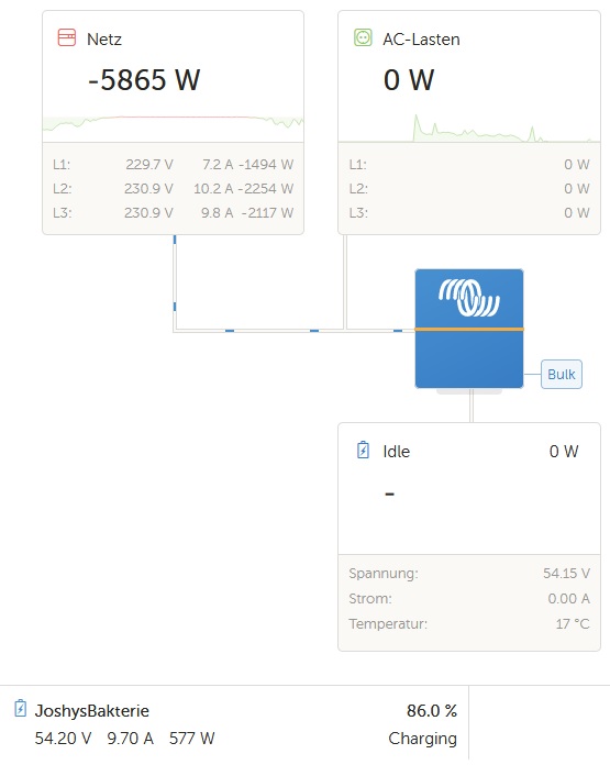
In the moment it’s discharging. About 6A.
Loaded up to 90% during the day at 5A. No imbalance warning from the Victron.
Imbalance in the moment 80mV.
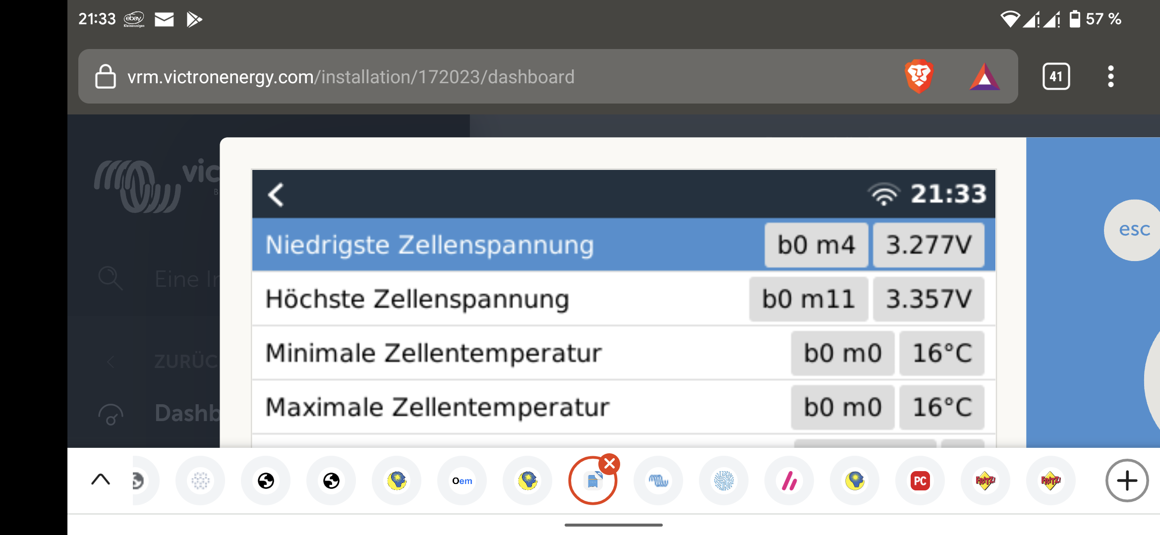
But I think the m4 Batterie is the one with the highest voltage during the day…
Nearly same timestamp.
Set the BMS to 10A max load. In the moment enough to load during the day i think.
Set the BMS to 1.5A when balancing. Works as I can monitor.
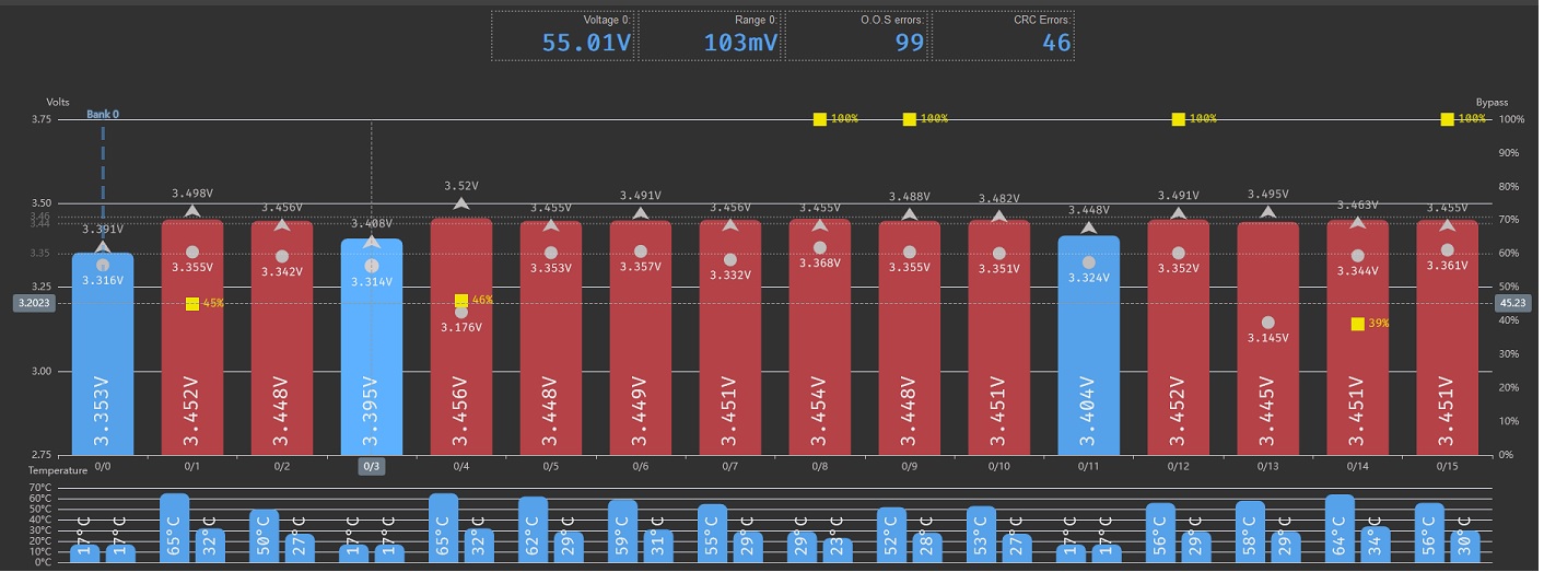
The Victron reduces to 1.5A. The BMS burns the cell which has too much voltage.
As soon as the situation is clear Vicky regulates back to 10A.
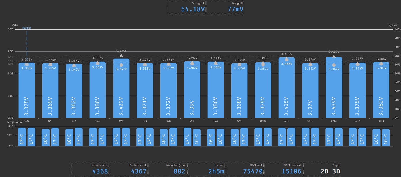
Seems with this the cells reach more and more nearer voltage…
yep that imho is fine, looks like system is improving.
It’s absolutely fine to have some/half/more than half cells red as in balancing as long as the current going in is not extremely high (more than 1.5-2A). reason being is that balancing (as in resistors burning current) happens as long as module temp is under the set value (circa 60-65C) once it reaches that and to avoid destroying the PCB/module, balancing stops. That means current goes into said cell, and voltage increases potentially over the set limits.
IOW, the reason for the 1.5A is that it manages to slowly stress/push current down the weak cells whilst fuller ones avoid getting overvoltage by burning excess.
Sorry if I’m re-typing known things, maybe useful for the benefit of newcomers…
I recon that once you manage to get all 16cells up there at 3.45V you have a “loosely” balanced setup, you could for a day try to up that to 3.5V (but be close by to check what’s happening) and even 3.6V.
But I wouldn’t do that regularly, once is enough. Then back to 3.45V, follow and see how the top of the charging cycle looks like and what deviation you have. If deviation is small, keep on using them like that.
If you see deviations increasing, you could do another carefully to 3.6 and back to 3.45 or so for daily use. From my reading this seems to be the recipe for cell longevity.
Current monitor is a brilliant tool in checking also what goes in capacity wise from 3.45 to say 3.55. You’ll be surprised it’s relatively little and imho not worth stressing the cells for that little benefit.
from my tests, 3.35V to 3.40V is not minimal capacity at all!
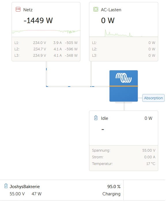
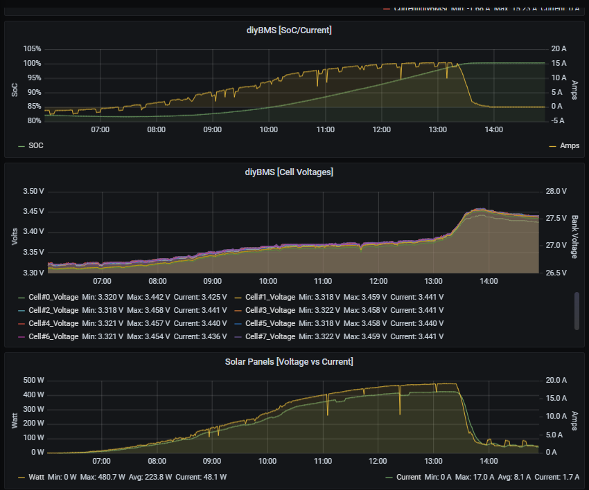
in the following graph it’s my 304Ah bank charging from 600W solar on the hardtop of my boat in Greece 10days ago (sunny day!)
from 9:00AM till 13:20 system was charging at max level attainable with this little solar.
9:00AM was 3.35V, 13:20 was 3:40V.
EDIT: that was roughly 30Ah (or 10% of my bank)
then indeed 3:40-3:45V happened quite fast and you’ll note on the top graph that charging current was limited by Victron:
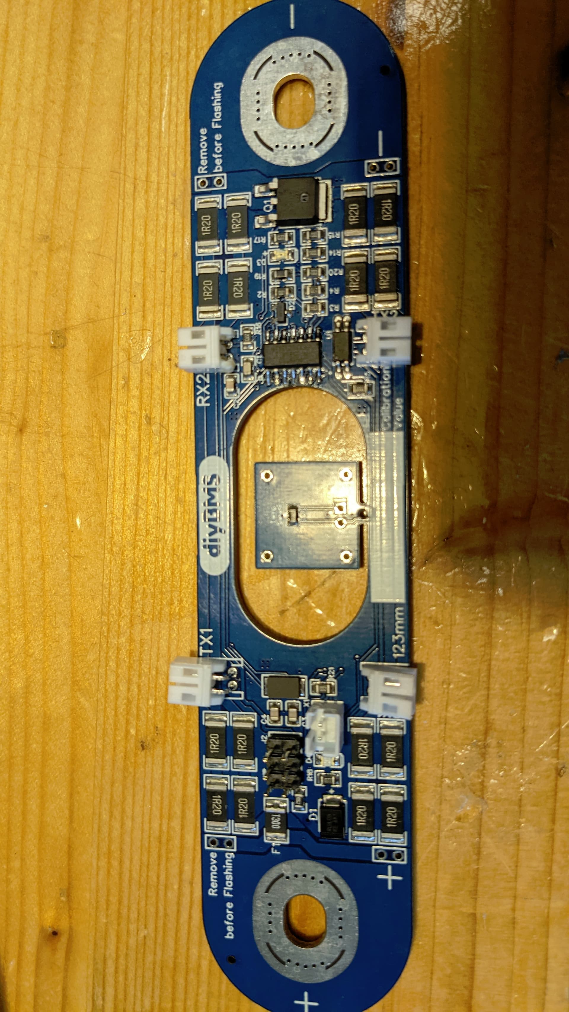
today I tried out my new cell boards.
I soldered an Attiny. Was the only part what was missing.
I flashed with success.
But when I connect it to my cells it does not work.
No flashing LED. No response to the controller.
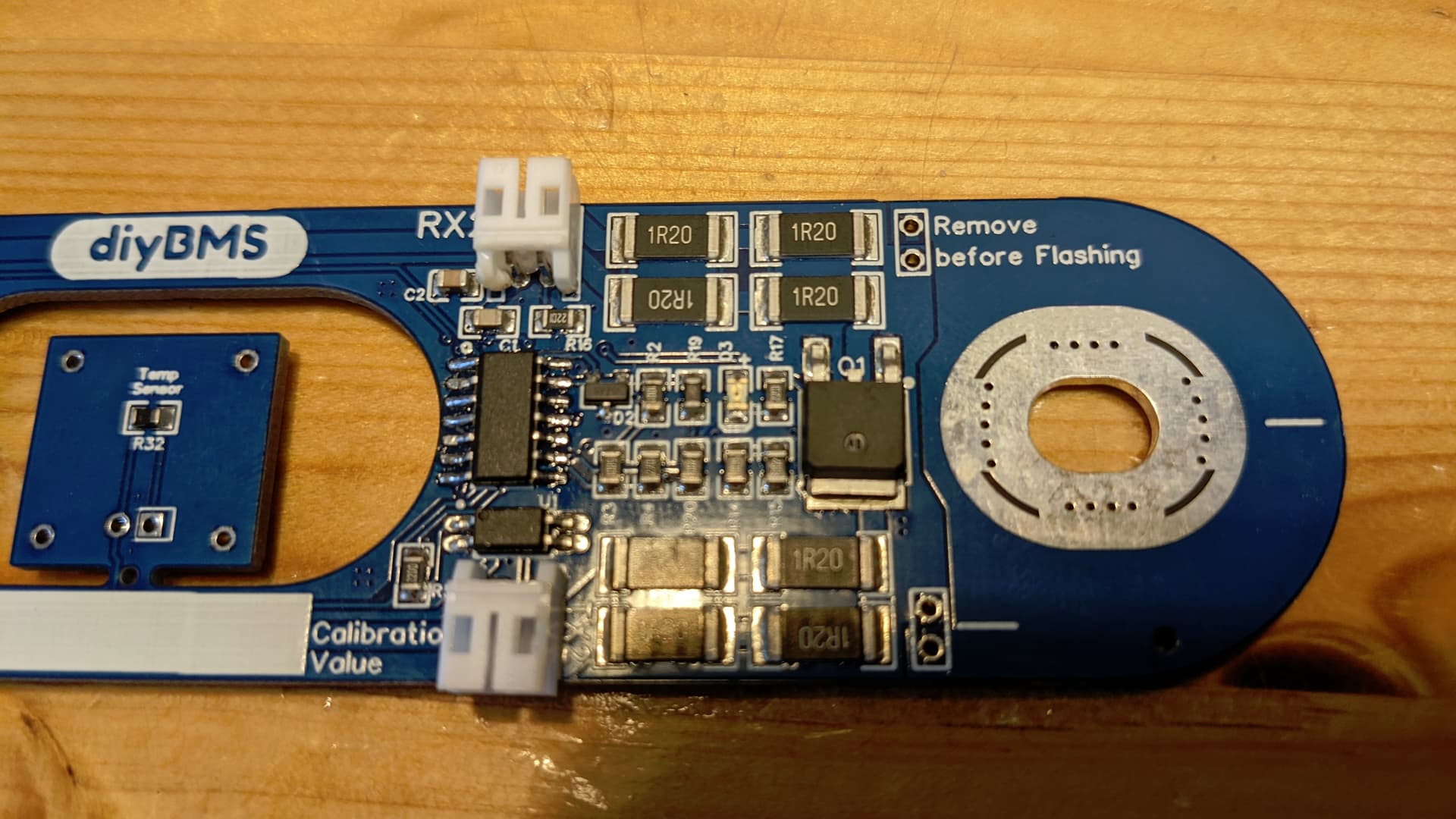
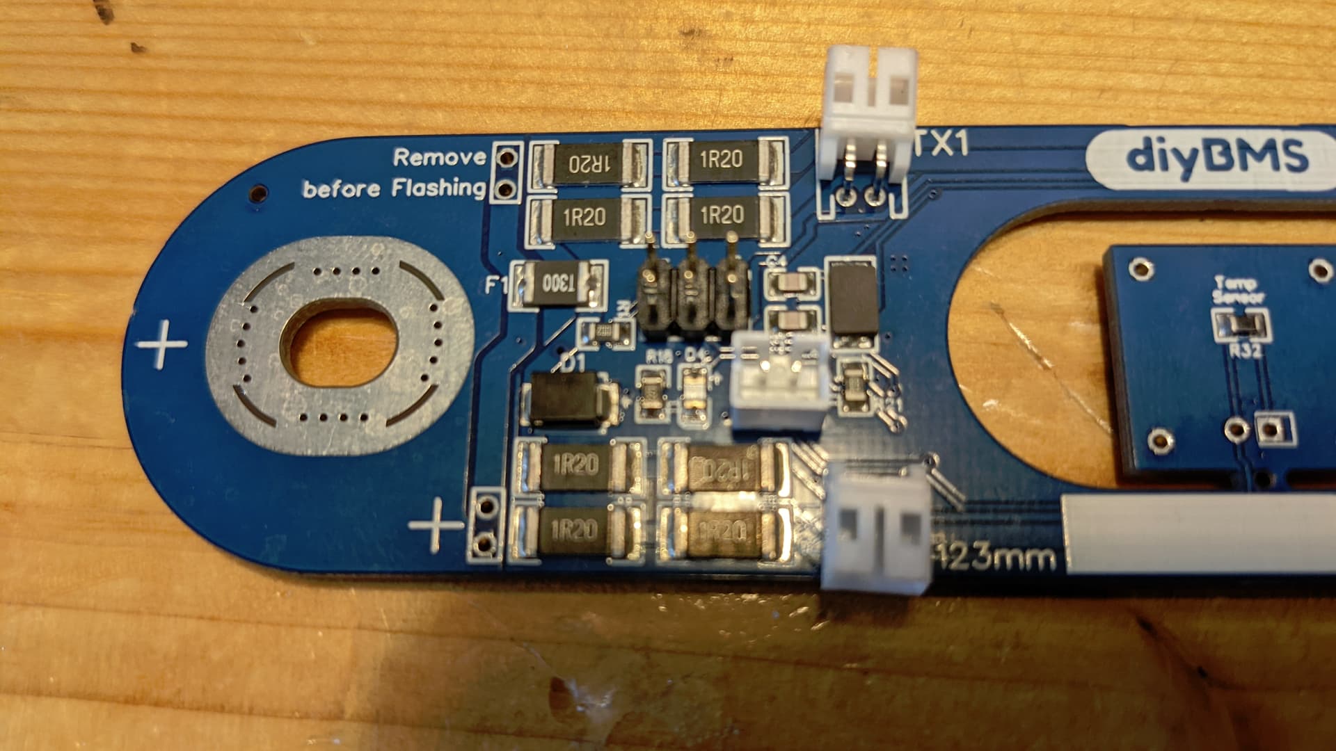
I post some photos of the board.
Maybe someone can see there is something soldered in the wrong mannor.
Or used a wrong part.
hi,
following @Andrew_Congdon (iirc!) suggestion I added jumpers on both sides, two on each side.
UNLESS you solder jumpers there and “close” them (as in put the connecting jumper on) there’s no current flowing from + to minus, basically pcb is dead, not live!
So, all’s fine, don’t worry, just add jumpers on both sides and bridge them!
the reason for adding two is that in theory they are 1A each, so 2 will cover the 1.4-1.5A we see on passive balancing without creating issues.
sorry about that,
the idea is that once you have everything plugged in and running, doing a s/w upgrade means you have to disconnect from the cell (at least that’s the theory!) The way this board is put together means that you just remove the jumpers, flash new code, reconnect the jumpers and off you go! No spanners, no danger of shorting anything.
hence the text remove before flashing on either side…
Ok. I see.
I did not mention this information far above.
I think its not very probalbly to upgrade a cell board.
When theres trouble its in the controller.
I have not time the next days to work on the system
I have now running normal 4.4 boads.
And in addition an active jk BMS.
I had 4 cells which do not load as high as the others.
One I took out and charged by a laboratory power supply.
And took it again in the system. Looking for what happens now.
If this is successful I will do with the 3 others the same.
I resetted the controller this morning before PV started charging.
To check the peaks for the next days.
I will be off home until Sunday.
Unfortunately I did still not manage to get remote access to the devices which are connected to my Fritzbox.
I’m not planning to take my bank apart anytime soon, and I’d find it amazing if @stuart et al don’t come up with firmware updates for the modules (as well as controller) for the next 3-4yrs. bringing out the torque wrench, messing with cables etc is no fun on a working system.
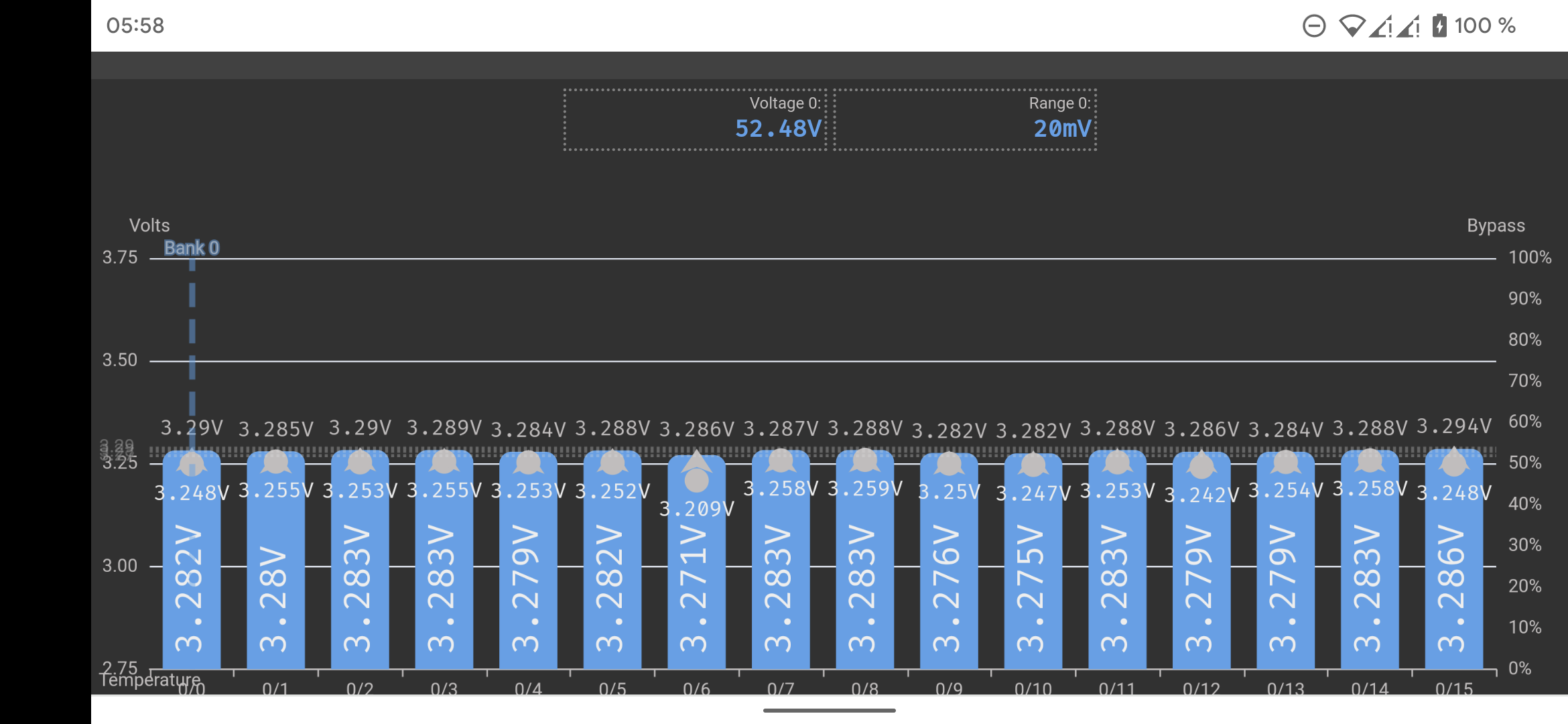
at 3.28V per cell any bank unless grossly unbalanced would look fine. Don’t know the load though.
My 8S 304Ah EVE cells are steady at 4-5mV throughout the range (and up to 50-60A) until it goes north of 3.4V. But I did balance them twice using a lab supply when I got them.
Having 20mV variation at 3.28V per cell, I’d guess that once you reach 3.45V per cell variation will be measured in hundreds of mV!
if you manage to throttle charge at 2A up there for a day it will most likely balance itself out.
An active balancer will help things further…
Your work on this board looks great. Many thanks for sharing this. Could you share link to your repo on github? I have EVE 304Ah cells and I don’t know if it will fit my cell so I need to print the board before ordering it.
There is no GitHub information.
The software you find in Stuart Pittaways GitHub for Cell board 4.4.
If you use the ESP32 controller the software is integrated onboard.
Thanks for reply. I’ve already seen that link to gerber files but I’m looking for link to Vas fork of this project… since it is open source project… i guess it should be also link to the fork
I have complete and working diyBMS with Stuart’s orignal boards… but the Vas fork looks a lot better for lifepo4 cell than the standard boards.