hey, its now in production and it looks like, that everything is right on place. Will update you again, when I will receive my (your) boards ![]() thanks a lot.
thanks a lot.
1 Like
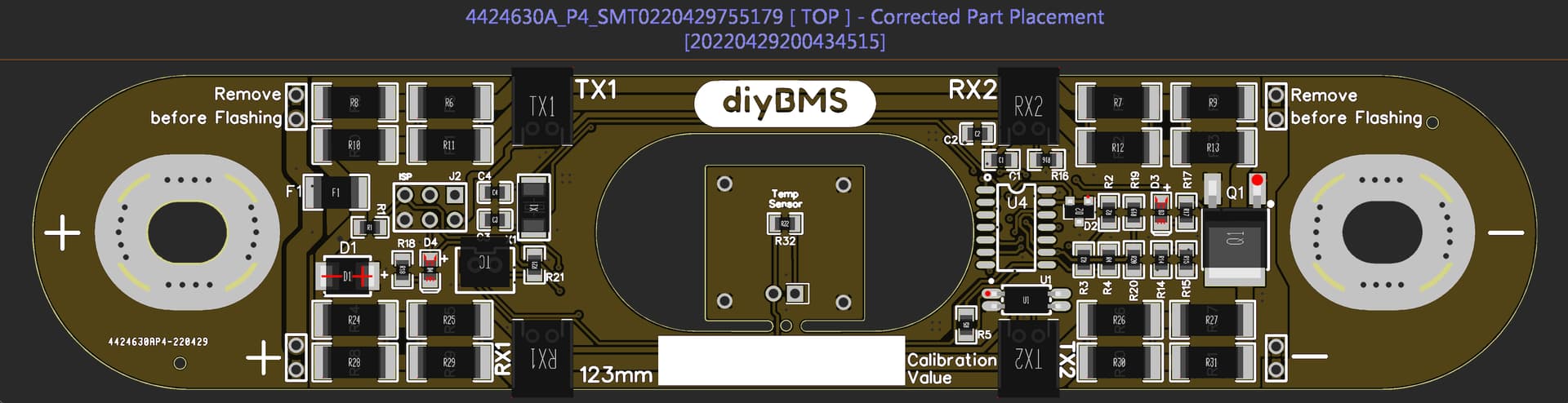
Hi there. My first post here. I´m from Germany and I´m working to built my DiyBMS from Steward.
I didn´t know that someone has made boards for prismatic cells.
I have a battery with 16 cells ( 280Ah each ) and want to use the BMS.
Is it possible to get 16 boards? Or better 32. I have two of the batteries in planning.
Attinys I have 50 here. Wanted to use them for the 4.4 version of Steward.
Where no in Stock at JLC when I ordered the PCBs.
So would have to solder them.
No, it’s not possible, that’s why I ordered 50 pcs and 5 pcs controller Bord.
Need two sets, will build all of them and will sell the remaining boards. Because no need.
Ps.
I am also from Germany ![]()
Schade.
If I got your question right, you can order multiples of 5, so if you want to make 2 16S banks, you can order 35 and have 3spares, or because the price is not that different, get 40 and have more spares ![]()
The question was: does anyone have enough boards to sell me some?
The answer was: no. However. I found your PCB data further up in this thread.
In the meantime I ordered enough. Thank you vas.
And an outher guy in germany has a complete large controller for me.
Assembled and programmed.
At first I wanted to use the small version.
But the CAN functionality gives me a better survillance of the battery.
I will try this out.
In the moment my Cells work without BMS.
For a few days it will be OK i think.
Measured the cells by hand. No reasonable drift in the moment.
But as soon as possible I want to use the balancer.
Best Regards
Meanwhile…
I built 16 “normal” V4.40 cell boards and have them connected to my batterie.
Controller ESP32 4.2. CAN connection with Victron GX.
It seems the BMS is not strong enough to balance all my cells.
One cell charges very fast und due to this begind to burn voltage very early.
I plan to install a JK active BMS in parallel.
You would be probably better off replacing the faulty cell!
1 Like
Have you top balanced the battery first? That would be quite normal for a new battery.
One of the original goals for the Lifepo4 modules was to allow more balance current than the typical boards.
If you take a look Off Grid Garage on youtube you’ll find a current discussion about leaving active
balancers connected all the time. The one I have has on/off contacts for an optional switch. I was contemplating using this to enable the active balancer at high battery voltage, perhaps using the shunt relay.
It could be equally useful at low state of charge?
I have two 16s batteries and have no problem with cell runaway despite them coming from different batches.
You want to enable cell balancing from about 3.5V and throttle charging at higher battery voltages.
The recommended settings found on many sites are way too high where there is no useful battery capacity anyway.
No, I did no top balance. Will try next week.
Didnt know about and read this information last days first time.
I get the fitting boards for prisma next week and will change to.
Saves much cables. And hopefully has a better performance.
Two questions to vas ( or someone who knows )
-
For what reasons are there two times RX/TX ports on the v1.9 board?
-
Which kind of passive colling heads may be used to glue them on the resistors to help cooling?
( lenght, width, or maybe type description )
These questions are answered earlier in this thread… in words and pictures ![]()
Would have been easier to get the anser written here.
OK. Found 9x9x11. Seems to be a very expensive solution. Costs per board quite same as the whole board.
But the answer of 2 times RX/TX is only while mirrored the PCB during CAD?
Strange…
when you have the bank setup each cell is + to - and so on.
If you try to run short wire runs, you’ll see that there’s no way to do so without having both sides occupied and choosing the one to use that makes the shortest run.
Assuming they are NOT available at JLCPCB right now (weren’t last time I ordered) just get the boards, order the right number of connectors and have a mock setup and decide which side you’re going to be adding which connector…
adding to what Andrew says above, on my 8S bank I start balancing at 3.45V and I have the CANBUS to Victron instructing and throttling charge at 27.7V to 2A.
This way bank charges nicely at the available Amps (solar so 12-16A in my case) and when it reaches 27.6V it starts smoothly lowering charge Amps. As a result the “Strong” cells start burning out and module temps are kept civilised (under 50C) for around 20-30 mins it takes for the “slow” cells to catch up. Then charging effectively stops (0.3-0.4A)
So before testing I’d avoid buying anything! I’m not sure that with decent top balanced cells you’ll need passive cooling.
V.
Ok. When I ordered They had all connectors.
No Attinys and not enough Mosfets.
I have a 16S Bank. Will try to start balancing at 3,44V.
“I have the CANBUS to Victron instructing and throttling charge at 27.7V to 2A.”
Where did you set this? In the ES32 Controller or in the Victron?
you set it in diyBMS/more/Victron CANBUS BMS:
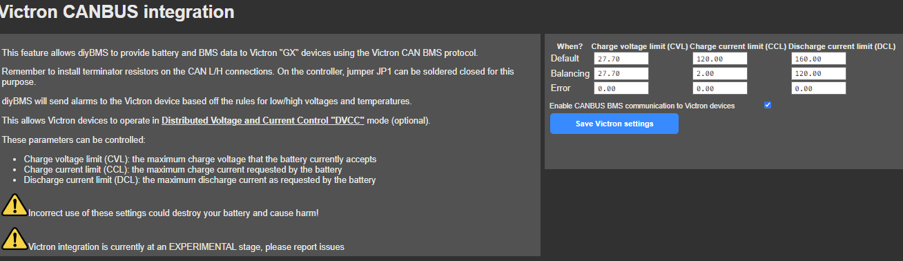
effectively what it does is your charging parameters (that is assuming your MPPT and mains charger/inverter ARE indeed Victron!) are not set individually on each device, but the Victron VenusOS (running on either a Gerbo or a raspberry pi) instructs the devices how much to charge when to drop, where to reach, when to stop. Of course on the Victron side, you have to configure DVCC mode, straightforward.
Very smart and works!
It means that your diyBMS will have to be connected with the VenusOS device. If it’s a raspberry you have to buy a canbus HAT and configure it.
well worth it.
V.
I have a Multiplux II GX 3000. Cerbo with Venus is integrated.
Charge Limit is 32A DC. About 2000W.
Discharge is some more. Up to 3000W. Shortly 5500W
I set the voltage in the BMS to 55V.
And the balancing to 10A.
But it seems it has no impact.
What settings did you take in the GX console?
VenusOS:
Settings/DVCC:
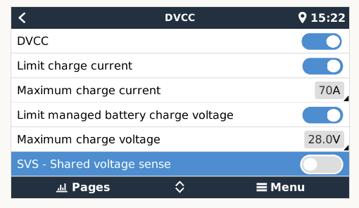
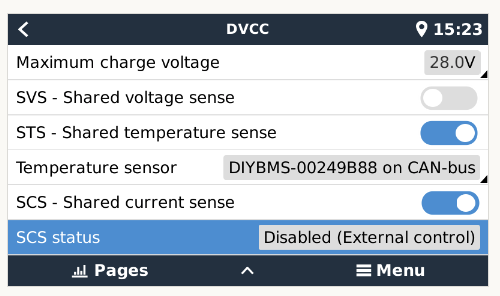
note the grey 28.0V maximum charge voltage, that’s because it’s set by the diyBMS settings I’ve mentioned in my previous post.
btw, 10A on balancing current is WAY TOO MUCH for the passive balancing.
The idea the way I got it is that you want to charge at full blast to JUST under where you want the balancing to start, and THERE, you drop charging current to circa 2A. But depending on how well you’ve tuned that, it’s going to be an hour max to bring the “tired”/“slow” cells up to the level of the others, then charging stops.
try to post screen captures of the settings you’ve placed if you want some more help
V.
1 Like
Have nearly the same settings.
Thanks for the hind with the Balance limit.
Will try.
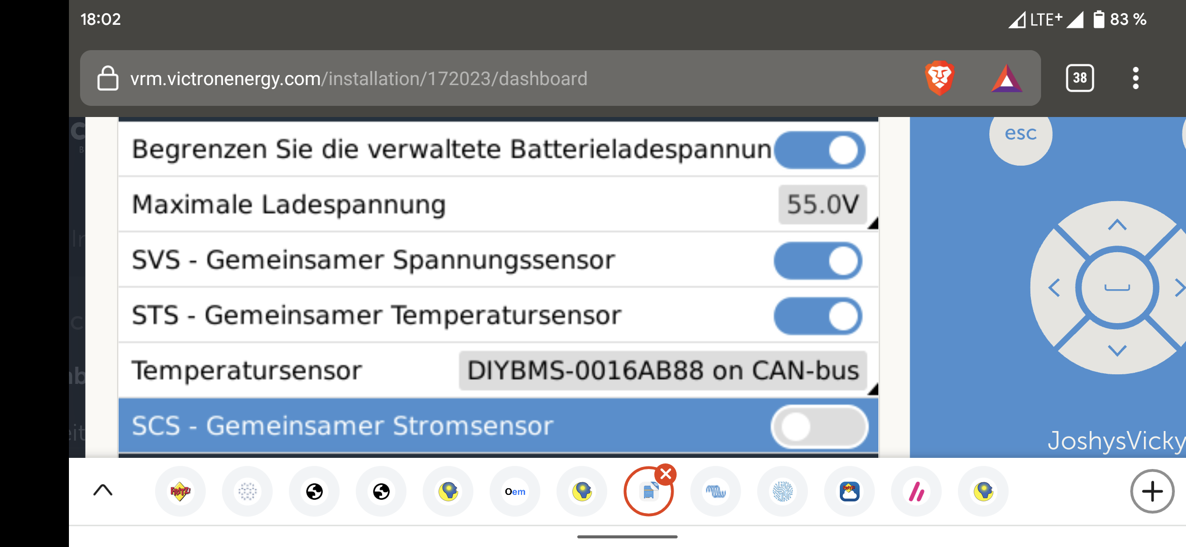
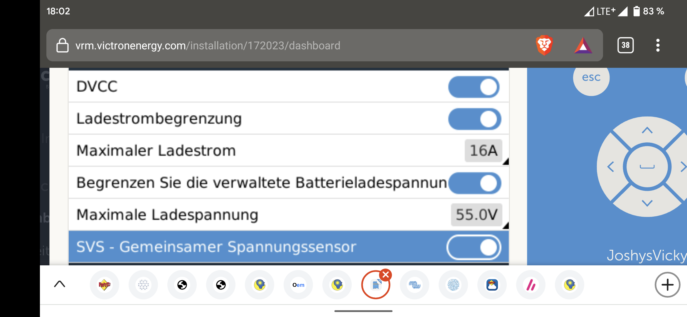
Settings in the DIYBMS accordingly.
I set load limit 16A… Balance limit 10A.
I said will be changed.
I can’t do it in the moment because I’m not at home.
Unfortunately my In nterner provider set my system behind a proxy and IPV6.
So I can t change anything via my fritz VPN.
Has to wait until Tuesday.