glad you like it stuart!
tbh honest if the underlying h/w & s/w wasn’t great I wouldn’t go into the trouble to mod @Jau board 
btw, from initial tests yesterday with just one new board, looks like on balancing it stays slightly cooler. Going through another balancing session with the four new boards so will know better later.
That latest design looks really good. Good to be able to easily see the vents.
The heatsinks certainly increase the sustained balance current although I haven’t measured it.
I have a working setup with the old boards and have put them only on the cells which regularly require more balancing.
They allow the 100% PWM indication to be maintained rather than being throttled for temp.
I don’t think they are required and may even mask issues like poor continuity.
I like the double nut idea. I’ve used thin copper washers between the nuts and boards so I can torque down the included nuts and be able to remove them without damaging the board.
My batch of 16 EVE 280 cells had 8 with welded studs and 8 with threaded studs.
I’ll have to measure and see if that leaves the same amount of thread exposed.

@Andrew_Congdon exactly, thin they are, enough to torque down at this small value at M6. Further means that replacing boards or doing any sort of maintenance doesn’t bring the whole thing down. OK, wouldn’t like to seriously charge or discharge the system at the time, but in an idle/low load state, it should be fine.
Completed some testing with my 8S system where the middle four are the new v1.9 modules and the two on each end are the older ones.(as per the pic I posted yesterday above).
Balancing starting at 3550mV, top balancing with a bench supply where I can accurately tune Amps going in. Bypass overtemp at 65C, room temp 21-22C, results:
@1.2A new modules at 45-55C, old modules at 55-65C Managed to keep that indefinitely - OK, got bored after 20mins but didn’t really look like changing:
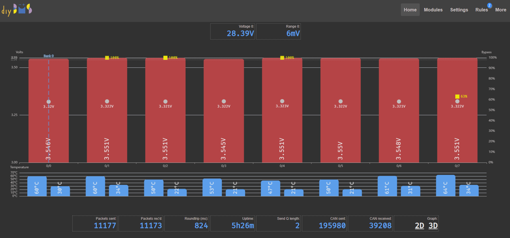
@1.5A new modules at 55-60C, old modules at 68-73C. Could not keep it for v.long as old module cells voltage kept creeping up as expected:
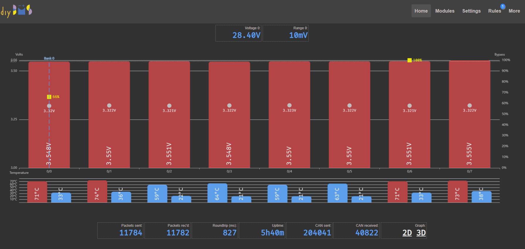
interesting to see the influx data in grafana (at 60sec interval though so relatively rough) where it clearly shows the split between the old and new modules internal temps:
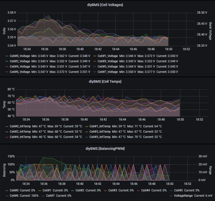
Conclusion, looks like the split of the pcb in two parts helps in keeping the pcb cooler (will try with my IR thermometer as well but tbh cannot see that changing!) allowing for a slightly higher balancing current of 1.5A. These tests were done in order to decide on the Victron CANBUS integration Charge Current Limit (CCL). So looks like I’m sticking with 1.5A with no force cooling and heatsinks. May have to reconsider in July Med weather onboard though
cheers
V.
First a big thanks to everyone who contributed so far.
I am glad i found this because it seems to be the perfect solution for a BMS for my 16pcs LiFePo4 280 AH.
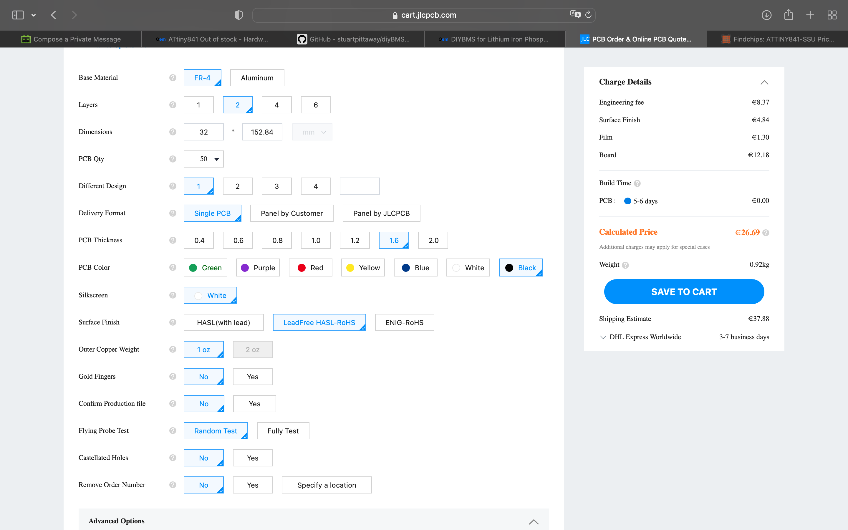
I am about to order the pcbs at jlcpcb.
So far i only found the V1.8 from Vassilis.
Are the ZIP ( or files ) somewhere i did not look yet?
I think i will order it with assembly as i am not so good in soldering the tiny parts.
Thanks again
regards
Joerg
sorry,
was too busy with other things.
V1.9 is 123mm only (ok, holes are oval so got ±0.5mm), built,tested and working fine now for almost two months at my 304 8S setup.
the new Q1 surprisingly is also back in stock!
EVE_v1.9F.zip (121.9 KB)
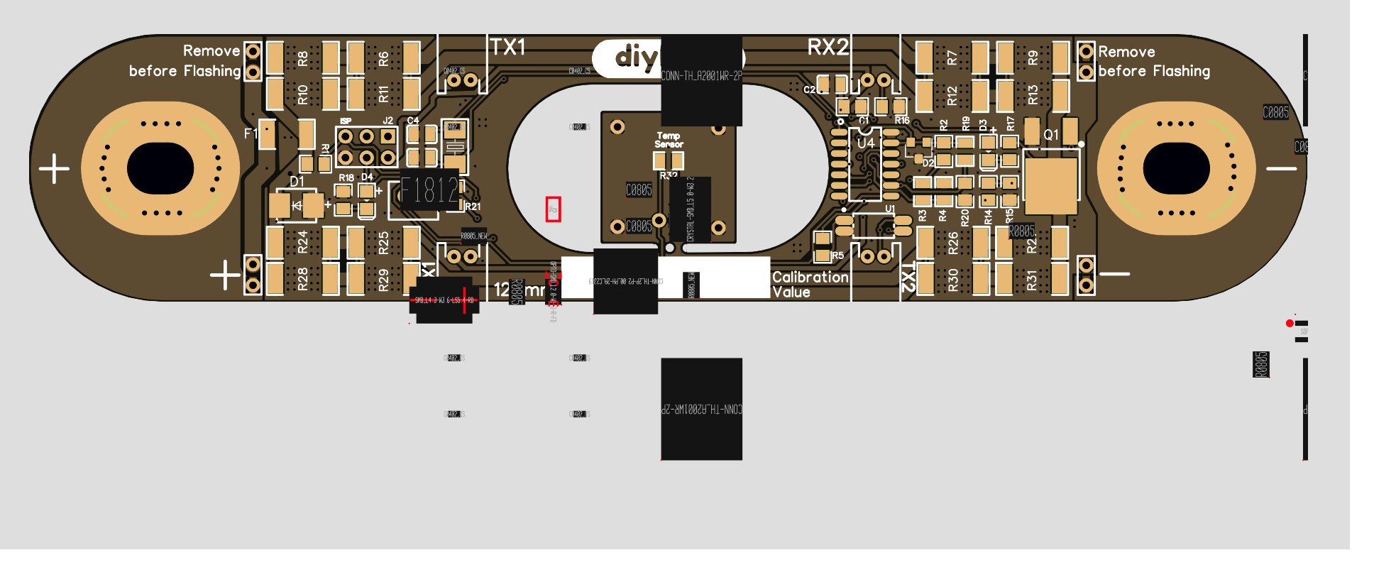
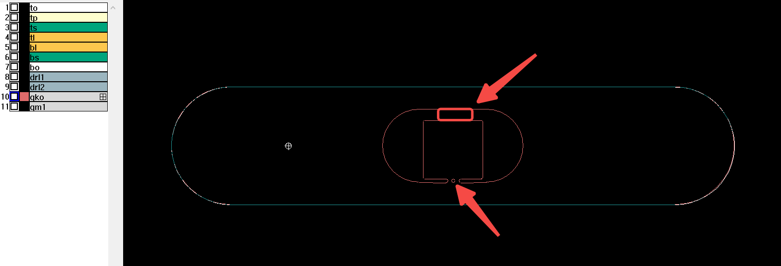
Note that this design has a “hole” in the middle through which you can examine the vent on each cell as well as read the QR code without having to take everything apart.
This hole has the second thermistor that can fit on the side of the cell. I oversized them to make them easier to stay put with some doublesided or other tape.
YMMV, I was charged extra 8-10usd for them, I don’t mind that, you may be lucky and not charged. BTW, I’ve got tracks from the main pcb to this thermistor board so without breaking it away it will function as second temp sensor (albeit slightly pointless when it is 50mm away fro the pcb mounted one…)
Also note that by splitting the resistors apart, PCB seems to heat less (without heatsinks) so I can sustain 1.2-1.5A balancing at 20C ambient. Guess wont be that high onboard and with 30C ambient.
Final warning since I built my pcbs in blue and I generally avoid green leds, I replaced D4 for a blue led. Easy enough to swap over for a green if you wish on the BOM csv file.
cheers
V.
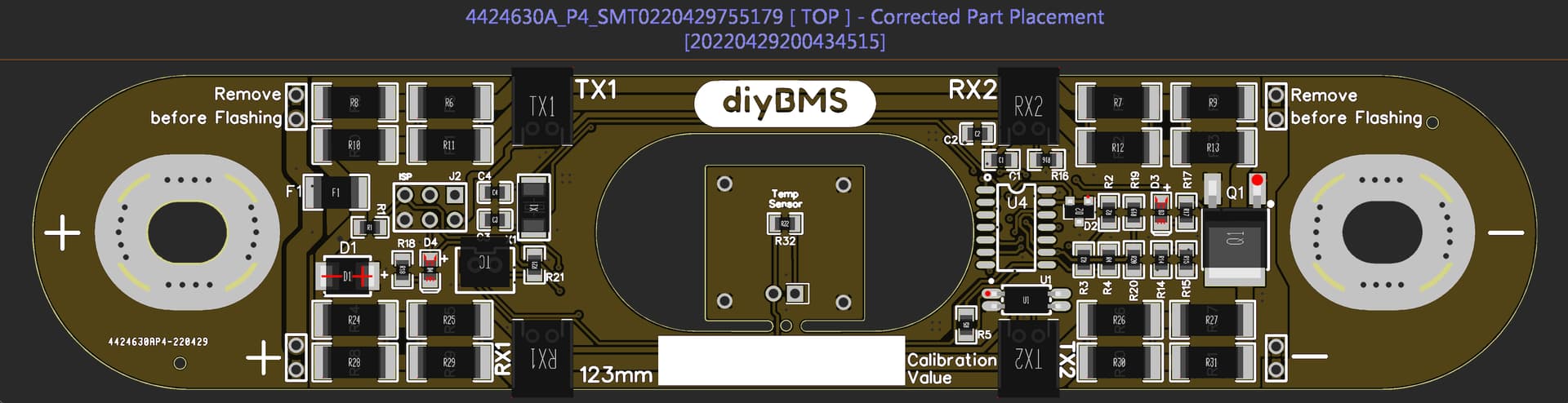
thanks a lot @vas ![]() when I import the pcb on jlc everything is fine. but afterwards, when I add the BOM/ CPL the parts looks very misplaced on the preview. is it normal? or could you post the “config” nr, that it would be possible to reorder your specific one, but for myself?
when I import the pcb on jlc everything is fine. but afterwards, when I add the BOM/ CPL the parts looks very misplaced on the preview. is it normal? or could you post the “config” nr, that it would be possible to reorder your specific one, but for myself?
thanks a lot
odd, can you please post a pic of the settings screen and where the components are placed? maybe you’ve mirrored something in the settings?
@vas
hey, great to hear from you, thought the same,
and on version 1.8f its looking in preview pretty well placed, but in 1.9f its… messed up, but hopefully, I made the mistake :-).
sometimes I’ve seen this. It looks like it’s different scale, not mirrored.
Try again may work. If you’re brave you can send your order and they’ll figure out the issue and scale/short it as the info is there for sure!
sorry cannot be of any more help (and I don’t even know what you mean by config - don’t think there is one in JLCPCB
V.
hey @vas,
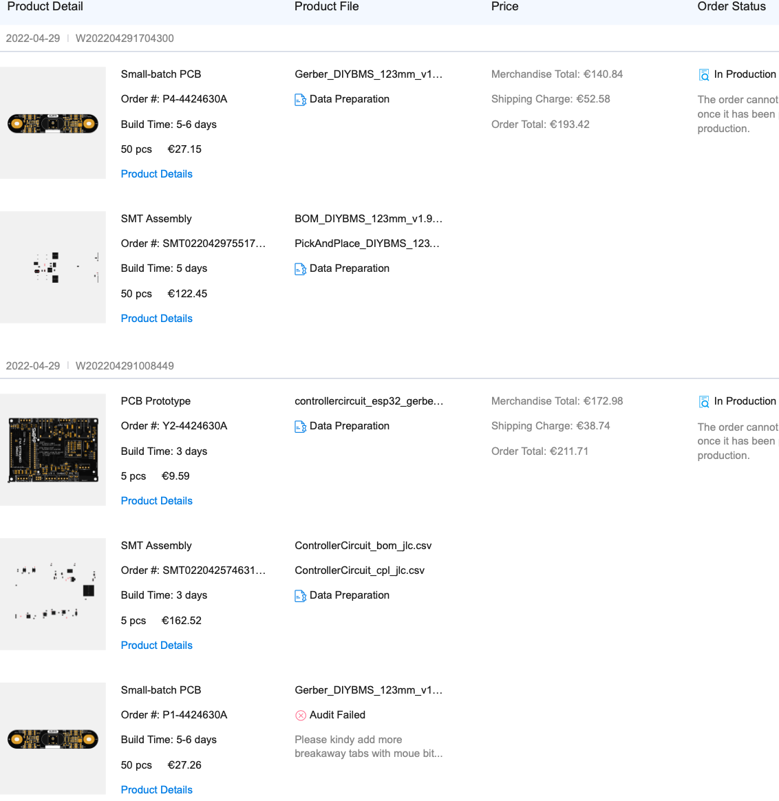
tried to order now the v1.9f but got this reply:
Please kindy add more breakaway tabs with moue bites to avoid the small pcbs falling off during production and the width of breakaway tab is required 5mm at least.
got you have a look? thanks a lot
interesting (not!)
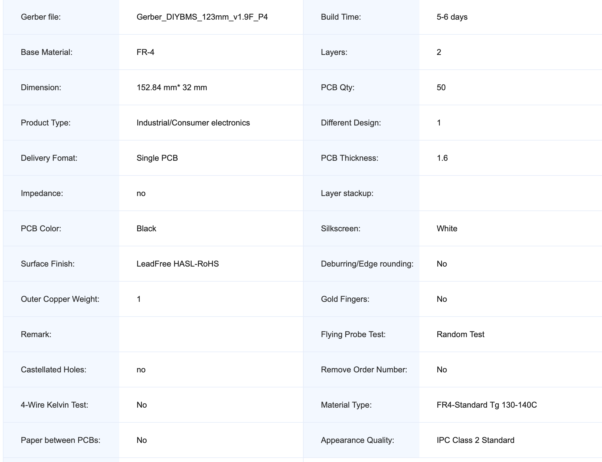
did you use default standards for the PCB?
I mean FR4/Industrial-consumer electronics/1.6mm/HASL with lead/1oz?
judging from the force needed to break out the temp sensor bit, their claim of falling off is at least ridiculous!
okay, it looks like, now at the new upload it was no problem at all…
Will update you again. so even with “preview failure” it was now approved. we will see
looks like its a hit or miss, and relates to the real person that has a quick (I guess) glance at your design at the time. hence sometimes, you just cancel resent and it goes through without changing a thing!
good luck ![]()
hey, its now in production and it looks like, that everything is right on place. Will update you again, when I will receive my (your) boards ![]() thanks a lot.
thanks a lot.
1 Like
Hi there. My first post here. I´m from Germany and I´m working to built my DiyBMS from Steward.
I didn´t know that someone has made boards for prismatic cells.
I have a battery with 16 cells ( 280Ah each ) and want to use the BMS.
Is it possible to get 16 boards? Or better 32. I have two of the batteries in planning.
Attinys I have 50 here. Wanted to use them for the 4.4 version of Steward.
Where no in Stock at JLC when I ordered the PCBs.
So would have to solder them.
No, it’s not possible, that’s why I ordered 50 pcs and 5 pcs controller Bord.
Need two sets, will build all of them and will sell the remaining boards. Because no need.
Ps.
I am also from Germany ![]()
Schade.
If I got your question right, you can order multiples of 5, so if you want to make 2 16S banks, you can order 35 and have 3spares, or because the price is not that different, get 40 and have more spares ![]()