I use an Elkor WattsOn power transducer which gives me (via Modbus) separate
measurements for PV power generated as well as Leg1 and Leg2 consumption.
I went that route for a few reasons.
I wanted resonable accuracy without the need for calibration before use
I wanted to be able to use 333 mV CTs
I wanted a Modbus device.
That may have been overkill, but at the time (~4 years ago) the WattsOn was the cheapest solution.
(cost ~$75)
Having a fairly straightforward setup, all I wanted was PV generation and overall consumption data. What little math I do gets done in the Python script that reads the meter, which then sends the calculated values to Influx.
In 2018, nchaveiro posted this:
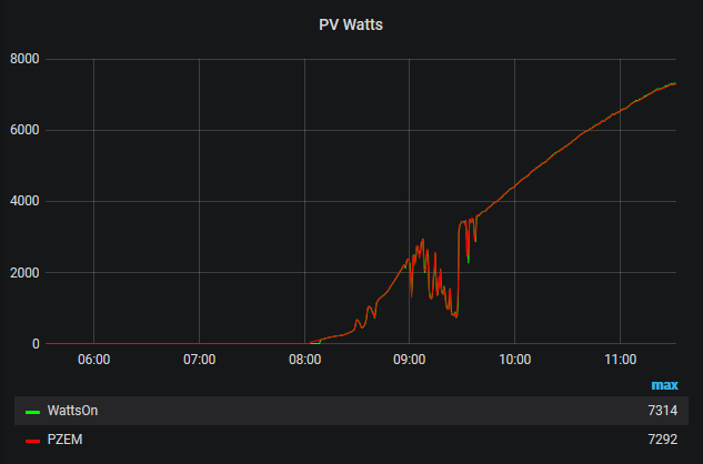
What’s surprising is it’s actually fairly accurate. Not bad for a 10 buck device!
Here’s a shot comparing the two:
At 10 bucks a pop, one could use three of them to make the measurements, do the math
in a Python script, then send the data to Influx. Total outlay would be less than 50 bucks.
Sorry to get so long winded on ya. But I don’t really have any suggestions to offer.
Absolutely no worries… I have a workaround in mind that won’t be difficult at all to implement.
Robert, I’ve added a 10nF plastic capacitor to a single CT input as you’ve suggested. The chart below is with the CT leads connected to my Pi, but with the CT disconnected from the panel. (Actually, the blue sample was taken while all the other leads, except the one in the data sample, were connected to the panel, and the red sample was taken with all 4 leads not installed in the panel. Hopefully there isn’t any crosstalk/interference between the twisted pairs that is a factor, here).
How do these look to you? Should I try with a 22nF capacitor?
Also, despite the visible evidence of the noise being reduced, my code’s calculations on the raw data are still showing 0.3A when the CT sensor is not even around a conductor. I’m debugging my code to investigate this recurring ~0.3A value that we’ve called “noise” - and interestingly enough, my scaling factor for each CT sensor is just about 0.3.
I’m going to feed it some fake data where all samples are neutral (510), and see what it spits out. My bet is that it will show me 0.3A still, which would obviously be a bug!
Well, turns out my code is sound for completely neutral data sets. Real Power and RMS current all came back as 0 when I fed it 511-514. I guess that leaves trying a larger capacitor (22nF, then 47nF) to flatline the noise.
Also, just wanted to share that when I tried the 10nF capacitor, I had to make a substantial adjustment to my correction factor for the CT circuit the capacitor was applied to. Substantial, as in a few hundredths less than before. I’m trying to understand the theory of why adding a capacitor would make the current read higher. Is it because the capacitor can’t charge and discharge fast enough to keep up with the 60Hz waveform, so the “filtered” input signal looks different than before?
Edit: I just read this section on the time it takes to charge a capacitor, and it looks like one “time constant” in my particular circuit is 21Ω * 10nF is 21E-12. I would say that three of those time periods (to get to 99% of the line voltage) is negligible when it comes to a signal changing at 60Hz. I don’t quite understand the theory of how capacitors actually act as a low or high pass filter yet, and I’m sure there are optimum capacitance values for that aspect… but from a time-to-charge perspective, I think I’m fine well above values of even 100nF. I’ll try 22nF on another input channel now.
OK, I didn’t think you’d made that mistake but it was an easy one to check. The harder check will be to work out the rms value of the noise by hand. It’s not difficult, just tedious. You count the population of each value in a representative sample, then do the “square root of the mean square”. Apply your scaling factors to convert counts to amps. That will establish the accuracy of your code to a high degree of confidence.
What’s the correction factor? Do you mean the phase error correction? If you do, I expected that. You’ve created a low pass filter, and all simple filters like that introduce a phase shift. The fact that the current read higher meant is was not right to begin with.
Yes - it’s the one that adequately suppresses the noise but doesn’t cut off the higher harmonics that should be included in the measurement. Some people have tried very aggressive filters, and proclaimed their benefits, not realising that they’re missing some of the current they should be measuring. Like a lot of engineering, it’s a balancing act.
The 22nF capacitor on another channel doesn’t appear to dampen the noise any more than the 10nF capacitor does on the adjacent channel. Here is a chart that shows 3 different results. Ct0 with a 10nF capacitor, Ct1 with a 22nF capacitor, and for comparison, Ct1 before the capacitor was applied.
Current is still calculated at about 0.28A (with the red line as the source data in the 0.28A result). I did not do any corrections for phase difference - could this be the root of the issue? If the neutral values aren’t exactly in phase with the “zero” of the voltage waveform, then there would be some false current calculated, right?
Here is a plot from data I just took. It compares voltage to the CT sensor with the 22nF capacitor applied. My first thought was… what in the world happened to my AC transformer output? It was a perfect looking sine wave when I started - see post #67
I know it is very difficult (for me at least) to see whether or not there is a phase error in the chart above. If you think phase error is the problem… could you point me to a mathematical process so I can calculate it on my own?
What are we looking at there? If the red trace is voltage, was your transformer connected? You had a swing of 800 counts p-p earlier, now it’s only 50 at best.
Whoops, I forgot to add the legend. I just replaced the image in the previous post. You’re right - the voltage does look to have an abnormally small amplitude. Let me make sure there’s power to it and I’ll pull another sample set. I’ll also test the AC voltage from the plug. Be right back…
I still have the original circuit built on the breadboard from the earlier posts… I could try collecting the AC transformer values on that board to eliminate my board’s circuitry. I will answer your previous questions in my next post…
No - I didn’t do any phase correction (at least, that I’m aware of). The correction factor I’m referring to is the static value I’m using to tweak the output of the Current calculations to match what my clamp meter shows.
More specifically, the correction factor is here in my code. It’s basically a fixed percentage value below the neutral level of the ADC. It gets applied in line 192 when calculating the real power, and also in line 205 when calculating the RMS current. Until now I have thought of it as a necessary correction to account for the unique tolerances of each circuit and CT sensor, but now I’m back to questioning if how I’m doing my calculations is correct or not.
The only actions I’ve taken regarding phase is choosing the order in which each circuit is sampled. Right now, it’s CT0, CT1, Voltage, CT2, and CT3. That probably means that CT1-2 are more accurate than CT0 and CT3, but I haven’t done anything to investigate or correct for the phase error.
That’s really interesting. My voltage calculations in my code are still looking correct.
You could look at emonLib and emonLibCM for two closely related but different ways of solving the problem.
emonLib is the “old” discrete sample library that measures pairs of samples (V & I) ‘on demand’ for a short period, then moves on to the next pair. The d.c. offset is removed on a per sample basis with a low pass filter extracting the d.c. value, then the maths subtracts that before the averages are calculated and scaled. There’s also interpolation to derive a time-adjusted voltage to align the V & I samples, taking into account the sampling interval and the transformers’ phase shifts.
emonLibCM lets the ADC free run, picking up the values in an ISR. So it samples a lot faster, reading a full set of (normally) 1 voltage and 4 currents in sequence before repeating that continuously. In that, the minimum of processing is done per sample, and as much as possible done per report. So the nominal offset is subtracted to make the numbers (particularly the squares) smaller, but the cost is the average also needs accumulating because we won’t know the average - i.e. the offset remaining - until that averaging interval is complete. Also, the interpolation is done per report rather than per sample. It makes for simple and faster processing per sample, at the cost of some complexity per report.
I wouldn’t bet on it - it depends heavily on the relative phase errors of the v.t. & c.t.
Having looked at your code, I see a couple of minor points. First, you appear to be measuring but not using ref_voltage. Or was it a sanity check on the average raw number?
Second, yes I think you do need “correction factor” - it’s roughly a calibration coefficient and it will be necessary because of component tolerances.
I published the maths for phase errors etc in a pdf. Ignore references to transmitting data to emonhub etc, the same maths is used inside emonLibCM.
Thanks for looking through it! If I had known you were going to analyze it, I would have cleaned it up more.
What you are referring to is likely the function definition for get_ref_voltage(). In a previous version of my code, I was using this function to get the actual reference voltage (~1.65V) from one of the circuits on the board to subtract it post-ADC-output conversion. I now subtract the average ADC output value from the sample so I no longer care about the reference voltage. The call to the function is commented out in line 313. So, the value is never measured in the current version of the code.
I’m glad I am on track there…
Thank you for the document. I’m out of time to commit to this tonight, but I intend on starting with this document tomorrow. I’ll also revisit the theory in the Learn section of the site.
Thanks again for your continued support - you’ve been awesome! This project would most likely have fallen aside if you weren’t so generous with your time, knowledge, and patience.
I’m looking into having a custom PCB made. I’m not really satisfied with how I had to stack two of the Raspberry Pi perma-proto-hats on top of each other because I couldn’t fit all the circuitry on one board. I have a feeling that is contributing to the noise. And, since I’m this far in already, I might as well go the extra mile to learn a little bit about PCB design. Furthermore, with the likely manufacturing delays due to the virus outbreak, I wanted to get an order in and use the waiting time to investigate the phase correction.
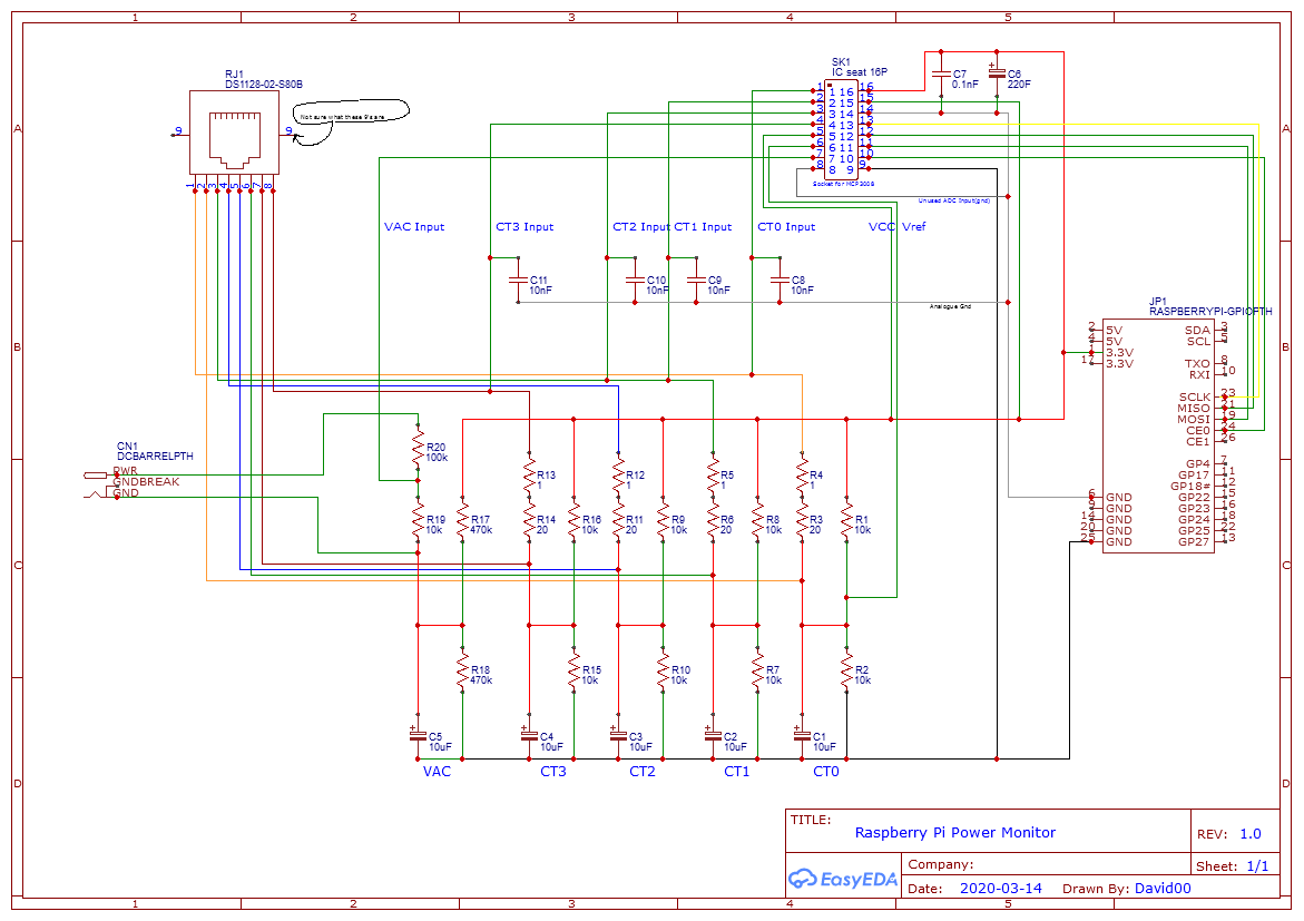
I’ve built my schematic already and I’m working on designing a custom Pi Hat that will fit over the Pi and connect to the headers. I’ve never done this before, so any advice, suggestions, or corrections are greatly appreciated! Here is my current schematic.
Why not use the buffered bias supply (see Learn | OpenEnergyMonitor) given that you have 5 identical bias circuits?
Also, do you really need the 20 Ω & 1Ω in series? I’d question whether it is worth the extra cost and board space. If you are tied to E12 series resistors, you’re only gaining 5% on the useful range of the ADC, if you can obtain an E24 series component, you can have 21 Ω exactly.
I’d put a inductor-sized link in the 3.3 V line from the RPi, just in case you need it for more filtering.
Posted today in another thread is an input circuit incorporating input protection for the ADC. You might want to think about that before committing your board to manufacture.
A wire link that you can remove and substitute a series inductor, if you find you need additional filtering on the power supply to the bias circuits and the ADC. So you have an inductor that presents a low resistance to d.c. but an increasingly high impedance to a.c. as the frequency rises (therefore it blocks a.c. noise on the supply) and then the capacitors you have attenuate the a.c. component even more. In effect, you’re introducing a frequency-dependent voltage divider into the supply that lets the d.c. through unhindered, but blocks a.c., and the higher the frequency the better it blocks it.
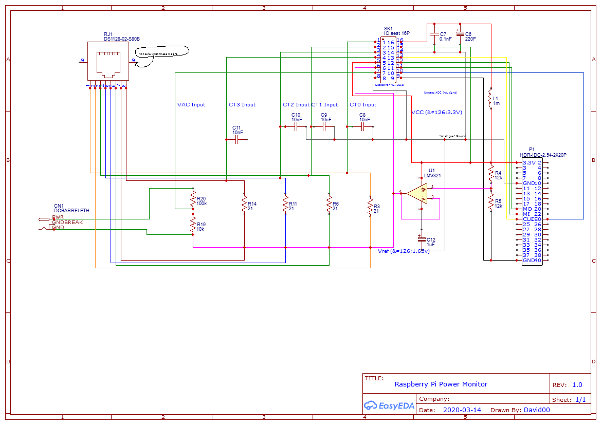
Thank you. That makes sense. I’ve added the buffered bias supply, an inductor (which I’ll use wire to connect unless an inductor is needed), and I revisited the subject of analogue vs. digital grounds. Since the Pi’s ground pins are all on the same bus, I can’t really separate the analog grounds from the digital ground. Can I use an inductor or filtering capacitor either inline or between the two grounds to help reduce the transfer of noise through the Pi’s ground bus?
Also, should my decoupling capacitors on the ADC input pin #16 (Vdd) be connected to the Agnd on the ADC, or the Dgnd? Right now they’re connected to the Agnd, but I think they need to be moved to the Dgnd (pin #9).
That might be worth doing - if you have it, you can always put a link there if it actually causes trouble. The main point is not to allow digital current to flow in the ground traces that link the analogue parts.
You’re probably right, but refer to the data sheet or App. Notes for guidance on that. You might need to determine the relationship between pins 6 & 25 on your RPi to get all the relevant information.
In any case, those grounds appear all mixed up. ALL the analogue circuitry needs to go to a clean ground - the ADC analog ground, the op. amp, it’s input voltage divider, and the filters.
You’ve got L1 in the wrong place - it needs to be before the half-rail divider for the op.amp. You’re not too worried about noise on the 3008’s VDD, it’s VREF that must be clean - if there’s noise on the reference, what chance do you have of making meaningful measurements? Get a copy of Microchip’s AN688 and study that.
I hope your PCB is large enough to accommodate a 220 Farad capacitor.
And take a careful look around U1 - that’s gone wrong big time. C12 should go onto pin 1, and pin 2 to AGND.