Hi there,
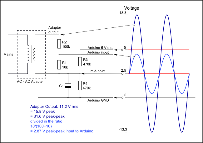
I’ll try to keep this post brief and to the point. I’m currently building a home power monitor using a Raspberry Pi Zero W and the circuit diagrammed here: Learn | OpenEnergyMonitor. My circuit uses 20 ohms for the burden resistor between CT leads. I’m in USA and I’m using a 120V 60Hz AC circuit for testing.
It is functional, but when I calculate the load of the conductor my CT sensor is monitoring, it doesn’t match the load that a power meter is showing (ie, Kill-A-Watt). I put a 700W load on my test circuit but my calculations using the data from the CT sensor only show about 390W. I have measured the load using two different commercially available power meters, and it is in fact about 700W.
I have reviewed the entire OpenEnergyMonitor AC Power Theory section, which, by the way, has been a fantastic resource, so thanks to the community for providing such a valuable source of knowledge. I have an understanding of the theory, but I’m not sure where the source of error is coming from.
Here is how I am calculating the power usage:
- I take 120 CT sensor voltage readings as fast as the RPI can handle it, which is in between 1-2 seconds.
- Find the minimum value and maximum value from the 120 readings (one value is negative, the other is positive, but the absolute value of them should be very close)
- Calculate the min/max values as a percentage over/under the reference voltage of 1.6580V, or half of the 3.3V Raspberry Pi rail)
- Average the two percentages to get the average peak CT reading.
- The amperage is simply the percentage previously calculated of the 100A CT sensor capacity.
- I assume (for now) a 120V AC source voltage, so I multiply the amperage by 120 to get the power being used.
An example with real measurements just taken with my 700W load is (I am rounding these to 4 decimals to save space below, but my program is using the full value of the floating point number):
- Min and max values from 120 CT sensor readings: min: 1.6033V | max: 1.7124V
- % under reference voltage: (1.658 / 1.6033) - 1 = 0.0330
- % over reference voltage: 1 - (1.658 / 1.7069) = 0.03282
- Average over/under reference voltage: ( 0.0330 + 0.03282) / 2 = 0.03291
- Amperage on the line through the CT sensor is 0.03291 * 100 = 3.291A
- Power being used = 3.291 * 120 = 394W
I’m not sure why my power calculation is low. I realize I’m not using the standard “Real Power” and “RMS Current” methods, but from my understanding the method I’ve outlined above should be working fine. Especially since the CT sensor’s output has been measured to provide linear values until saturation > 100A (on the openenergymonitor site).
Another issue I’m having is my program calculates a 0.9W load when there is no current flowing through the conductor. This won’t be a concern when I hook the CT sensor up to my house mains since I’m sure the load will always be measurable, but I am just really focused on accuracy at the design/testing stage.
Thank you for any assistance!
Edit: After reviewing my post and going back through the circuit diagram, I’m starting to think that the “reference voltage” (as I’ve termed it) is not needed in the calculations. The analog input going to the Pi/Arduino has nothing to do with the reference voltage - that’s only serving as the path to ground for the CT sensor. I’ve modified my current calculation to simply be the difference between the peak voltage measured from the CT sensor and the reference voltage. This has gotten my power calculation closer, but still not to a level of acceptable accuracy.