That doesn’t follow. If that peak moves slightly sideways one way or the other, the power factor will change markedly.
If you were to have a pure capacitor as a load (DON’T try it), you should get a p.f. of zero.
That doesn’t follow. If that peak moves slightly sideways one way or the other, the power factor will change markedly.
If you were to have a pure capacitor as a load (DON’T try it), you should get a p.f. of zero.
Ok, thanks. And don’t worry, I’ve had the unpleasant experience of being shocked by a charged capacitor used for the flash in disposable film camera… I learned the hard way!
If you post a picture of your breadboard, that might help.
If I were making something like this, I’d use Veroboard (https://uk.farnell.com/productimages/standard/en_GB/1536938-40.jpg).
Pack everything in as small an area as possible with the shortest possible interconnections everywhere and the shortest possible wires to your RPi. I’d decouple the 3.3 V supply with a largish electrolytic capacitor (220 µF or so) and a 100 nF ceramic disc capacitor in parallel, physically close to where your power comes in, with a second 100 nF as close as possible to the ADC’s power pins.
Ground all unused tracks and don’t leave long ends on the used tracks.
That will be by no means perfect, but it should be an improvement.
Photoflash capacitors are something I’m very careful with.
I was actually thinking along the lines of a motor start capacitor. Improperly specified or used, those can explode, and you definitely don’t want that. I did think of buying one for testing purposes and decided against it - but if I’d gone ahead, it would have had to be housed in a steel box to contain the bits, should it explode.
![]()
![]()
![]()
Dave, you’ve taken on quite a project for an “electronics beginner.”
My hat’s off to you, sir for your “can do” attitude.
Keep at it, follow Robert’s advice (he’s one of the sharpest Engineers I’ve ever known)
and you’ll go a long way toward getting your project done right. ![]()
![]()
Steady on, Bill. I’ll need barn doors on my house to get my head through if you carry on like that. 
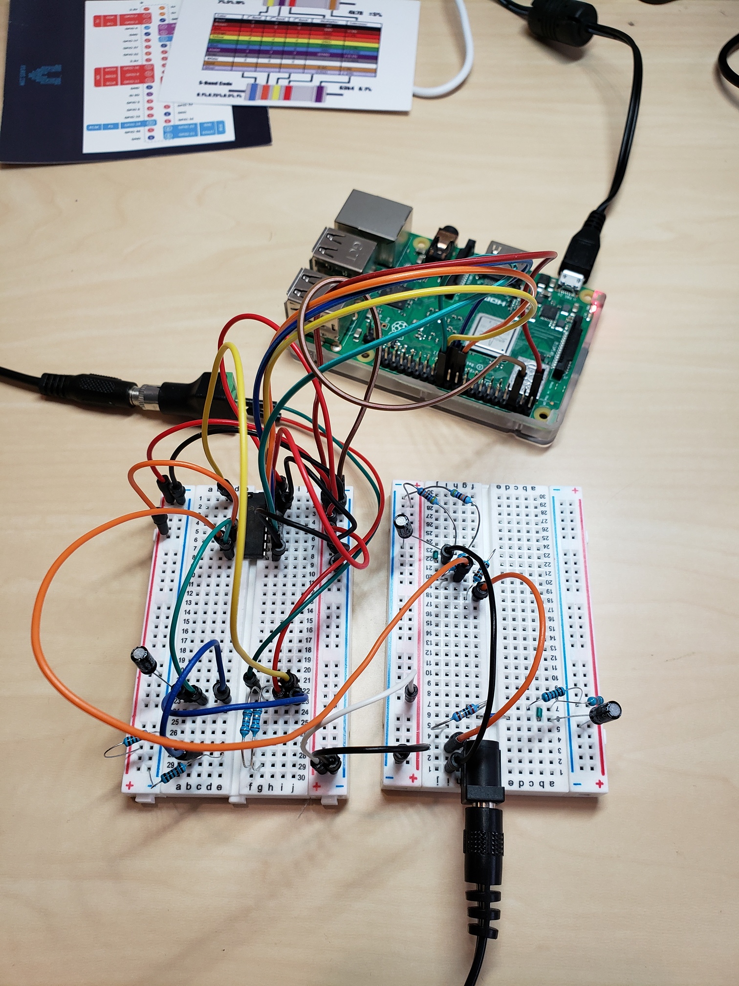
Here it is, in all its ugly glory!
I’m doing the exact opposite of that with my current setup (not intentionally… that’s just how it worked out with my components). ![]()
I’ll work on this now to see if it makes an improvement. I’ll also get rid of the long/loopy jumpers and replace them with shorter flat jumpers, and I’ll snip the extra long leads off the resistors and capacitors so they are more snug on the breadboard. I have a T-style header breakout for my RPI, but it has rather long ribbon cable used to connect it between the board and the breakout. Should I try with that instead of the individual jumper wires between the Pi and the board?
What say you about something like this? I doubt I could fit my project on this single board, but I believe they can be stacked. I like how compact this is. I have not purchased any proto-boards - I’m still looking for the best solution for me.
Thank you Bill! It was only a few months ago that I was playing with LEDs and resistors for the first time. I really enjoy stuff like this, and I wouldn’t be this far in without the help I’ve received from you two. So thanks again!!
![]()
![]()
Hey, just callin’ it like I see it.
You’re one sharp guy, my friend.
And your willingness to help those who want to learn is a rare find these days.
OK, I better stop before you outgrow your present abode. ![]()
That’s something a bit like I thought you’d have. Only worse, if I’m honest. It really does explain everything.
That Adafruit board looks a good bet, or I spotted this, which appears to be the best of both worlds:
https://shop.4tronix.co.uk/products/prototyping-board-kit-for-40-pin-raspberry-pi
The idea is you get it right using the plugboard, then move the components onto the permanent soldered p.c.b. when you’re happy with it.
I’ve not used either, so I can’t vouch for them.
The cables to the RPi will be less important, but you still want to keep them short. If you
Seconded.
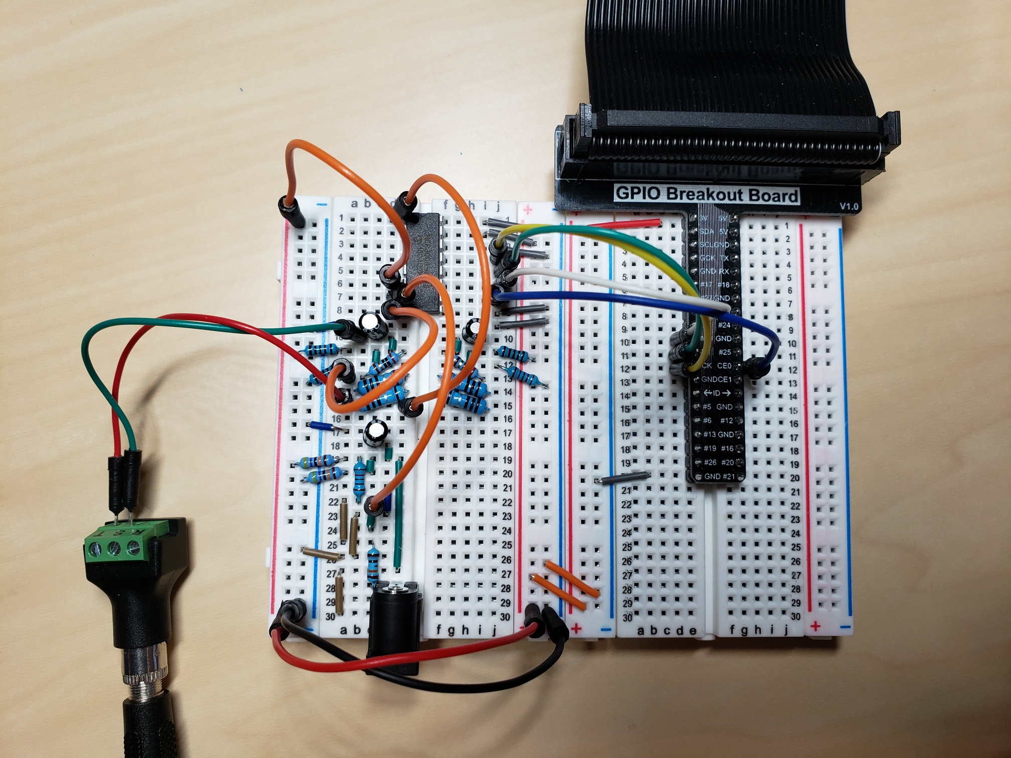
Haha! I’m sure it is common for beginners. I’ve cleaned it up on a new board and I was actually able to condense everything down quite a bit. I was able to condense the circuit for a CT sensor down to 6 rows (rows 9-15 in the circuit pictured below - the left hand side). The circuit for the AC input begins in row 17 and continues to 30. The right half of the board on the left has the circuit for a second CT sensor which I haven’t connected yet. It looks like there is enough space in rows 16-30 on the right half of the left board to build out 2 more CT sensor circuits so I should be able to fit all my inputs on a single 30-row board. The orange jumpers are my ADC inputs.
I grounded nearly (but not all) of the unused rows on the left hand side of the board. The 0.3A RMS current with the CT sensor disconnected still remains. I’ll still have to figure out where it’s coming from, or choose to set a “zero-threshold” to ignore values that fall between a range. I am not worried about the 0.3A discrepancy with regards to the house mains, but for the solar mains, it might have an impact.
I’m not too sure how to go about this… I think I have an idea, but I don’t want to risk damaging any components if I set it up improperly. I’m not too sure about the second 100 nF cap next to the ADC power pins though. Would the 2nd 100nF cap go between the 2 power pins on the ADC, like this?
Edit: I did some research and believe I’ve figured it out. Does this look correct? Not sure where to put the 2nd ceramic capacitor, though.
Adding the decoupling capacitors did not have an effect on the 0.29A RMS current that’s being detected/calculated with completely de-energized conductor. If I remove the input jumper for the CT sensor, the RMS current is still being calculated at 0.29A, so the interference is coming from elsewhere in the circuit.
Cool - I may try the Adafruit board then. The one that you found looks oddly familiar… I looked through my box of parts and found a nearly identical one, but for an Arduino. Maybe I’ll get both! You can never have too many components!
Thank you sir!
I’ve got one of the Adafruit boards on my “radio hub” pi. They’re a good quality board with convenient labels and a layout that makes it very easy to transfer a circuit from a breadboard.
Thanks for your input! I went ahead and ordered a few.
Your ADC is a MCP3008?
If you haven’t done so already, read this: http://ww1.microchip.com/downloads/en/Appnotes/00688b.pdf
OK, you’re not making a p.c.b, but there is a lot of good info in there. Microchip do know what they’re talking about.
Note they recommend 1 µF, not 0.1 µF. I’d go along with that. It won’t hurt to leave the 0.1 µF there as well, in parallel.
According to me, the DGND (digital ground) is pin 9 and VDD is pin 16, so those are the pins that have the 1 µF across them. I think from your photo that VREF is also directly connected to the 3.3 V. That’s likely to be full of digital noise. You need to use a small inductor in series to block the noise coming in that way, again with a 1 µF to decouple the pin, this time to the analog ground. You need to keep the analog ground and digital ground separate, as far as possible. All the analog circuitry needs to come together and be connected to the analog ground, with only one connection to the digital ground, ideally at that 220 µF capacitor, which needs to be where the 3.3. V first comes onto your board from wherever the power comes from. As you have it, the current supplying the ADC ( = full of digital noise) passes along those bus bars to which all the analogue grounds are connected. You need to take the power for the ADC directly from the breakout board and only have the analog ground connected to the bus bar.
It wouldn’t do any harm to twist those wires to the c.t. socket together.
If you have them available, I’d put a 1 µF at each end of each of those power supply busses, in addition to the one as close to the ADC pins 9 & 16 as you can get it.
It’s quite normal to read a fairly high noise value when you’re looking at the rms value, because the random noise is rectified by the squaring process in the rms maths, so the positive and negative values of noise can’t cancel each other out. When you move to real power, the noise should be much lower.
Yes, thank you for the link! I don’t have any disc capacitors that are 1µF - only electrolytic. I was doing some additional reading about MCP3008 noise on the RPi3 and the discussion I found suggested not to use electrolytic capacitors because they have inductive properties due to the way they’re made. I can get some ceramic caps if it’s recommended, though.
Yes, that was the case in the initial picture on a separate, unenergized breadboard. I did further reading and corrected it, then replaced the picture above just a few minutes before you replied, and I think the timing worked out so you didn’t see the new picture.
I’ll have to redo my grounds. Right now everything goes through the bus bar. I will try taking the Dgnd directly to one of the Pi’s ground pin and leave the bus bar for the analog ground (which will go to a separate ground pin on the Pi).
Done!
The real power reading seems to be spot on - where the noise levels are between -1 and +1 W. Since the real power is accurate, I could do something like the following to account for noise on an empty line, but I’m hesitant to do any sort of “cheating”:
if real_power > -1 and real_power < 1:
    real_power = 0
    if rms_current <= 0.3:
        rms_current = 0
… so that the RMS current will read 0 only if the real power is essentially 0. In fact, I’ve tested the above, and it’s not that great when the real power is low, like around 25W or so. The RMS current is still artificially inflated by ~0.29A with such a small load. The tuning I’ve done fixed up the accuracy for larger loads, around 700 - 1300W.
While the above cheat-method might work for the house mains where the current will most likely never be < 1A, it won’t really work for my solar main due to the gradual rise from 0W to peak, and back down again. Real power is fairly accurate, but I’m intending on storing all metrics including RMS voltage and RMS current, so I’m striving for accuracy. As described in the paragraph above, the RMS current on the solar main won’t be accurate for small loads (probably from 0-100W+) until I can improve the noisy CT input. I’m still waiting a few more days for the additional CT sensors to arrive, so I will wait until the weekend to revisit the noise problem once I have the other CT sensors connected to the board.
I’ve also began thinking about my data storage mechanism. I’ve read the Time Series section of the guide and wow, what a journey you guys have had! My implementation will have some small averaging of the raw data before putting it in the database (otherwise I’d be looking at 31.1M rows per year), and I’m currently investigating disk space requirements for different averaging intervals.
Indeed - that’s why most people use the two in parallel - the smaller disc ceramic deals with the high frequencies where the capacitor’s inductance reduces its effectiveness.
Maybe a good reason to look at InfluxDB and Grafana.
You can set retention policies to keep your database from growing past a specified point, as well
as downsample the long term data. (Paul Reed does that, see this thread: Grafana Dashboard Project)
Grafana has the ability to display data smoothed via a moving average.
In fact, you can actually do a fair amount of math right in Grafana.
Food for thought…
Thanks for the recommendation, Bill. I was planning on using SQLite and Grafana for my backend/frontend. I’m not that familiar with InfluxDB but at first glance it seems to be a solid candidate for the job.
I’ve never used Grafana before - historically speaking, I’ve used matplotlib and Plotly for my charting and reporting needs in other projects. But my research into Grafana has shown me it’s so much more than that! Thanks for the link to Paul’s thread.
Odd coincidence that you mention SQLite, as that’s the database Grafana uses to store its internal
configuration.
I run both, (Influx and Grafana) as does Paul, and there may well be other users here who do too.
I can think of at least one user who runs Influx but uses a different graphing app.
I’m willing to help with both apps when and where I can.
Both apps have active forums with helpful users, so support shouldn’t be too much of an issue.
We’re here to help.
Thanks Bill! SQLite was my initial go-to for this project since I am going to try to run everything on the Pi 3B+, and SQLite is fairly lightweight as I’m sure you know. It looks like InfluxDB requires a server process like other DB engines, but I will give it a try because I’m interested in learning first-hand about the benefits it offers as a time-series database.
If I run into performance issues on the Pi I may have to move to SQLite, upgrade to the Pi 4, or do the data collection and monitoring on another system (like my QNAP NAS) and just probe the Pi for raw data. I had originally wanted to use the Pi Zero W, but I’ve already ran into performance issues just with the raw SPI data collection on that system. Looks like I have plenty of options to get started!
Although that’s true, Influx/Grafana performance is reasonable on a Pi 2, and as you would expect,
even better on a Pi 3. I haven’t bit the bullet and bought a Pi 4 yet, but I can’t imagine the performance
not being good on a “4.”
Not sure what you mean, but both Influx and Grafana are their own servers, and both are single file executables.
You should be OK. I ran both on a Pi 2 for about two years and never had an issue.
That’s understandable, as the Pi Zero is essentially a Pi 1 running at 1 GHz vice the 700 MHz
the original Pi 1 ran at. On top of that, the CPU is a single core device. RPi 2, 3, and 4 all have
multi-core CPUs, as well as faster clock speeds.

