DIY Current Monitor on Raspberry Pi. My power calculation isn't accurate. Help please?

That’s good news for my 3B+! Just curious, why would you not expect performance to be good on a 4?

I was comparing SQLite to Influx on the basis that SQLite does not require a server process to interact with the database, whereas Influx and other DBMSes do. I was just trying to suggest that Influx will have that much more overhead… however much that is, I don’t know, and it probably won’t matter too much.

I was admittedly over-optimistic about the Zero’s capabilities, while at the same time not understanding all the complexities I was facing as I opted to venture out on this project. I’m not opposed to buying a Pi4 for it, but I’ll try to stretch the 3B+ a lot further than I did with the Zero.

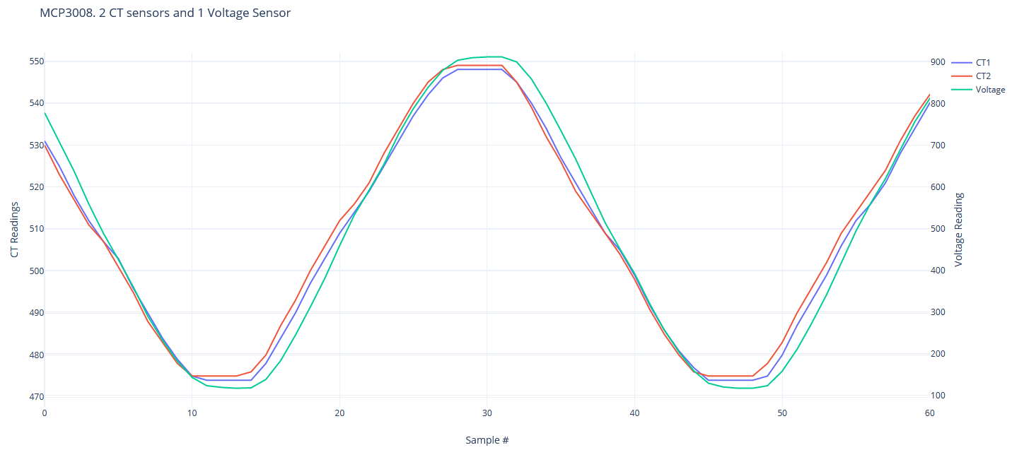
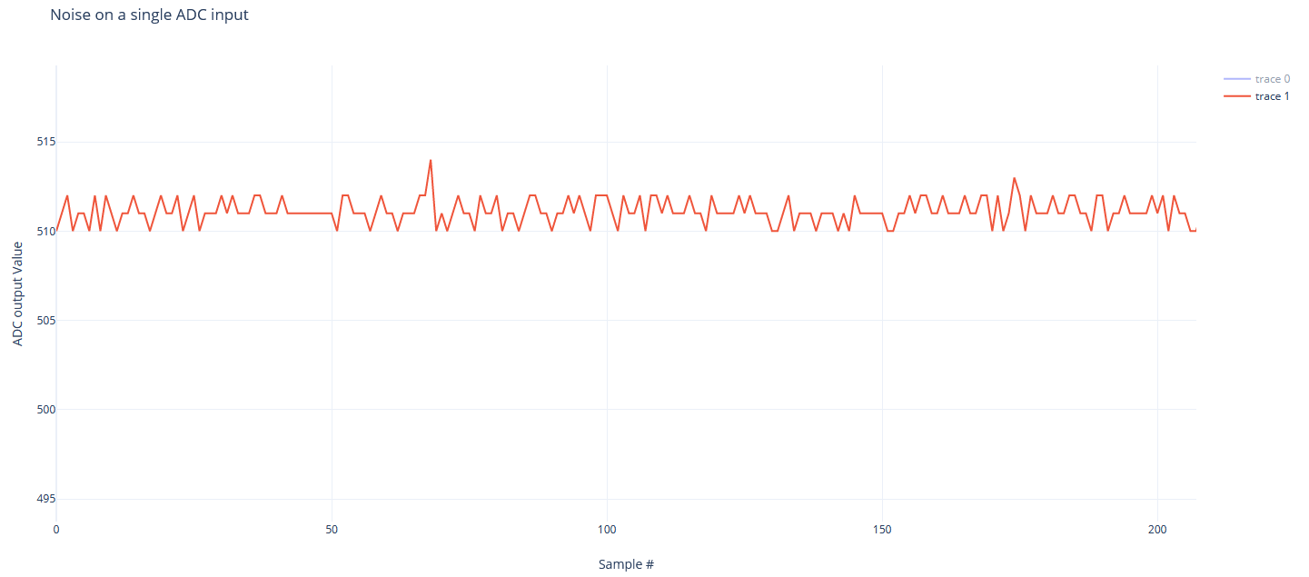
On another note, I believe I’ve resolved the source of the “noise”. Turns out it was a programming error! :man_facepalming:

I walked through my code step by step to see why the RMS current seemed to be calculated at a static value of 0.29A. I dumped the raw data from the ADC and took a look at it - my circuit’s “zero” (or “reference”) level is 511, and I was using 512 in my calculations. So, for a single poll cycle of 2000 data points, my sum_squared_current variable was about 2000, leaving an RMS current value of sqrt(2000), times my current scaling factor and tuning correction, for a final, RMS current approximation of 0.29A. Now that I’ve corrected that, it is looking much better:

Real Power: 0.018 W | RMS Voltage: 121.878V | RMS Current: 0.011A | Apparent Power: 1.369 W | Power Factor: 0.013
Real Power: -0.022 W | RMS Voltage: 121.874V | RMS Current: 0.014A | Apparent Power: 1.767 W | Power Factor: -0.013
Real Power: -0.047 W | RMS Voltage: 121.914V | RMS Current: 0.013A | Apparent Power: 1.581 W | Power Factor: -0.03
Real Power: -0.016 W | RMS Voltage: 121.867V | RMS Current: 0.017A | Apparent Power: 2.091 W | Power Factor: -0.008
Real Power: 0.095 W | RMS Voltage: 121.854V | RMS Current: 0.018A | Apparent Power: 2.235 W | Power Factor: 0.043

The output above is from a CT sensor that is surrounding a non-energized conductor. I’m not sure why some real power values are negative, but I would guess it’s because I have a small uncorrected phase error between the voltage reading and the CT sensor in use.

I really appreciate everyone’s input, time, and dedication to helping me through this project so far. I’m almost there!

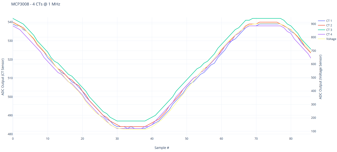
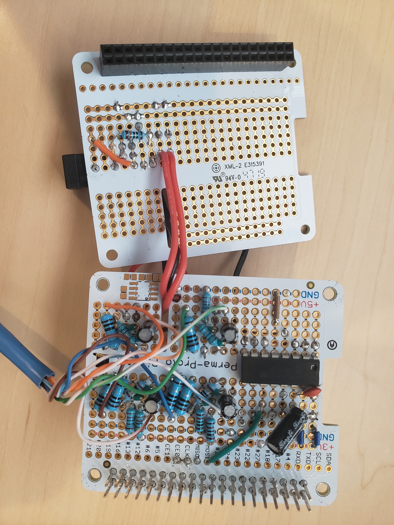
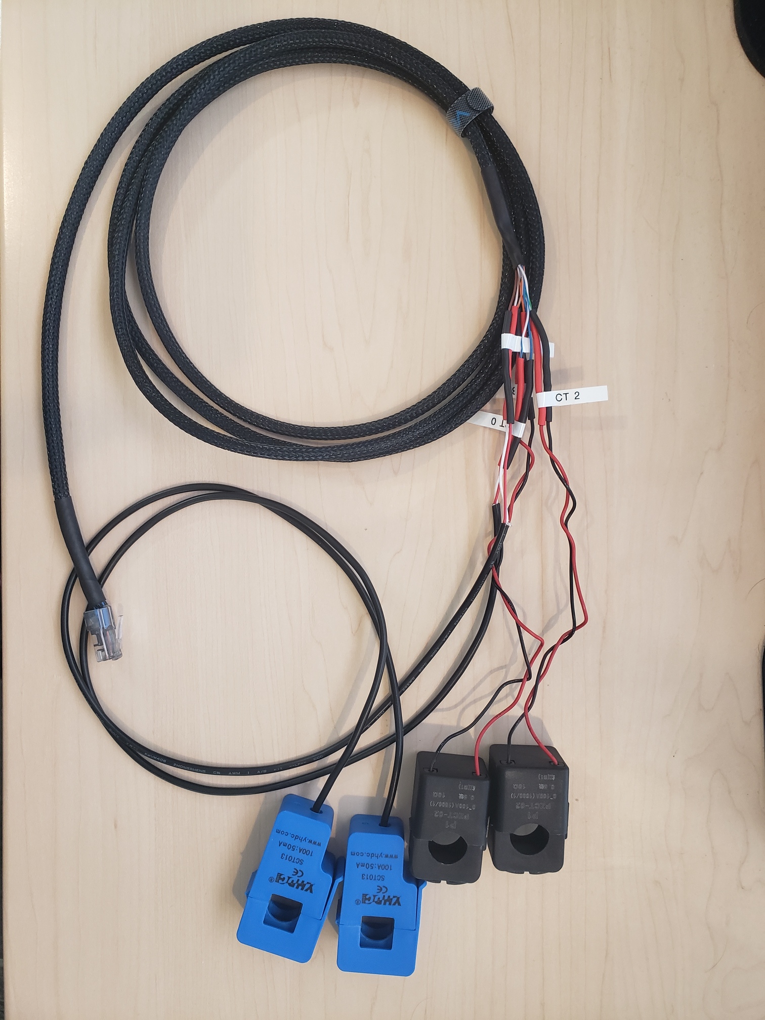
Next steps will be to wire up the other 3 CT sensors on the breadboard and connect them to the mains so I can start working on the software. Once I’m confident that my circuitry is solid and have some momentum with the backend programming I’ll transition the project to the prototype boards.

I think you misunderstood me…

There’s a double negative there. :wink:

You should be good to go with a 3B+
I noticed an improvement in performance when I went from a Pi 2 to a Pi 3.

highfive thumbsup

Keep hammer_hitting_head ing on it! beer_cheer

2 Likes

Do you mean you’re using a fixed value to remove the offset imposed by the need to apply an offset voltage to the ADC input?

If yes, that’s a seriously bad idea because drift in the component values can make it shift over time, so your problem may creep back and you’ll not notice it. Provided that the offset is not changing too quickly, i.e. not discernibly within the averaging period of your measurements, it’s much better to calculate the average and then subtract the power/current/voltage that represents. (Or if you’re worried about the size of the numbers, subtract the fixed ‘512’ just to get close and then calculate the average to trim the values accurately.)
True power = calculated average power - (offset voltage × offset current)
True rms current = √([calculated average of current²] - [average current]²)

1 Like

Doh!

Yes.

This makes total sense now! When you had mentioned it last time, I wasn’t too sure about it. After my testing last night and inspecting the raw data, I was using the average from 10 sample sets (20k samples) to find the reference value in both the voltage and current sensing circuits. I’ll make the change this evening. Thanks Robert!

Also, I do intend on releasing my code when I have something working. I want to contribute to the project and maintain the ethos, and sharing my project is the best way I can think of.

1 Like

Robert, I’ve been thinking more about optimization since I removed the static 512 “reference” variable from my calculations, and I have come across a couple of points I wanted to ask you about.

First off, it would be nice to remove all static values from my calculations, but I can’t seem to come up with a way to get rid of the static value I’m using in my scaling factor calculation. The static value is 3.31 (as previously measured with a multimeter) for the voltage of my board. I currently take 10 readings from the board (via a channel on my ADC), and I multiply the average reading by a constant 3.31 to get the approximate board voltage, ie:

samples = []
    while len(samples) <= 10:
        data = readadc(board_voltage_channel)
        samples.append(data)
    avg_reading = sum(samples) / len(samples)
    board_voltage = (avg_reading / 1024) * 3.31

Later on in the execution of my program, I use the board_voltage in the scaling factor calculation:

current_scaling_factor = (board_voltage / 1024) * 100 * (1 + CT_accuracy_factor)
voltage_scaling_factor = (board_voltage / 1024) * 126.5 * (1 + AC_voltage_accuracy_factor)
total_scaling_factor = current_scaling_factor * voltage_scaling_factor

My efforts in finding a way to remove this constant have led me to believe there has to be an assumption somewhere in the code, otherwise we can’t turn the ADC output into meaningful data.


My next question is about the phase correct algorithm. Dealing with such small timescales, the order at which voltage and current are sampled will affect the outcome. I was just experimenting with this idea by changing the order in which voltage, CT1, and CT2 are being read.

My 2 CT sensors are on the same conductor about 10cm apart from one another. Out of curiosity, I tried to “sync” the CT sensor readings by removing a single sample from the head of one CT data set (and removing the tail on the other to keep the data sets the same length). This was too large of a correction and increased the phase difference between the two sets.

The question is - can the phase correction algorithm be applied to different sensors to correct for the timing difference at which they are read? Or, is calibrating at this level likely not necessary? Here is a data sample of my voltage, CT1 and CT2 readings, where the order of collection is voltage, CT1, CT2:

Also, it looks like I’m only getting about 35 samples per 60Hz period, per channel, with 3 channels currently being read. That’s about 2100 SPS per channel - or about 6300 SPS for the ADC. When my other 2 CT sensors are in use, the per-channel rate will go down. Earlier in this thread (post #11), you had mentioned that EmonLib gets about 44 sample pairs per cycle. Is a pair, in this context, 1 CT reading + 1 voltage reading? I just want to ensure I don’t fall too far below what the project has already established as fast enough sampling.

I suspect I’m hitting the limitations of the Pi’s clock speed because the MCP3008 has a max sampling speed of up to 75 KSPS at 2.7V. I’m running the chip at 3.3V so in theory, the ADC should be able to hit sample speeds near this threshold, assuming a device can request data from it at that speed? This reminds me of a saying my flight instructor would say: “In theory, practice and theory are the same. In practice, they aren’t.”

Somewhere, you need a way to tell the code the relationship between ADC counts and the reference voltage. Usually, the maximum count represents the reference voltage. Either you can hard code what you think it should be - meaning that any error in it gets added to the general calibration error, or you can measure it and type it in as a calibration variable, or if you have an internal reference of sufficient accuracy that it can measure against its own reference, then you can derive the actual calibration from that. You must have one of those, there’s no escaping it.

What is board_voltage_channel actually measuring?

Yes, that’s correct.

It can. The total error you’re trying to remove has 3 components - the time between readings, the phase error of the v.t. and the phase error of the c.t. The two transformers are likely to be different. If they’re different by exactly the time difference (converted to degrees), get them in the right order and no correction is needed. Otherwise, and most likely, you should choose the order so that the minimum correction and preferably always interpolation (i.e. the correction constant is between 0 and 1) is needed.

EmonLibCM does things differently and more like the way you’re doing it. That does one sample every 104 µs, so for you with 3 samples per set now, and later 5, that would do 53 or 32 sample sets per cycle. The library will actually take 1 voltage and 5 current inputs (all the analogue inputs of the '328P) and that’s really on the bottom limit of acceptable, especially on a 60 Hz system.

Or the SPI - which is (apparently) tweakable.

Hmm. I’m a lapsed private pilot.

1 Like

board_voltage_channel is just an integer representing the ADC output channel. readadc() is the function that returns a single reading from the channel passed to it.

Since my last reply, I’ve been busy incorporating the remaining 2 CT sensors on the board. I also increased the MCP clock speed to 1 MHz where I can now read about 95 samples per 60Hz cycle, or about 4588 SPS, per channel, for a total rate of 22.9K SPS (5 channels total). The Pi is handling the processing of the data flawlessly.

Here is how the data looks from all 4 CTs and the voltage sensor with a ADC clock speed of 1MHz.

Anything over a 1 MHz clock speed on the ADC yields inaccurate data which appears to not be of concern since I’m able to achieve a fairly high sample-per-cycle rate. Now I have first hand experience of why the original ADS 1115/1105 chip that I started with is not fast enough!

I was totally incorrect on my suspicion. I had mistaken the Python spidev’s library max_speed_hz attribute for the max sample speed possible. The MCP3008 ADC reportedly has a max sample rate of 200k SPS when run @ 5V (slower, if run at 3.3), and I made the assumption that setting the max_speed_hz attribute was the same as setting the sample rate. When I incorrectly suspected I was hitting the limitations of the Pi’s clock speed, I was under the assumption that it wouldn’t make a difference if I set the max_speed_hz variable higher than 200k. Boy was I wrong!

Very cool! I am a private pilot as well (though I am fully current) :smiley:

I am preparing to move my project to the Adafruit Perma-Proto boards I purchased - unfortunately, all but one of the 5 individual circuits fit on a single Perma-Proto board. I’m going to have to either stack two boards and deal with wiring the ADC input from the top board to the bottom board, or come up with a different prototype board solution. I feel that my circuits are already as small as I can get them, with a single CT circuit taking up 6 rows, and the voltage sensor taking up 9 rows (with a female DC jack).

1 Like

Is it worth your time to grab KiCad/Eagle/Fritzing and design your own Pi “Hat” PCB?
You can get PCB’s made in small quantities quite cheaply these days, most place offer very cheap rates for “first time buyers”.

JLCPCB get the thumbs up from the creator of the Great Scott YouTube channel.
image

Look at the DIYBMS threads for more details of custom PCB manufacturers.

Thank you guys. It may be worth investing the time into custom designing a PCB for my needs. I’ll do some research, but I’m sure this is another huge rabbit hole I’m about to jump into!

Well, I finally finished copying my project to a protoboard and I’m not getting any ADC readings on any of the channels. I think the most likely issue is a bad ADC. I spot checked a few places on the protoboard and the voltages seem correct (I’m getting 1.65V where I should be, etc). It will take me a considerable amount of time to remove the ADC and try another one - I can’t find my solder wick and I don’t think the solder sucker will be much help. I may not even bother with it unless my curiosity gets the best of me.

At this point I can either re-attempt copying the project to a different protoboard or start looking into PCB design fundamentals. Are there any tools that assist in going from a circuit diagram to a PCB design, or will I have to setup layers, place components, and route traces manually?

Edit: After reviewing my failed protoboard attempt to look for things that could have gone wrong, I realized I didn’t even connect the ADC clock, Din, & Dout! :man_facepalming: :man_facepalming: :man_facepalming:

That’s a bummer.
But it sounds as if you’re not letting it slow ya down! thumbsup thumbs_up

I learned the value of a good IC socket the hard way too. :wink:
I use this type:
image
as opposed to this type:
image
The pins are stouter, and the sockets better. (they’re very similar to a MIL-spec component)

2 Likes

So yer rockin’ and rollin’?

So far so good! I still have two more CT sensors to wire in tomorrow, but I’ve successfully tested the AC voltage input and 2 out of 4 CT circuits. I’ll get the other CT sensors connected tomorrow so I can test the circuitry. Assuming that’s good, I’ll have to do some more tuning, and then after that, I’m hoping to start on the database implementation!

1 Like

Good to hear!
Dont ya just love it when things start to fall into place? :grin:

I sure do! And now that everything is together, I’m having some signal noise problems.

I soldered the leads from each of my CT sensors to a pair of wires in a UTP cat5e cable since I didn’t have any shielded on hand. I put an RJ-45 on the end of this cable, and soldered in another cat5e cable to the board, with an RJ-45 on the end of this side. Then, I am connecting the CT leads to the lead off the board with an RJ-45 coupler:


The top board in the picture above is the single circuit for the AC transformer input. The board below has the circuitry for the 4 CTs and the ADC:

Here’s my CT sensor cable:

The noise on any given CT input looks like the following. This data was captured with the CT leads connected to the board via the coupler:

If I remove the leads, the noise is much better, like so:

Should I try using shielded twisted pair? Or try without the coupler in between the board and the CT sensors? Or does the proto-board look like a total hack job and I should instead go with a custom PCB? :smile:

What is the “noise current” when you take the rms value and put is as a percentage of full scale input? That’s the value that interests you the most. I’m no expert at guessing rms values of noise, but to me, I’d say its around ½ % of full scale. Bear in mind that it will be much less significant when you do the real power calculation.

I certainly wouldn’t condemn the proto-board out of hand when you’ve got ±1 count of pickup/noise, in 500.

It would be worth checking the noise/pickup with a c.t. just on its own leads. If it’s much the same, screened cable won’t do you much good (though done properly, it will always help).

The RMS current on each channel is usually between 0.5A and 1.1A. I averaged each CT sensor’s RMS current value over about 30 seconds and the average of the RMS currents for each sensor are:
Averages: Ct0: 0.63 | Ct1: 0.63 | Ct2: 0.67 | Ct3: 0.64

All CT sensors are marked at 100A current sensors, so the percentage that the noise represents is about 0.65%

That’s with my cat5e CT sensor bundle connected with the coupler. If I remove the cat5e CT sensor bundle (so that I only have the short cat5e pigtail with the RJ-45 coming off of it, like in the first picture of my previous post), the RMS current on each CT sensor channel is about 0.2. The averages of several RMS current readings from each sensor in this configuration are:
Averages: Ct0: 0.21 | Ct1: 0.21 | Ct2: 0.21 | Ct3: 0.22
So without the CT sensor leads connected, the noise represents about 0.21%

With the CT sensors connected to the board, but not surrounding a conductor, the real power is being calculated anywhere from -1.5 to 10+ W on each CT lead.

I see what you’re saying. The +/- 1 (or 2) with the CT leads disconnected tells me that the circuitry on the board isn’t all that noisy.

With the CT leads connected to the board, the error spread becomes much bigger - about +/- 22. The minimum “noise” is about 470 and the maximum noise is about 515.

So your problem really is pickup rather than noise per se coming in via the power supply or random noise in the electronics.

What is the value of the decoupling capacitor on your mid-point bias (C1 in the diagram on Post no. 15) and what type is it?

My second thought is, if you’ve copied that circuit (or rather, its equivalent for the c.t.) exactly, you don’t have an anti-alias filter on your inputs. Apart from reducing the input bandwidth to prevent aliasing, that would also tend to filter out any high frequency radiated signals that the c.t.'s and their leads are acting as aerials for. If you have handy a small value capacitor - say 10 - 47 nF, you could try that from the ADC input to GND and see what effect it has. If it’s radio frequency (or radiated from switched mode power supply), then that should damp it down somewhat.