ADS1115 and sampling speed

I’m experimenting with Wemos D1 Mini and using it to read from two CT sensors.

I just realized that by nature the sampling algorithm is kind of slow. I was able to change the ADS1015 rate to 3200/s and change its default read delay from 8 to 4ms, but the library still needs a fair amount of time to go through the 1480 samples.

The reason why it is a problem for me is that I also have a photo resistor on pin 0 of the ADS1015, that photo resistor is used to catch a laser light that is going through the hole in the meter disc. I’m basically counting rotations with it.

But for this to work, I need to be able to poll the photo resistor value much more often than what I can do now (I get a value every 2 or 3 seconds, way too much to “catch” the light going through.

Any idea to make things more parallel, would that be a problem if I probe the photo resistor level into the calcIrms() loop?

Thanks!
The idea behind 1480 samples was, it was a whole number of mains cycles for either a 50 Hz or 60 Hz system, and gave a reasonable number of cycles over which to average the current so that any “end effect” of an incomplete cycle wouldn’t introduce to large an error in the rms calculation.

So you need to see how many samples you measure per mains cycle, then decide how many cycles you’d like (emonTx ‘discrete sample’ sketch does 10, but when measuring voltage it knows where a cycle starts - I’d suggest 20 cycles) and calculate the appropriate number of samples to replace the 1480.

Would half a second or thereabouts (20 cycles) be fast enough?

Otherwise, yes, you can of course check between samples - but that will mean you do not measure the waveform as accurately, and if you check between batches of samples, you will sample at irregular intervals and the answer will be inaccurate again.

In the emonTx, this type of problem is solved by having the pulse trigger an interrupt, and provided the interrupt routine does very little, it doesn’t materially affect the timing.

I cannot see a mention of a 4 ms or 8 ms delay in the data sheet - what is that?

1 Like

Thanks again Robert

I cannot see a mention of a 4 ms or 8 ms delay in the data sheet - what is that?

Apparently, I got myself a ADS1115, which has 16bit resolution but can only sample 860/s. Kind of a bummer for what I’m doing here, I should have bought the ADS1015 which has 12bit resolution, but 3600/s.

In fact, my PCB doesn’t even say which one it it, probably because it’s a common for both chips.

In the header file Adafruit_ADS1015.h, you can see this :

    #define ADS1015_CONVERSIONDELAY         (1)
    #define ADS1115_CONVERSIONDELAY         (8)

I assumed it was to accommodate the max 860SPS, but actually it doesn’t make much sense. I’m still trying to find the explanation to this.

In the meantime, I’m working on the code for the higher resolution, and not sure I got it right.

Basically, with nothing plugged on the CT input, I get the following values :

Irms = 20.581
ADS = 12976

12976 is relative to a full scale of 32767 for 0.125mV per step with the gain I use :

//                                                                ADS1015  ADS1115
//                                                                -------  -------
// ads.setGain(GAIN_ONE);        // 1x gain   +/- 4.096V  1 bit = 2mV      0.125mV

Which is basically 1.6V (half the 3.3…) It seems normal to me but look at the samples I get when I attach the CT :

1 : 13170
1 : 12830
1 : 13100
1 : 13028
1 : 12856
1 : 13136
1 : 12806
1 : 13171
1 : 12782
1 : 13179
1 : 12782
1 : 13166
1 : 12815
1 : 13117
1 : 12890
1 : 12967
1 : 13090
1 : 12831
1 : 13151
1 : 12792
Irms = 20.59

Looks kinda crappy to me :-/ That’s with 20 samples, and Irms should be around 2 or 3 Amps

At that point I’m trying to figure out if something is wrong with my circuits or with my tweaks in the software.

By the way, the burden is 33Ω and the calibration value 60.60

Now I know why 1480 samples was taking a long time, at 14 samples per cycle!

The quick answer is you’ll have to crawl through the library routine, checking that you have all the right values everywhere, and calculate your calibration constant, most likely from first principles.
The long answer will have to wait until tomorrow - or later.

I’ll keep digging yes, I start to have some sort of grasp of what the library is doing, I might be able to figure out why the calculation is off. I have the same system running on the Uno, I can compare the voltage and other values I get. Thanks!

One thing I just found out : ADS1X15 do not use the input V as a reference for the scale, they use fixed values.
In my case, with GAIN=1, it measure +/-4.096V.

Now, I’m not sure but I think just changing SupplyVoltage in the function won’t be enough here :

  #if defined emonTxV3
    int SupplyVoltage=3300;
  #elif defined(EMON_ADS1X15)
    int SupplyVoltage=4096;
  #else
    int SupplyVoltage = readVcc();
  #endif

I think there is an additional relation to establish with the calibration, but in the docs I saw calibration was always explained based on the circuit voltage, not specifically the voltage used as a reference for the analog converter.

I will try to scale the measurement en present values relative to 3.3 tot he algorithm and see how it goes

Encouraging results : applying a factor 4096/3300 to sampled values get me to

Irms = 1.6 when nothing is connected
Irms = 99 when sending 3.3V or GND

1.6 is still way to high, and it doesn’t seem like measuring an actual CT makes much of a difference.

But as my head is about to explode, that will be for another day!

#ifdef EMON_ADS1X15
sampleI = ads.readADC_SingleEnded(inPinI)*4096/3300;
#else
sampleI = analogRead(inPinI);                 //Read in raw current signal
#endif

Explanation for the 8ms delay :

https://forums.adafruit.com/viewtopic.php?f=25&t=50446

Those are derived values.

The ADS1x15 family of ADCs have an ALERT/READY pin that generates a pulse when each conversion is complete, but using that consumes a microcontroller pin and an interrupt service routine. Instead of using that, we wrote the library to wait for a fixed amount of time for the conversion to finish.

The ADS1015’s maximum sampling rate is 3ksps, so a 1ms delay (corresponding to a rate of 1ksps) strikes a balance between simplicity and guaranteed success of getting a conversion. The ADS1115 can do 860sps, and our default delay takes the rate to 125sps.

So I need to change the SPS to the max 860 and reduce this to 1ms

Ok the speed problem is now solved, the Adafruit library needs some serious work, I suggest people use GitHub - jrowberg/i2cdevlib: I2C device library collection for AVR/Arduino or other C++-based MCUs instead, it’ll let you adjust reading speed easily and has no constant delay implemented.

The relevant code is below in EmonLib.cpp's EnergyMonitor::calcIrms

  for (unsigned int n = 0; n < Number_of_Samples; n++)
  {
    #ifdef EMON_ADS1115
    sampleI = ads.getConversion(true)*4096/3300;
    #else
    sampleI = analogRead(inPinI);                 //Read in raw current signal
    #endif

    // Digital low pass filter extracts the 2.5 V or 1.65 V dc offset,
    //  then subtract this - signal is now centered on 0 counts.
    //offsetI = (offsetI + (sampleI-offsetI)/1024);
    offsetI = (offsetI + (sampleI-offsetI)/1024);
    filteredI = sampleI - offsetI;

    // Root-mean-square method current
    // 1) square current values
    sqI = filteredI * filteredI;
    // 2) sum
    sumI += sqI;
  }

  ICAL=1;
  double I_RATIO = ICAL * ((SupplyVoltage/1000.0) / (ADC_COUNTS*4096/3300));

  Irms = I_RATIO * sqrt(sumI / Number_of_Samples);

  //Reset accumulators
  sumI = 0;
  //--------------------------------------------------------------------------------------

  return Irms;

Here sampleI is pretty steady between 16107 and 16110, which is 1622 mV.

Running the code by disabling ICAL(set it to 1) I get Irms = 0.01 Beautiful!

Now I need to continue and start the tests with the CT connected.

As you are measuring only 14 samples per cycle, you might need a different constant (not 1/1024) in the filter to maintain roughly the same time constant in seconds - or you might find that the ripple is more noticeable with the higher resolution of your ADC, so the original value remains sensible because it will give a (roughly) 8 times longer physical time constant which more than compensates for the increase in ADC resolution.

If you’re not switching the CT input from zero to half-scale (by plugging in a CT as is done with the emonTx V3), then you can have a much longer settling time because the d.c. bias should never move quickly, if at all. The only reason for the filter to adjust the offset quickly will be at start-up if the d.c. bias is not exactly mid-rail but the filter output has been pre-loaded to the ADC mid-point value.

Right now, I’m actually reading 1480 samples in 1032ms. One cycle here is 50Hz, 20ms ? Witch is 28 samples per cycles, but that exceeds the 860 max SPS of the ADS1115, so some values are probably returned twice.

I’m not sure I understand what you suggest (ok, let’s face it, I don’t understand what you suggest :-)).

  • What would be a good replacement for the 1024 constant? 4096 gives me worse values (1.17 Irms) whereas 256 gives me 0.41, better. should I go lower or is this nonsense? Disabling the low pass completely gives me 0.00, even when the CT is plugged with some charge.

With a charge of approx 47W (I know this is really low, I need to put together an extension chord with a meter in the path), I get an Irms of 0.83 (should be 0.37, but with no charge I’m already getting 0.79), the amplitude of the values I read are like this with the CT connected :

low:  15965 (delta 277, 34mV)
high: 16242
Irms = 0.83
low:  15970
high: 16238 (delta 268, 33.5mV)
Irms = 0.83
  • Is the fact that I’m getting some values twice (because of the 860SPS) a problem?
  • I’m still getting 0.79 Irms unplugged, I don’t really understand that, without applying a constant, the Irms is 0.01, probably too much in fact. My raw V reading is 1621mV without the CT, is that the expected value or should I be closer to 1650 (3300/2)?

Thank you!

Nope. 60 Hz, 16.667 ms.

That is the filter’s time constant. That’s a loose term, because it is related to sample rate, not time per se, which is why I suggested it would be wrong. It could also be not right because it also controls the ripple in the output. Ideally, output ripple should be less than one LSB, so that the filter output is always the same number, but that’s probably unrealistic, and a variation of a few counts won’t materially affect the answers. If you make it too large, the filter will have zero ripple but will take too long to settle if the input level shifts. If you make it too small, the filter will respond quickly to a level shift but will also let through more of the 60 Hz that you’re trying to remove.

You need to be sure you’re reading the ADC correctly - you’re wasting time and effort until you get that right.

Why not set up a spreadsheet with the same number of samples per cycle of a sine wave as you’re reading (several cycles), write the filter equation into the sheet and plot the filter output against time (sample number). Then you can see exactly what happens as you add in a step in the input, or change the filter constant.

Great idea, I’ll work on that.

Isn’t it 50Hz in the U.S. ?

What about that Robert?

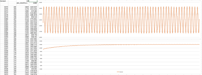
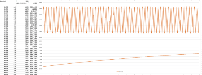
Top is raw values, bottom is filteredI, as in :

sampleI = ads.getConversion(true)*4096/3300; // Apply scale factor from reference 4096mV to 3300 mV
#else
sampleI = analogRead(inPinI);                 //Read in raw current signal
#endif

// Digital low pass filter extracts the 2.5 V or 1.65 V dc offset,
//  then subtract this - signal is now centered on 0 counts.
//offsetI = (offsetI + (sampleI-offsetI)/1024);
offsetI = (offsetI + (sampleI-offsetI)/1024);
filteredI = sampleI - offsetI;

That screenshot represents 1000ms, as you can see, it takes a lot of time to stabilize with 1024

With 128, here is what I get :

Much better.

Tese samples were takes with a load ~1500W

I will do the test again with 128 tonight and see if I can get consistant and reliable values!

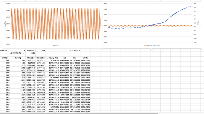
Maybe it makes more sense presented that way, this is millisecond 2000 to 3000

My interpretation is that given the relatively high values of filteredI, the calculations for the calibration value are no longer valid but I fail to understand the logic behind the original 60.60 value, that didn’t take the ADC scale into consideration if I understand the documentation, why changing the scale of the converter require an adjustment of calibration?

Do these results look valid and consistant to you?

No, the North American grid frequency is 60 Hertz.

One of the reasons that we changed from using a high pass filter - to remove the d.c. offset directly and used instead the low pass filter to obtain the value of the offset and then remove it by a simple subtraction (there, that’s answered the questions I set you in your other thread!) was it is very simple to pre-load the filter output at start-up with the expected result. That means that the start-up time of the filter is very short, so you can have a long time constant. The advantage of a long time constant is it removes the ripple, as you can see in your graphs. If you try 1024, but initialise the filter output to the value it is aiming for, you will see a response much more like the “128” graph but with the ripple of the “1024”.

It is related to the CT ratio and the burden resistor value. Because you are now using a totally different ADC, you will need to calculate your calibration from first principles. The steps are roughly: What primary current swing gives you what values swing from the ADC? (This incorporates and so needs knowledge of the CT ratio, the burden value and the ADC reference voltage and resolution.) The calibration constant is then the scale factor that means the maths gives you the correct rms value for the rms value of that primary current.

So I understand now why offsetI is initialized to ADC_COUNT >> 1, which is the binary equivalent of ADC_COUNT / 2.

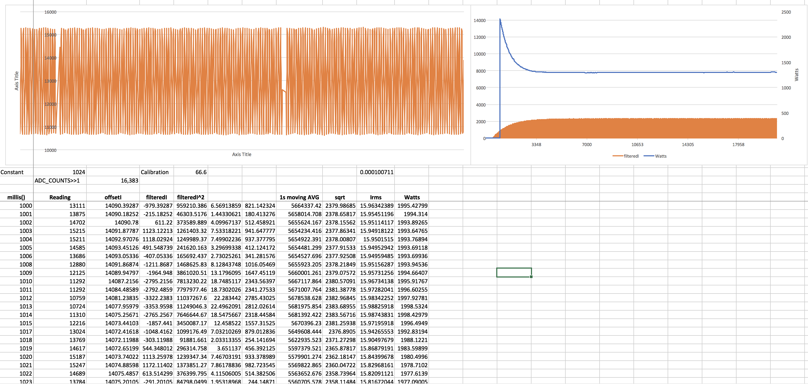
All right, in the end, it means I just have to be patient, and looking at a bigger scale, I actually stabilize after 4s or so with a value of 1024.

I actually fixed the spreadsheet, and calibration is more aligned with “regular” values

My next step is probably to do different load tests and see how it goes.

Thank you Robert

That’s probably not a good thing and warrants further investigation. Which part are you using? The title suggests an ADS1015 but I see references to ADS1115. It looks like the former can do 12-bit samples at 3300 SPS and the latter can do 16-bit conversions at 860 SPS.

I thought of you OEMers the other day. I’m currently using some STM32 processors on a project unrelated to energy monitoring, but when I discovered the phenomenal ADC performance I couldn’t help but think what a great OEM platform it would make. It can do 12-bit conversions in 1 usec, do a continuous sequence of them in the pin-order of your choosing, and load the results directly into your C datastructure, all without any CPU interaction at all. Imagine an interrupt every 1 msec to say “I’ve just loaded those 1,000 12-bit samples you requested into your first array and I’m currently working on filling your second array with a new 1,000 samples”.

2 Likes

Yes I fixed the title earlier, it’s actually a ADS1115, so I’m doing 16bit@860 (actually 15bit as there is one reserved for the sign, as the chip can measure +/- voltage).

Yes, that sounds like a really good fit for what we’re doing! The STM32 seems like a pretty beefy chip though compared to the ESP8266. That’s pretty amazing what you can do today with $10 bucks though.

I think I am getting somewhere though, the waves looks good enough for the precision I need, but I just realized something : when I decided on my burden resistance I did all the calculation with 50mA CT output… but that’s the RMS, I need to do the math with the peak, is that correct?

So instead of 33Ω, I need 23.57 (and whatever is lower as an actual resistor, probably 22Ω, then I will probably get a proper “zero” which is not the case at all now.

After that, I decided to give interrupt a try to detect the laser in front of the meter disc, instead of polling.

That way, I will be able to alternate CT measuring for CT1 and CT2, and setup an interrupt to get the disc spin notification, and I won’t have to worry about the “slow” ADS1115 anymore, as I have nothing else that is time critical.