Current Monitor/Shunt

Ok, I’m finally getting back to this, but still just having nothing but problems programming the shunt.

I have a USBTiny to use as the programmer, and have installed the latest avrdude.

./avrdude -v -C avrdude.conf -p attiny1614 -c usbtiny -U flash:w:diyBMSCurrentMonitor_ATtiny1614.hex:i

But this is what I get in the output:

avrdude: Version 6.99-20220211 (7b79b72)
         Copyright (c) Brian Dean, http://www.bdmicro.com/
         Copyright (c) Joerg Wunsch

         System wide configuration file is "avrdude.conf"
         User configuration file is "/Users/ian/.avrduderc"
         User configuration file does not exist or is not a regular file, skipping

         Using Port                    : usb
         Using Programmer              : usbtiny
avrdude: usbdev_open(): Found USBtinyISP, bus:device: 020:030
         AVR Part                      : ATtiny1614
         RESET disposition             : dedicated
         RETRY pulse                   : SCK
         Serial program mode           : yes
         Parallel program mode         : yes
         Memory Detail                 :

                                           Block Poll               Page                       Polled
           Memory Type Alias    Mode Delay Size  Indx Paged  Size   Size #Pages MinW  MaxW   ReadBack
           ----------- -------- ---- ----- ----- ---- ------ ------ ---- ------ ----- ----- ---------
           signature               0     0     0    0 no          3    1      0     0     0 0x00 0x00
           prodsig                 0     0     0    0 no         61   61      0     0     0 0x00 0x00
           sernum                  0     0     0    0 no         10    1      0     0     0 0x00 0x00
           osccal16                0     0     0    0 no          2    1      0     0     0 0x00 0x00
           osccal20                0     0     0    0 no          2    1      0     0     0 0x00 0x00
           tempsense               0     0     0    0 no          2    1      0     0     0 0x00 0x00
           osc16err                0     0     0    0 no          2    1      0     0     0 0x00 0x00
           osc20err                0     0     0    0 no          2    1      0     0     0 0x00 0x00
           fuses                   0     0     0    0 no          9   10      0     0     0 0x00 0x00
           fuse0       wdtcfg      0     0     0    0 no          1    1      0     0     0 0x00 0x00
           fuse1       bodcfg      0     0     0    0 no          1    1      0     0     0 0x00 0x00
           fuse2       osccfg      0     0     0    0 no          1    1      0     0     0 0x00 0x00
           fuse4       tcd0cfg     0     0     0    0 no          1    1      0     0     0 0x00 0x00
           fuse5       syscfg0     0     0     0    0 no          1    1      0     0     0 0x00 0x00
           fuse6       syscfg1     0     0     0    0 no          1    1      0     0     0 0x00 0x00
           fuse7       append      0     0     0    0 no          1    1      0     0     0 0x00 0x00
           fuse8       bootend     0     0     0    0 no          1    1      0     0     0 0x00 0x00
           lock                    0     0     0    0 no          1    1      0     0     0 0x00 0x00
           data                    0     0     0    0 no          0    1      0     0     0 0x00 0x00
           usersig                 0     0     0    0 no         32   32      0     0     0 0x00 0x00
           flash                   0     0     0    0 no      16384   64      0     0     0 0x00 0x00
           eeprom                  0     0     0    0 no        256   32      0     0     0 0x00 0x00

         Programmer Type : USBtiny
         Description     : USBtiny simple USB programmer, https://learn.adafruit.com/usbtinyisp
avrdude: programmer operation not supported

avrdude: Using SCK period of 10 usec
Operation 11 not defined for this chip!
avrdude: initialization failed, rc=-1
         Double check connections and try again, or use -F to override
         this check.


avrdude done.  Thank you.

On the USBTiny → Shunt:

RST -> RESET
VCC -> +5V
GND -> GND

Any ideas?

FWIW, I also tried linuxgpio using a Raspberry Pi Zero 2 using this gist. plus enabling -D HAVE_LINUXGPIO=ON, then connecting the pins to the RPi GPIO, but got this:

$ avrdude -c linuxgpio -p t1614 -v

avrdude: Version 6.99-20220211 (7b79b72)
         Copyright (c) Brian Dean, http://www.bdmicro.com/
         Copyright (c) Joerg Wunsch

         System wide configuration file is "/usr/local/bin/../etc/avrdude.conf"
         User configuration file is "/home/pi/.avrduderc"
         User configuration file does not exist or is not a regular file, skipping


avrdude: no port has been specified on the command line or in the config file
         Specify a port using the -P option and try again

Hi @shampeon

The ATTINY1614 on the shunt uses UPDI programming rather than the usual Arduino style.

Therefore, you need a device in the middle to translate AVRDUDE commands into UPDI programming “speak”.

I use an old Arduino Uno I have lying about, you program some code onto that, then AVRDUDE works as normal (this Uno replaces the USBTiny)

These links may help…

[Create Your Own UPDI Programmer - Arduino Project Hub]

[Programming the new ATtiny from Arduino using UPDI [Beginner Tutorial] - YouTube]

So some sort of multiplexing of shunts into a single INA228? Unfortunately this will interfere with the signal too much to make it reliable, the voltages being measured are tiny (like tens of mV).

Additionally, you also need to provide voltage isolation between the shunts to avoid short circuits.

I’ve got about 50 of them, but they are already soldered to boards (which are scrap) so looks like its worth pulling those chips off them.

I’d certainly be interested in a couple of those

What I did for programming the ATTiny1614 is use a generic USB<->UART cable (same that I used for programming Arduino Pro Mini boards) with a 4k7 R connecting RX and TX together as the UPDI pin and passing 5V / GND through as-is.

I also used this command to write the binary:

pymcuprog write -f diyBMSCurrentMonitor_ATtiny1614.hex -d attiny1614 -t uart -u /dev/ttyUSB0 --verify
2 Likes

Just tried this, and it worked! Thanks.

1 Like

Do you still have some of these for sale? I’ll take one if so.

Sent you a message, I’m down to one board and I’m not planning on another batch at this time.

evening all,

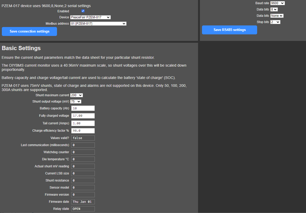
still waiting for 5 LM5009AMM to arrive (ordered in 21st Jan :frowning: ) in the meantime I ordered and today received a PZEM-017 shunt (200A).
Tried to connect it in either of my setups (one is 8S 304 EVE, the other is a test rig with 4S2P 18650) with no luck.
I think I got the settings right:

I also added a 110Ohm (cannot easily make 120 with the bits I have here guess it’s no big deal…) on the 50cm long bus cable from controller to shunt, wired the rest I believe right, but I get no values whatsoever as can be seen on the lower left of the pic above. Stuart’s video shows proper values there.
Now, one controller as a blob of solder on the JP4, the other hasn’t (the only think I’m not quite sure if I need it or not.
Running latest code (as in two weeks)
obvs missing something, anyone kind enough to point me to the right direction?

Mind, if I hit the save basic settings at the bottom, I get a refresh of the screen with all cells filled OK bar the 200A and the 75mV on the top of the section. Bat capacity, fully charged v, tail current, charge efficiency (I understand they don’t work with this shunt) values stay. The only two that mater just disappear.

cheers

V.

PS. I’ve not taken apart the shunt box to check for soldering failures, maybe I should!

I finally have assembled my test shunt.
But i am totally lost for the programming. i have a FTDI programmer laying around. Do i need something else?

Take a look at this video and see if it helps…

1 Like

Yes, you will need the blob of solder on JP4 - this simply adds the 120ohm resistor to the controller side of the connection.

Do you have the A/B connections around the correct way? Try reversing them on one side and see if that helps.

If this is the first time you have used the RS485 connection on the controller, it could be a bad solder joint around the SN65HVD75 chip.

thanks Stuart,

yes, got the blob, so that the 120Ohm is fine.
About to go to the local el.shop and get a few 120Ohm resistors for the box as multimeter currently shows 110Ohm (2X220Ohm I had around).
I find it hard to believe that two boards have both tiny leg chips (TCAs) working fine and the big bugger 8feet jobie failing… Unless it’s the wrong 485 chip!
maybe swapping A to B (I’ve followed your video so currently A goes to A and B to B)
will report back in an hour or so

V.

If you already have 110 ohm resistor, its probably okay - I also used an incorrect resistor value (115k) and it worked okay.

The next step is to connect the shunt to your PC using the supplied cable and see if that works - could be a faulty shunt?

A resistor and a handful of jumper wires: Current Monitor/Shunt - #67 by atanisoft

1 Like

thanks. just found a 4K7 laying around. but i dont get the software bit. did not found any kind of helpful manual

You can find pymcuprog via pymcuprog · PyPI. This will require using Python and PIP (package installer for python). There are other options available but this is what I use as other options did not work correctly under Linux or did not support updi over uart.

well i am looking for a windows 10 tool. i gues the pymcuprog will not be compatible.