It should work just fine. You can install Python from python.org (or windows installer as long as you get Python 3.8 or later).
well,
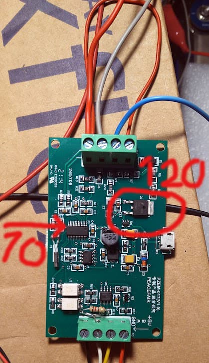
opened PZEM-017 up, B connection was slightly dodgy, resoldered and added a 120 Ohm resistor inside (there were pads ready for it)
nada, fwiw, the 485chip is nice and cool but the main logic/whatever chip is getting quite warm. Just found my IR thermometer, transistor is at 120C, the other chip at 70oddC. Unplugged it just in case…
wonder if I’ve wired the thing wrong.
rechecked and resoldered all legs of the controller RS485 chip. when running I get from the terminal:
_ __ _| o |_) |\/| (_(| | / |) | | __)
/
[I][main.cpp:3091] setup(): CONTROLLER - ver:LocalCompile compiled 2022-03-13T18:26:16.573Z
[I][main.cpp:3096] setup(): ESP32 Chip model = 1, Rev 1, Cores=2, Features=50
[I][HAL_ESP32.cpp:232] ConfigureI2C(): Configure I2C
[I][HAL_ESP32.cpp:291] ConfigureI2C(): Found TCA9534A
[I][HAL_ESP32.cpp:321] ConfigureI2C(): Found TCA6408
[D][HAL_ESP32.h:288] TouchScreenUpdate(): Touch = touch=0 pressure=0 x=0 y=0
[I][main.cpp:3118] setup(): TFT screen is NOT installed
[I][main.cpp:946] SetControllerState(): ** Controller changed state from Unknown to PowerUp **
[I][main.cpp:3133] setup(): LITTLEFS mounted, totalBytes=589824, usedBytes=98304
[I][main.cpp:254] mountSDCard(): Mounting SD card
[W][sd_diskio.cpp:181] sdCommand(): token error [0] 0x70
[W][sd_diskio.cpp:505] ff_sd_initialize(): GO_IDLE_STATE failed
[E][sd_diskio.cpp:775] sdcard_mount(): f_mount failed: (3) The physical drive cannot work
[W][sd_diskio.cpp:169] sdCommand(): no token received
[W][sd_diskio.cpp:169] sdCommand(): no token received
[W][sd_diskio.cpp:169] sdCommand(): no token received
[E][sd_diskio.cpp:194] sdCommand(): Card Failed! cmd: 0x00
[E][main.cpp:273] mountSDCard(): Card Mount Failed
[I][HAL_ESP32.cpp:140] ConfigureCAN(): CAN driver installed. Filter=1621098496 Mask=6291455
[I][HAL_ESP32.cpp:150] ConfigureCAN(): CAN driver started
[D][settings.cpp:20] ReadConfig(): ReadConfig diybms
[D][settings.cpp:42] ReadConfig(): checksum verified
[I][main.cpp:3157] setup():
[D][main.cpp:213] SetupRS485(): Setup RS485
[D][main.cpp:197] ConfigureRS485(): Configure RS485
[D][HAL_ESP32.cpp:86] Setasks(): Sleep
etOutputState 0=153
[I][main.cpp:.cpp:86] SetOutputState(): [D][HAL_ESP32.cpp:86] SetOutputState(): SetOutputState 1=153
[D][HAL_ESP32.cpp:86] SetOutputState(): SetOutputState 2=153
[D][HAL_ESP32.cpp:86] SetOutputState(): SetOutputState 3=153
Press SPACE BAR to enter terminal based configuration…skipped
[D][settings.cpp:20] ReadConfig(): ReadConfig diybmswifi
[D][settings.cpp:42] ReadConfig(): checksum verified
[I][main.cpp:946] SetControllerState(): ** Controller changed state from PowerUp to Stabilizing **
[D][main.cpp:770] tca6408_isr_task(): tca6408_isr
[D][WiFiGeneric.cpp:374] _eventCallback(): Event: 0 - WIFI_READY
[D][WiFiGeneric.cpp:374] _eventCallback(): Event: 2 - STA_START
[I][main.cpp:1444] connectToWifi(): Hostname: DIYBMS-00BADE2D, current state 255
[D][main.cpp:3362] loop(): total_free_byte=146976 total_allocated_byte=157112 largest_free_blk=113792 min_free_byte=146052 alloc_blk=285 free_blk=12 total_blk=297
[D][main.cpp:2442] rs485_tx(): PZEM_017 Read params
[D][main.cpp:2250] service_rs485_transmit_q(): Send addr=1, func=3, len=8
[D][WiFiGeneric.cpp:374] _eventCallback(): Event: 4 - STA_CONNECTED
[E][main.cpp:2398] rs485_rx(): Short packet 0 bytes
[D][WiFiGeneric.cpp:374] _eventCallback(): Event: 7 - STA_GOT_IP
[D][WiFiGeneric.cpp:419] _eventCallback(): STA IP: 192.168.178.132, MASK: 255.255.255.0, GW: 192.168.178.1
[I][main.cpp:1498] onWifiConnect(): Wi-Fi status=3
[I][main.cpp:1500] onWifiConnect(): Request NTP from time.google.com
[I][DIYBMSServer.cpp:2745] StartServer(): Start Web Server complete
[I][main.cpp:1532] onWifiConnect(): mDNS responder started
[I][main.cpp:1537] onWifiConnect(): You can access DIYBMS interface at http://DIYBMS-00BADE2D.local or http://192.168.178.132
[I][Rules.cpp:142] SetError(): Set error 4
[I][main.cpp:2718] lazy_tasks(): Task 1
[I][Rules.cpp:142] SetError(): Set error 4
[D][main.cpp:2442] rs485_tx(): PZEM_017 Read params
[D][main.cpp:2250] service_rs485_transmit_q(): Send addr=1, func=3, len=8
[E][main.cpp:2398] rs485_rx(): Short packet 0 bytes
[I][Rules.cpp:142] SetError(): Set error 4
[I][main.cpp:2729] lazy_tasks(): Task 2
[D][main.cpp:2442] rs485_tx(): PZEM_017 Read params
[D][main.cpp:2250] service_rs485_transmit_q(): Send addr=1, func=3, len=8
[I][Rules.cpp:142] SetError(): Set error 4
[E][main.cpp:2398] rs485_rx(): Short packet 0 bytes
[W][AsyncTCP.cpp:969] _poll(): rx timeout 4
[I][Rules.cpp:142] SetError(): Set error 4
[D][main.cpp:3362] loop(): total_free_byte=111360 total_allocated_byte=189092 largest_free_blk=79300 min_free_byte=102020 alloc_blk=506 free_blk=40 total_blk=546
so looks like rs485 on the controller sends packages, gets nothing back.
If I wire the RS485 signal to the USB cable, what would I use on my win10 pc to check that there are indeed data coming off the shunt and it’s not just dead?
cheers
V.
Did the shunt come with a USB cable? Mine did.
If you have a chip at 120C something is wrong - which one was this?
shunt on an 8S lifepo4 bank
yes, shunt came with a usb/485 whatever adapter.
Thing is I wire it, plug it on a USB port on my pc, then what?
use terminal or PUTTY to see if there’s something broadcasted, or any other win10 s/w I could use for debugging? I wonder if it’s broadcasting all the time, or only when queried.
Further, in theory this shunt takes VDC 5V from the controller board. which goes straight to the RS485 chip and runs it (I guess). In theory shouldn’t I have coms (even returning zero) with just the 4 cables (V+ A B GND) connected and no input from the shunt side? wondering how I could simplify debugging.
V.
Theres some crappy software you can download for Windows for it!
Heres a link - but no idea if its full of virus etc…
OK,
for anyone trying it, it does work. However, as usual instructions are bit strange…
So, unzip the file to a local folder,
fire up an ADMIN COMMAND PROMPT,
cd to that folder,
ran the run.bat which installs an ocx file
then run the PZEM003-Master.exe
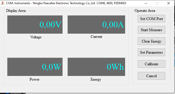
comes up with a window named:
COM. Instruments - Ningbo Peacefair Electronic Technology Co., Ltd
mine was on COM6 as found from Device Manager.
anyway to stop spamming the thread, no comms to the shunt, cannot set parameters, says Failed to read parameters!
so, my shunt is officially dead, will go through all the components with the soldering iron just in case…
V.
If you got it from AliExpress/Banggood etc. open a support ticket - they are usually quite good at giving your money back.
1 Like
nope, somehow i dont get it to work:
C:\Users\*****\AppData\Local\Programs\Python\Python310>pymcuprog ping -d attiny1614 -t uart -u com4
pymcuprog.serialupdi.link - WARNING - Check failed
have now ordered a NANO R3, let’s see.
Edit - formatted text. Moderator, BT
Can you add the verbose flag -v debug and see what it says?
yes:
C:\Users\******\AppData\Local\Programs\Python\Python310>pymcuprog ping -d attiny1614 -t uart -u com4 -v debug
pymcuprog.programmer - INFO - Setting up programming session for 'attiny1614'
pymcuprog.deviceinfo.deviceinfo - INFO - Looking for device attiny1614
pymcuprog.serialupdi.physical - INFO - Opening port 'com4' at '115200' baud
pymcuprog.serialupdi.physical - DEBUG - send : [0x0]
pymcuprog.serialupdi.link - DEBUG - STCS to 0x03
pymcuprog.serialupdi.physical - DEBUG - send : [0x55, 0xc3, 0x8]
pymcuprog.serialupdi.link - DEBUG - STCS to 0x02
pymcuprog.serialupdi.physical - DEBUG - send : [0x55, 0xc2, 0x80]
pymcuprog.serialupdi.link - DEBUG - LDCS from 0x00
pymcuprog.serialupdi.physical - DEBUG - send : [0x55, 0x80]
pymcuprog.serialupdi.physical - DEBUG - receive : []
pymcuprog.serialupdi.link - WARNING - Check failed
pymcuprog.serialupdi.physical - INFO - Sending double break
pymcuprog.serialupdi.physical - INFO - Opening port 'com4' at '115200' baud
pymcuprog.serialupdi.link - DEBUG - STCS to 0x03
pymcuprog.serialupdi.physical - DEBUG - send : [0x55, 0xc3, 0x8]
pymcuprog.serialupdi.link - DEBUG - STCS to 0x02
pymcuprog.serialupdi.physical - DEBUG - send : [0x55, 0xc2, 0x80]
pymcuprog.serialupdi.link - DEBUG - LDCS from 0x00
pymcuprog.serialupdi.physical - DEBUG - send : [0x55, 0x80]
pymcuprog.serialupdi.physical - DEBUG - receive : []
pymcuprog.serialupdi.link - WARNING - Check failed
Traceback (most recent call last):
  File "C:\Users\******\AppData\Local\Programs\Python\Python310\lib\runpy.py", line 196, in _run_module_as_main
    return _run_code(code, main_globals, None,
  File "C:\Users\******\AppData\Local\Programs\Python\Python310\lib\runpy.py", line 86, in _run_code
    exec(code, run_globals)
  File "C:\Users\******\AppData\Local\Programs\Python\Python310\Scripts\pymcuprog.exe\__main__.py", line 7, in <module>
  File "C:\Users\******\AppData\Local\Programs\Python\Python310\lib\site-packages\pymcuprog\pymcuprog.py", line 285, in main
    return pymcuprog_main.pymcuprog(arguments)
  File "C:\Users\******\AppData\Local\Programs\Python\Python310\lib\site-packages\pymcuprog\pymcuprog_main.py", line 80, in pymcuprog
    status = _start_session(backend, device_selected, args)
  File "C:\Users\******\AppData\Local\Programs\Python\Python310\lib\site-packages\pymcuprog\pymcuprog_main.py", line 549, in _start_session
    backend.start_session(sessionconfig)
  File "C:\Users\******\AppData\Local\Programs\Python\Python310\lib\site-packages\pymcuprog\backend.py", line 363, in start_session
    self.programmer.setup_device(
  File "C:\Users\******\AppData\Local\Programs\Python\Python310\lib\site-packages\pymcuprog\programmer.py", line 78, in setup_device
    self.device_model = get_nvm_access_provider(self.transport,
  File "C:\Users\******\AppData\Local\Programs\Python\Python310\lib\site-packages\pymcuprog\nvm.py", line 42, in get_nvm_access_provider
    accessprovider = NvmAccessProviderSerial(transport, device_info, baud=frequency, options=options)
  File "C:\Users\******\AppData\Local\Programs\Python\Python310\lib\site-packages\pymcuprog\nvmserialupdi.py", line 51, in __init__
    self.avr = UpdiApplication(port, baud, self.dut)
  File "C:\Users\******\AppData\Local\Programs\Python\Python310\lib\site-packages\pymcuprog\serialupdi\application.py", line 81, in __init__
    datalink.init_datalink()
  File "C:\Users\******\AppData\Local\Programs\Python\Python310\lib\site-packages\pymcuprog\serialupdi\link.py", line 45, in init_datalink
    raise PymcuprogError("UPDI initialisation failed")
pymcuprog.pymcuprog_errors.PymcuprogError: UPDI initialisation failed
pymcuprog.serialupdi.physical - INFO - Closing port 'com4'
Check your connections between the UART, resistor and UPDI connection on the shunt PCB. If all of that looks correct check the soldering on the ATTiny1614. pymcuprog is having an issue talking to the ATTiny1614 (no response).
1 Like
@stuart, Is there a way to test the shunt without the software? Just to ensure that the soldering has been done right?
Not really. You can do basic checks like ensuring there isn’t a short on the power input pins, but that’s about it.
1 Like
Hi, do you still have extra current shunt?
I’m down to one shunt PCB, there was one user who was interested and I sent a message to but I haven’t heard back or received funds for it yet. So if you are interested please send me a PM on here with your details and an email address to send a PayPal request to.
i really need your help. i do not understand the concept of getting the ATtiny programmed.
Meanwhile i got my breadboard, resistor (4K7), capacitor (10uF) and a ARDUINO NANO with a 328P chip.
I followed the youtube manual of proposed by @stuart. This seems to work.
whats next? Do i have to program the Arduino to pass on the .hex file? or do i past the code into the Arduino software to let the software compile and upload?
Tried it with this manual:
doubt that i have a fault on my board, as i soldered it with hot air and the solderjoints look good.
i have even changed the ATtiny1614 to make sure it is correct.
I have also measured the lines, Pin 1 - 5V, Pin 14 - GND and Pin 10 to Reset (470Ohm).
It worked finally! I did not upload the sketch correctly to the Arduino Nano!
See here, this helped me:

1 Like
For those who have the current shunt up and running, do you have any problems with the POWER reading on the web interface?
There is an open issue (link below) and I’m trying to find other users with the same problem.
hi,
got my first diybms shunt built finally after waiting for the LM chip for over two months!
well, did the initial powerup test, no sparks or smells, so looks fine.
Now for the programming, been through the thread a couple of times, have an uno and jumpers around, downloaded jtag2updi and using ArduinoIDE uploaded it to the UNO with no errors.
That’s on a win10 machine, now what?
I see that I have to use avrdude which I downloaded (from their site as a complied win exe) and fitted. but I’m struggling after that. i also see that I need to replace avrdude conf file with the one provided by jtag2updi, fine. The command line I see mentioned above by @shampeon :
./avrdude -v -C avrdude.conf -p attiny1614 -c usbtiny -U flash:w:diyBMSCurrentMonitor_ATtiny1614.hex:i
wont work as I don’t have a hex file anywhere 
Do I need to compile the code in PlatformIO and then upload using avrdude?
Basically, I don’t get the process at all!
I’m obvs missing something and the fact that I find PlatformIO an impossible tool to use doesn’t help (nor that I’m not a programmer…)
so any ideas how I progress from here would be welcomed!
OK, I’ll wire +5V/GND from the UNO to the +5V/GND of the shunt and D6 of the UNO to the Reset. Also I’ve disconnected the shunt from other powersupply.
And yes, I’ve downloaded and have on my PlatformIO dir the diyBMS-CurrentShunt-master and all it’s subfolders [which I don’t seem to be using for anything atm!].
cheers
V.
Hex file is downloadable from the releases in the repository.
I didn’t have much luck using avrdude, but was able to load the firmware using a USB serial connector and these instructions above.