Many thanks, yes it does seem to do about what its says on the tin. My 6kW is supposed to go down to 3kW, but I have never seen a level straight line anything like as low as that.
There is a Flow Temperure limit. Default min is 30C but this can go down to 20C.
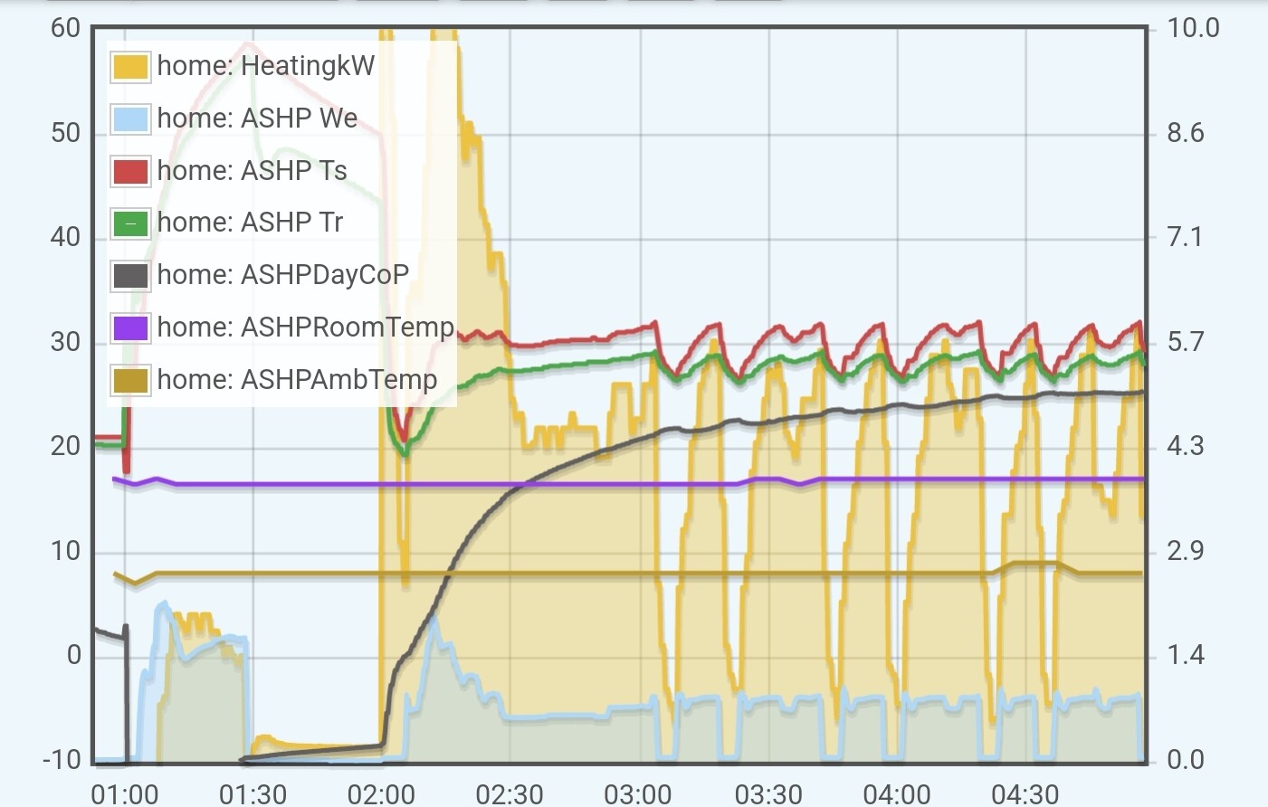
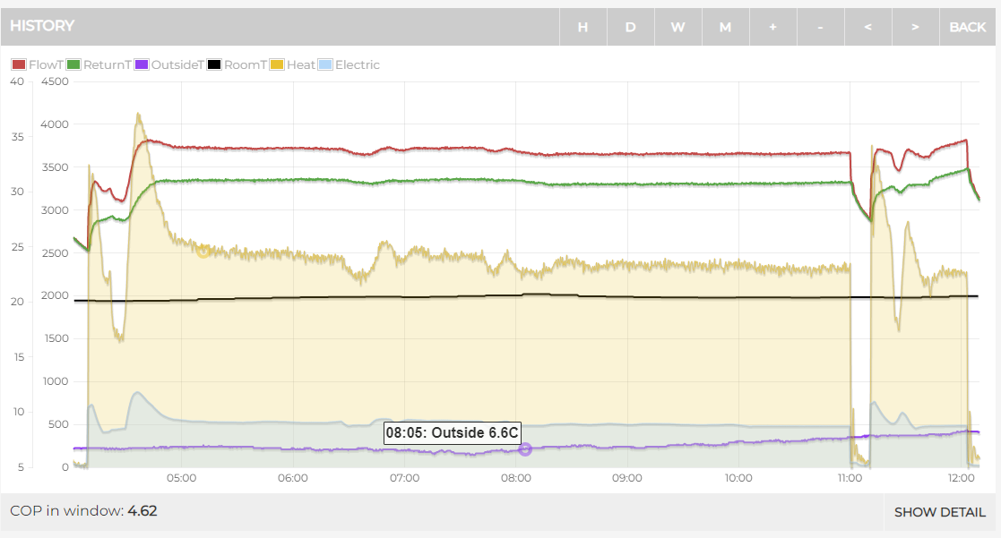
Gosh, the 6kW Vailant Arotherm Plus heat pump the heat geek folks are using seems to modulate down a very long way:
It appears to be consistently capable of running consuming just 440W and producing 2.3kW.
Although we can see it does have to turn off because even it can’t modulate down low enough to stay running all the time.
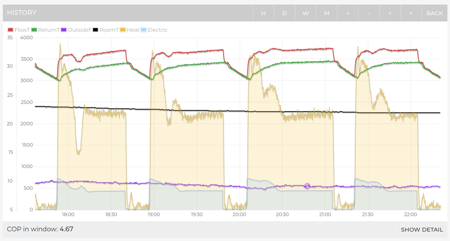
My Ecodan 8.5kW seems to have a minimum power input of about 650W - my elec measurement here includes 2 circulating pumps. But oddly it sometimes seems to prefer cycling at slightly higher power than running continuously at minimum. (Also, my CoP isn’t quite that good- i need to change my flow calc, but its in an Arduino and i havent got round to it yet!)
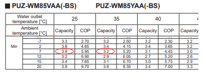
Interesting to see these graphs. According to the databook, the heat output should drop well below 4kW at your conditions. I have been emailing Mitsubishi since February, but not yet had an answer. My hunch is that whilst it seemed correct for the older R410a models, the newer models don’t drop to the minimum on the spec sheet.
Hi John
There is a databook for the R32 ecodan which presumably superceeds the older one - have you been using this?
I’m just about to post a python program that I have been working on which essentially incorporates and interpolates the data from the databook into a function that will return expected heat output for a given set of conditions - i.e input power , flow temp and ambient temp. I have managed to integrate it with my emonpi so I can show the result on the heatpump app and compare with the carnot value. Ive used the data for a 14kw unit but if you have the patience to type in the data for a smaller unit it should work the same.
It has certainly made the penny drop about the importance of reducing pumping power to the minimum - since intitially I forgot to account for this and was getting very high cops - I assume the data book is just for the bare outdoor unit and has no allowance for circulators etc.
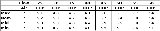
I thought that too, but looking at the performance chart for my model (PUZ-WM112VAA) for a given ambient temperature, the COP is actually higher at a medium power than at minimum. It looks to be the same for the 14 kW model too, yet small models see higher COPs at the minimum power.
I’m also not getting anywhere near these numbers with the system overall, including power to the pumps and losses along the pipes. I’m seeing COP about 0.5 below what’s shown in the databook.
It’s a 5kW unit, same as mine.
Yeah, mine regularly runs at 500W for 2.4kW / 2.5kW output
https://emoncms.org/energystatsuk
My installation needs it to drop to 7C or below for it to start to run long.
There’s a 7kW Arotherm Plus on the monitoring list that can do 600W low for 3kW too
https://emoncms.org/app/view?name=My+Heatpump&readkey=8e2d4547934319f9151a4730fb3e9f21
Although if you want LOW, Glyns 5kW Samsung can do 400W for 2kW
https://emoncms.org/samsung5kw
I’ve fixed my flow meter error today and added my heat pump to the monitoring website.
It’s available here: Emoncms - app view
I’ve also hooked up a Shelly IoT device to the ‘demand management’ contact; initially so that I can programme it in advance to switch off suring Octopus demand management periods, but maybe also to provide some better control in warmer temperatures - i.e. turning it off for while.
R
Hi Rachel - It would be great if you could share a bit more detail about how you connected your Sika flowmeter - I see it mentioned on several threads but no exact circuit diagram or terminal details on the FTC controller as far as I can see. I did investigate with a scope but managed to put the scope earth on the +5v dc supply to the flow meter pulling it down I think which stopped the heat pump and nearly stopped my heart pump too - luckily both recovered OK - but now a bit nervous to poke about. I am currently calculating heat output based on delta T and an assumed flowrate based on the reading from the FTC controller , not sure how accurate this is though. Are you making any allowance for glycol in your calculations and temperature effect on viscosity etc?
I was pretty nervous too, it was necessary to poke about with a multimeter to figure out which was the signal/gnd etc on the cable! I’ll try to do a quick sketch at the weekend…
Hi, Here’s the hook-up arrangement. Use at your own risk obviously ![]()
SikaFlowMeterHookUp.pdf (207.9 KB)
FlowMeterSketch.txt (3.6 KB)
Hope you don’t blow anything up…
Rachel
Thanks Rachel
I will have a look when I’m feeling brave
Mark
Can you share how you have set up control of your Ecodan 8.5kW and any settings you have changed?
Looking at how it is behaving it is doing a good job of continuous heating at a low level so would be interested to compare why our work’s office unit (same model) isn’t doing this.
Thanks for this Rachel, its useful to have detailed descriptions as starting points for those of us who bring zero experience to the task of setting up monitoring electronics.
You went route 1 and physically intervened in the wiring system. A less drastic solution was hinted at in another thread and has been expanded on by @TrystanLea in the documentation here: EmonTx4 Heatpump Monitor — OpenEnergyMonitor 0.0.1 documentation. The photos in part 3 show wires, doubled-up for some reason, in the block below where the Sika flow meter is plugged into the board. This bit of the technical docs shows the layout of the blocks at the bottom of the board and the reference to the flow meter at both locations – apparently allowing the Sika connector signal to be read from the lower block (I’m guessing that if you fit heat meters to the pipework this is where the flow data cables are wired in?).
FTC6 board.pdf (642.3 KB)
So far I have only got monitoring on the CU end of things, giving me the power consumption of my 8.5kW unit (which unlike Rachel’s seems to have a minimum working draw of around 1kW resulting in a lot more cycling unless it is decidedly cool).
I have yet to install at the cylinder unit end as I am still working up to the confidence to commit to programming an arduino-based solution to cope with several analogue readings and driving some 5V grundfoss sensors on the solar thermal. But soon, soon, …
In case it’s of some help to anyone: I can confirm that part of the TBI.4 block at the bottom of the FTC6 panel is wired in parallel with the flow sensor’s connector. I have a setup similar to Rachel’s, but measuring the voltage of pin 3 on that block relative to ground (pin 2).
I should probably introduce myself! I have had the 11.2 kW packaged unit installed for a bit over a year. I’ve noticed similar cycling issues to those discussed further up the thread, and have been progressively adding more monitoring to try to understand why it does this, given that you can see that it’s capable of modulating down far enough to avoid it.
Quite often the system gets in a cycle of ramping up aggressively, overshooting its target flow temperature, then abruptly stopping (or dropping to minimum power), waiting for a few minutes, then starting again. To me it just seems like a software problem: the hardware clearly could run consistently at an appropriate intermediate compressor speed – it’s just that the control system fails to find this speed in many circumstances.
Yes, I’ve seen this too. My solution is to limit the target flow temp to the return temp + 5 degrees (or whatever the optimal dT is for your system). This allows the heat pump to raise the temperature slowly without overshooting, and (maybe) reaching a steady state.
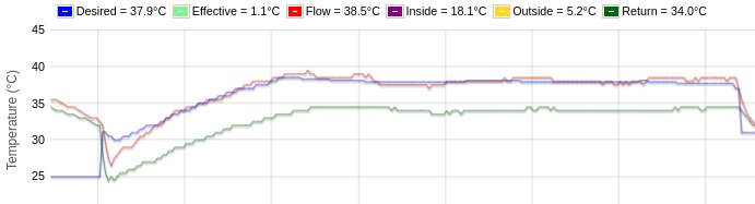
^ 6:30 until 10:30 am today. Compressor power was between 26% and 38% for this cycle, which is about as low as this unit* can go. [*EcoDan 11.2 kW]
This does require monitoring the heat pump very closely, and adjusting the flow temp every other minute. Here are some related threads that might provide interesting background:
That looks encouragingly stable! I’ll have a go at implementing something similar.
I suspect the issue is just the PID (proportional,Integral,Differential) parameters used by Mitsubishi in the flow temp control loop - set a bit too agressively leading to overshoot - I have seen the same on my 14 kw unit. Ramping up the setpoint is a good fix in the absence of being able to change the parameters of the control loop.
It continues to astounds me, that these very expensive systems appear to have such rudimentary control. Because 90% of the users never look at it, they get away with it! It really is scandalous.
It is almost as if they deliberately make it difficult to get the data out in case someone actually notices how rubbish they are!