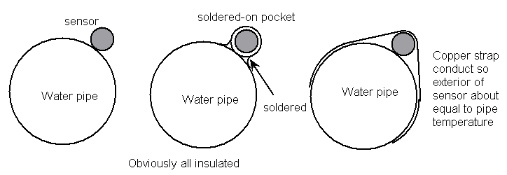
Its interesting that some sensors go into external pockets. These are a little pipe soldered to the pipe you are sensing. the temperature conducts around the pocket pipe, and it seems to work well. I have sometimes wrap a bit of copper around the sensor. It helps, but not done a lot of comparitive tests. Speed response will be better too.
With respect to calibration. You could put the sensors together for testing and add a callibration shift. I have done this several times. e.g. +0.25 or whatever it needs. You could also run the pump (easy on an Ecodan) and see if the sensors come together with zero dt. be mindful of water temp… i.e. it might be different at different water temperatures. The other point… I always remove the heat-shrink on the sensor if going direct to a pipe… conductive paste also helps…
If I had my time again, I’d fit sensor pockets into the pipework as it was being installed. (JTM Pipeline Brass Sensor Pockets | Plumbing Superstore®)
I have a number of sensors taped to pipes with Aluminium foil, under a thick layer of EPDM insulation and I’m sure the reading is lower than if they were in proper pockets.
Calibration is one of my moans - what can you use as your calibrated sensor? I have numerous types of sensors around and they all read a different temperature (when in the same location ![]() ). Even the rates of change and response curves are different!
). Even the rates of change and response curves are different!
Calibration here isnt quite so critical as other applications as we’re only looking at a differential - as long as they’re both consistently in error to the same extent. The DT will still be Ok.
I’ve used pipe earthing tags to fix my sensors to the pipe.
Rachel
Pipe earth tags sound great…
I dont callibrate as such, but sometime elastic-band a few sensors together and put them in a thermos flask. They are usually no more that 0.3deg highest to lowest. I simply add/subtract a bit of correction to some to bring them closer. I suppose melting ice and boiling might be a good-enough way of doing a slightly better job.
I think the response time is to do with how much air is in with the epoxy in the pocket… it could vary in a similar batch of sensors.
My beef is with different types of sensors; they all behave differently and it is impossible to know which one to believe!
I take your point. I tend to trust that PT1000 and DS18b20 are good enough. I try to ‘match’ calibrate around the range of use.
Hi all
I’m still mulling over which ASHP to get for my location and still have the 6kW R32 on my potential list. Although @johncantor struggles continue to give me worries, especially with his observations that the 6kW unit is just the 8.5kW in the same box, so it can’t run really low.
Note: my heat calcs come out at 5.3.kW at -3 with a flow of 42C.
So at 8C i’d probably only need 32C flow (approx 700W in / 2.8kW out)
Will it do that low? And go lower for 10-14C range?
But saying that all of this, any COP of 2+ is way better than the 0.85 i’m getting from my Gas Combi right now. ![]()
How are you driving your unit?
My preferred method would be weather comp from the unit temp sensor and then use an overnight setback of 18.5C or something like that.
Does anyone use an internal room sensor to help influence the curve? Apologies if that doesn’t make sense, but I’m not sure that is even a thing. I’m still trying to work out the control mechanisms available for each model. Is there even a room sensor for the Mitsubishi?
How close are folks getting to the interpolated efficiency charts that @MyForest created?
COP charts on a spec sheet are one thing, but real world data is far better indicator of performance.
Cheers, Mick
Here is a ‘snip’ of my 6kW unit, operating with around +10 to+7 outside air. I actually took it out of my place and fitted it on a friend’s good underfloor heating (50mm spacing!) to see how it performed.
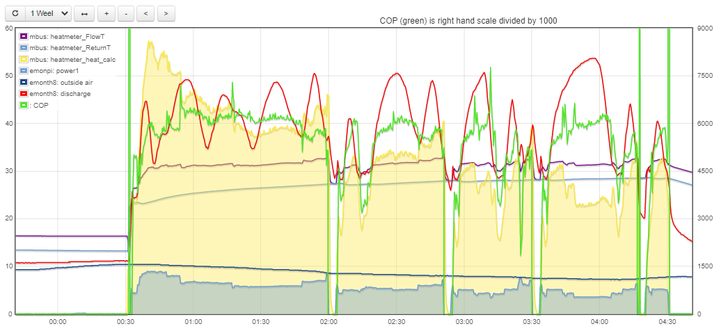
Anyhow, as you can see, it exceeds the 6kW, but that might be expected at such low flow/return temperatures. At just before 02:00 it ‘revs up’ where I would expect it to slow down, then it stops, then restarts only 4 mins later… annoying. The COP for first section is great, but at the end of the graph it cycles and the COP is considerably less. I have never seen it anything like the minimum output promised on datasheet. There is one reasonable section around 4am, but it doesn’t last long. Again, another unwanted ‘rev up’ followed by some messy operation. It is plausible that ‘rev ups’ are all to do with compressor lubrication, but they don’t seem to have done this control well. My 10-year-old unit does none of this.
Have you considered a 5kW unit?
What I don’t know is how well (or otherwise) Samsungs and Panasonics work. Not had the opportunity to properly monitor one yet.
My feeling is that few people are getting full potential… Maybe that is acceptable?? seems wrong to me.
@johncantor I’m beginning to get somewhere. I ‘calibrated’ my temperature sensors (one was about 0.2C different), and have now switched the pump onto a lower curve. The installer had left it on the maximum constant curve setting. I can now get the flow down to 12lpm and at the moment, with 6.5C ambient and a flow temp of 33C & DT of 4-5C I’m getting a CoP around 4.2. It was only doing about 2.0 with the pump at high speed.
However, in heating mode, there is very little head loss on the system (about 1-1.5m) because I have a low loss header, but with the DHW on (tank in the loft), on the current pump setting the flow drops to 6.5lpm.
The pumps are Grundfos UPS3, so I’m thinking I could use the FTC6 controller to set the pump speed using PWM as there seems to be an option for a different setting on DHW. I just wondered if you know whether the PWM signal is an industry standard? Will the Mitsubishi controller set the Danfos pump speed correctly?
Rachel
Well done… sounds good. The different resistance for DHW can be an issue. Mine is the other way around, and I put a gate valve to restrict it on DHW.
I don’t know enough about the Mitsubishi pump speed control. I thought it was simply fixed in the settings. Didnt know you could elect different speed for DHW. I assumed the speed control was not simply a switch-mode PWM. I would expect the ‘A’ rated motor to have a 0-10v or 4-20mA or similar control. I would like to know more about it.
I think this will come back to bite. Too many installers I think, just throw it in and walk away. They are not interested in investing the time and effort so the customer gets the maximum benefit. Jut not profitable.
There’s a terminal block labelled ‘PWM’ for the pump and it’s referenced in the installation manual, so it definitely has it. And my Grundfos pump definitely has PWM control option, the question is whether or not they are compatible! This article: PWM - Remote Control On Circulator Pumps - Plastmax describes how it works (and is the same as the Grundfos literature), so it seems likley there is an industry standard. I’ll do some more investigating, but plan to give it a go if it looks compatible.
If the FTC6 isn’t compatible, I might be able to programme the ESP8266 to do it - but that getting to the edge of my capability!
Email the manufacturer’s tech support. I have found them quite helpful usually.
Well done for digging into this. That looks like the pump speed has feed-back loop…good, I didnt realise it did that. I had thought (maybe wrongly) that the actual energy if these PWM pumps are less energy-efficient than best std ‘A’ rated pumps.
I have been using Wilo Pico. Sadly they are only manually speed-controllable, however, they do display (estimate) 3 things - input power, pressure and flow-rate. That is mighty useful.
Anyhow, ALL pumps should allow some sort of external controllability.
Which manufacturer? Mitsubishi always ignore me so far.
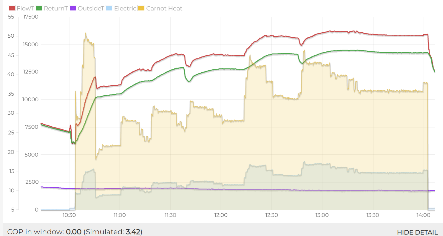
Hi , I have been monitoring out new Ecodan 14kw R32 unit - today I did an experiment in continuous running - I cranked the room stat (Nest) right up so I could be sure it would not try to stop the heatpump. In all it behaves pretty much as I would expect - there is a bit of overshoot on startup - on this occasion it ran through it but on other times it has caused it to stop - once it gets past this it seems pretty steady away - I stepped up the flow temp setpoint from 40 - 45 - 50 as well as twiddling a bit with one or two radiators and it all behaves itself I think.
Im a process/automation engineer by trade and have spent more than a few hours staring at trends of various processes and tuning PID control loops etc - I don’t know if the mitsubishi allows you to adjust any of the PID parameters (assuming they use PID control) or maybe they have some auto tuning thing going on - if not then I guess they will have set it up for an average situation - the main things that will affect how it reacts will be process deadtime and the time constant - i.e how long does it take from making a change before the controller sees the temp start to change and how fast does it change once it has started to move - both of these will be installation dependant - so I guess some will be better than others.
I would add that long deadtimes tend to make the process harder to control - imagine trying to drive a car with seconds of turbo lag. So presumably heatpumps miles down the garden with the temp sensors mounted in the house will struggle to settle more - having said that ours is about 10M away from the house and seems to be OK.
Always interesting to see graphs… I would like to see how it settles at the minimum end before it decides to stop. looks like it was a bit under 6kw at the start.
I know nothing about the control but someone told me that Mitsubishi Mr Slim Air Con protocol was freely available… No idea if that could relate to Ecodan, but he thought it did.
Hello John
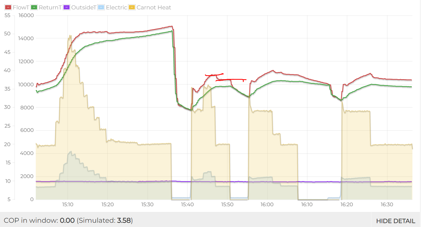
So I reduce the flow temp down to 35 Deg to see how low it will run. The first half of the trend below is doing a hot water cycle - after that it goes back to 40 Deg Flow and shortly after that I drop it to 35 Deg C - you can see it starts to cycle . To be fair the heat pump data plate indicates an output range of 4.5 - 14kw - and at the end of the trend the simulated heat output is 4.8 Kw - so give or take some errors it seems about right. One of the off periods the circulation pumps stopped - so I think there is a lower flow temp limit set by the installer - when I increased the setpoint to 36 it kicked off again.