It would be beneficial if you were pumping slightly more on the circuit side or at least matching your input from the heat pump. At the moment your heatpump is producing more heat into the buffer than is being delivered to your heating which will make your heatpump cycle more. So you are after trying to get your dT the same over the whole installation, if you have 40 degrees in at the buffer you want 40 out, 35 degrees back into the buffer and 35 out of the buffer back to your heat pump. That’s the ideal scenario.
At this point, both would be helpful to know.
Another interesting point to add is to see what pumps are fitted because most pumps now on the primary side are 7mtr as opposed to 5mtr normal circulating pump that installers fit on the circuit side.
For the purpose of this thread, I’d suggest downloading the minute-by-minute history from Melcloud since installation date for the past year, then uploading that to an Emoncms account. I’d be happy to help with that.
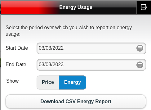
The CSV energy report contains raw minute-by-minute data for selected parameters for your device in comma separated variable format. This file will be 30-40Mb in size, and may take several minutes to generate and download. It is intended to be imported into a spreadsheet for further processing rather than read directly as a report.
Fields returned: TimeStamp, RoomTemperatureZone1, RoomTemperatureZone2, OutsideTemperature, FlowTemperature, EnergyConsumed, EnergyProduced, OperatingMode
These would be enough for My Heatpump app. Energy is in Wh, multiply by 60 to get power (W).
Expect to be processing around 525,600 rows.
What is main run from buffer/LLH? surely not 22mm plastic!!? Surprised flow is as high as 1100. You can experiment here with plastic & copper of different sizes https://heatpumps.co.uk/technical/flow-rate-and-pressure-drop-simulator/
Thanks all for the comments so far. I’m going to create a diagram of the system as installed and details of the equipment etc.
I’ll include as much detail as possible including length of pipe runs and diameter / material. I think this is probably the most helpful to support the discussion and I don’t want to waste anyone’s time by being unclear.
I’ll also summarise all the questions asked and respond / provide the data from MEL cloud etc as suggested. I’ll get to it as soon as I can!
In the meantime - feel free to keep asking questions! And thanks for the support already.
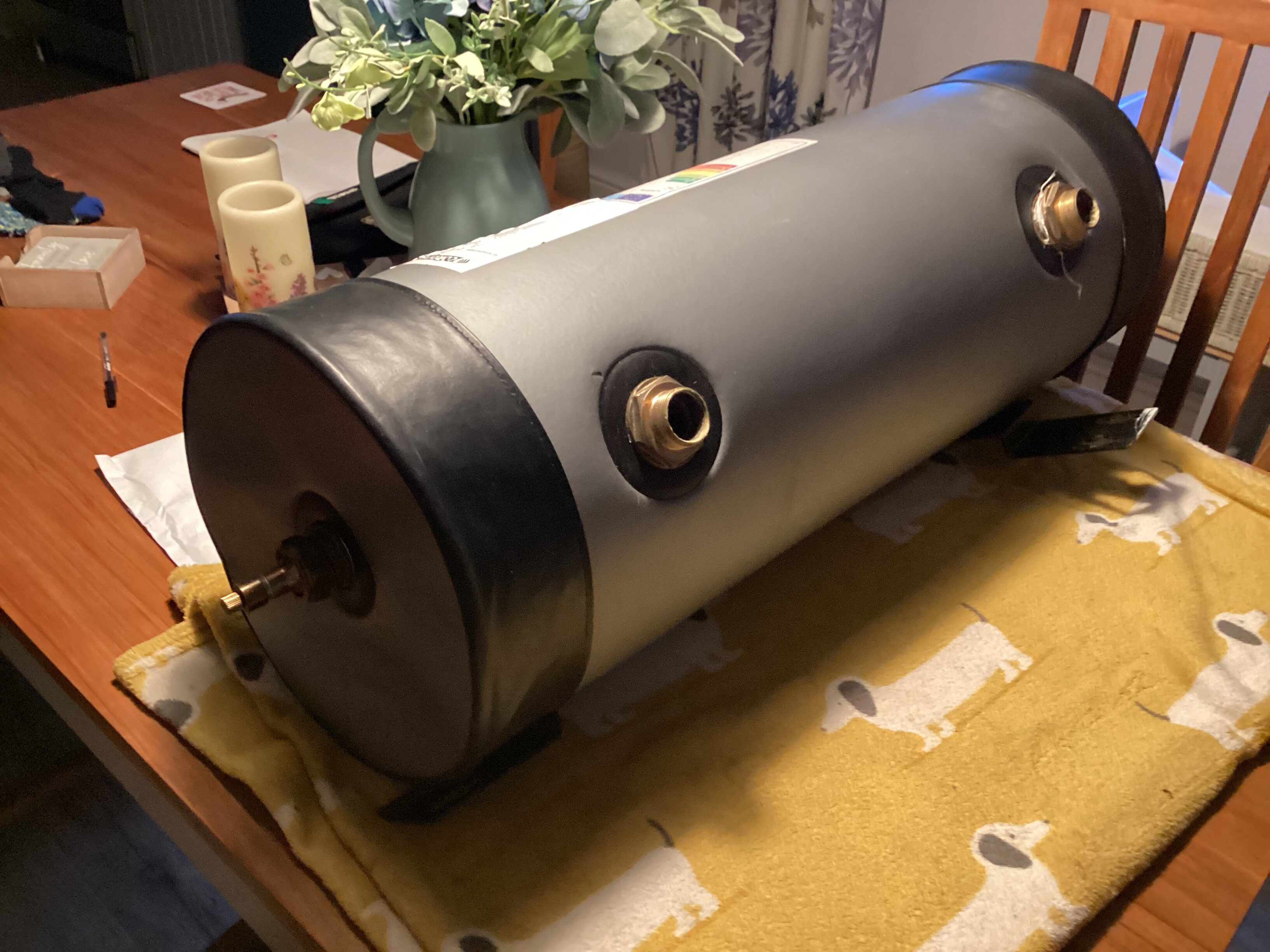
This is the buffer.
Central Heating Layout - Draft-3.pdf (244.6 KB)
As promised - here is a diagram of the layout of the system from the heat pump to the DHW tank and as far as I’ve got before the rads. I’ve included some notes on the second page with the current settings, and the heat loss calculations. I’ve done my best to include pipe size / material and included some details on the pumps.
Some additional information:
-
The cylinder and other pumping equipment are in an unheated cellar
-
The unit has been serviced regularly and filters cleaned
-
There is glycol in the system
-
The FTC/5 reports a flow rate of 19 via the service menu
-
The weather compensation curve is set to 50 deg at -3 and 30 deg c at 20 deg c
-
In terms of the monitoring equipment - the temperature sensors are (at the moment) only cable tied to the pipes in the locations on the diagrams.
Please let me know if this is helpful, I’ll get a diagram of the rest of the system tomorrow - including rads and as much as I know about the pipe runs.
To answer some of the questions to date:
@Satwelsh - sensors are attached to the pipework in the location shown on the diagram with 1 single cable tie - under foam insulation of varying quality.
@Timbones - the system was refitted by a second installer after the first one went bust, NICEIC involved - around December 2021 - buffer tank installed and 22mm pipe run installed from ground to first floor. I think its 22mm plastic once the pipework leaves the cellar, and 22mm copper on the return from the first floor (used the old gas return on refit due to problems with access) but can’t see the pipes
In relation to your question about energy use in hot water - children taking more showers as get older would be the root cause of this!
@johncantor - heat sensors are not in pockets
Thanks, Kevin
I’m not sure the diagram for the Sontex heat meter is correct. I’d expect to see 3 fittings:
- flow meter
- temperature sensor on flow from heat pump
- temperature sensor on return back to heat pump
The heat is measured by combining the readings from those three sensors. While it’s possible for flow and temperature measured by one device, your diagram only has the devices on the return pipes. So either there’s a mistake in the diagram, or the heat meter has been fitted incorrectly. If the latter, then that could explain poor COP values despite it seeming to perform okay.
You can ask the FTC to tell you what it thinks the flow rate is by going to “System” → “Running Information” → enter in 540. See this video for a guide (skip over pump speed bit). Compare that to what the heat meter reports.
“So either there’s a mistake in the diagram, or the heat meter has been fitted incorrectly. If the latter, then that could explain poor COP values despite it seeming to perform okay.”
@Timbones - sorry it’s an error on the diagram! It should read “flow meter” -
*now edited and uploaded to earlier post
There should be a second heat sensor on the primary flow - can you see it?
Yes - its there, now marked on the diagram. It appeared to be loose - came off when I took the insulation off. Now cable tied with 2 cable ties - and secured back under the insulation.
Which sensor will the ecodan unit be using to calculate COP / and delivered energy?
BW
Ecodan will be recieving pulses for each Wh measured by the heat meter, computed from the three sensors connected to it.
Heat meters need to be calibrated for the type of fluid in the system - if glycol has been added since, then the measured heat output won’t be correct.
On the Ecodan, is pump speed fixed at the setting chosen in the 540 variable? 1,2,3,4,5 etc?

Or is there a PWM option? Ie, it auto adjusts?
Also, is there a pump inside the outdoor unit? Or does the Ecodan always have an external pump?
W
The system has always had glycol in it. Whether it was ever set up correctly is another question!
COP is already looking more reasonable. Is the other sensor also secure?
Two different things here: The pump speed is set to a fixed speed, 1-5.
540 variable on the Running Information screen tells you the flow rate in litres/minute.
The primary pump is usually inside the building, next to the controller.
My understanding (so take with pinch of salt) is that you’d have Glycol in the heat pump side and then water in the radiator side.
Usually separated by a plate heat exchanger so you don’t mix the two fluids.
You don’t have a plate, so can the buffer provide that separation?
If not, has it just been filled with water now? Remember you’ve had numerous different engineers out?
So no PWM.
Okay, so thinking ahead, Kev needs to draw out the radiator runs (and the pipework diameter/lengths) so that we can work out the pressure drop/index circuit.
We can then use this to set the pumps on both sides close to that and to each other?
I’ll need to go round all sensors - others at first glance look secure but only one cable tie on each.