ZMPT101B, powerfactor and current shown

I will try to put some questions in one topic as the may influence each other.
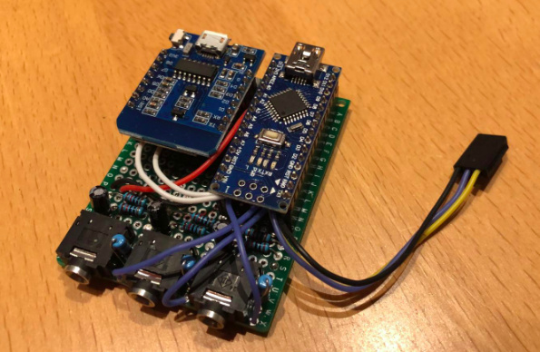
First of all I’m building this on an Arduino Pro Mini and a Wemos D1 for wifi and mqtt (but this is not of interest here).
I got everything up and running, reporting values to my mosquitto server, but was wondering why i got such high power readings.
So I went through the whole calibration test again. I got a good Fluke DMM and a high quality clamp amp meter for tests.
The setup includes 3x SCT-013-050 connected with 470k resistors and 10u cap and one ZMPT101B directly connected to the analogue pin of the arduino.
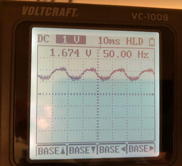
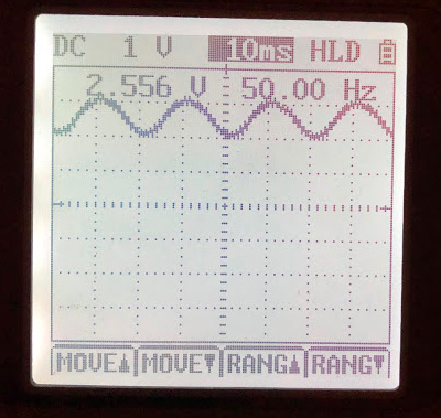
When I upload the voltage and current example I get theses reading (formated for better readability):

Voltage: 982.64 - Watt: 4234.60 - Amp1: 1.46 - Watt1: 1432.74 - realP: 738.88 - appP: 1432.74 - Factor: 0.52 - 
Voltage: 628.94 - Watt: 2598.75 - Amp1: 1.18 - Watt1: 743.91 - realP: 203.49 - appP: 743.91 - Factor: 0.27 - 
Voltage: 439.28 - Watt: 1873.78 - Amp1: 1.18 - Watt1: 518.27 - realP: 108.41 - appP: 518.27 - Factor: 0.21 - 
Voltage: 326.63 - Watt: 1350.76 - Amp1: 1.24 - Watt1: 405.66 - realP: 44.19 - appP: 405.66 - Factor: 0.11 - 
Voltage: 269.85 - Watt: 1066.26 - Amp1: 1.13 - Watt1: 303.77 - realP: 6.04 - appP: 303.77 - Factor: 0.02 - 
Voltage: 245.12 - Watt: 1022.71 - Amp1: 1.13 - Watt1: 277.30 - realP: -1.18 - appP: 277.30 - Factor: -0.00 - 
Voltage: 233.06 - Watt: 934.70 - Amp1: 1.16 - Watt1: 270.02 - realP: -10.81 - appP: 270.02 - Factor: -0.04 - 
Voltage: 228.72 - Watt: 879.71 - Amp1: 1.18 - Watt1: 269.41 - realP: 7.65 - appP: 269.41 - Factor: 0.03 - 
Voltage: 226.53 - Watt: 674.62 - Amp1: 1.09 - Watt1: 247.35 - realP: -3.38 - appP: 247.35 - Factor: -0.01 - 
Voltage: 220.91 - Watt: 1834.78 - Amp1: 6.43 - Watt1: 1419.74 - realP: 1254.13 - appP: 1419.74 - Factor: 0.88 - 
Voltage: 223.78 - Watt: 1851.07 - Amp1: 6.60 - Watt1: 1476.12 - realP: 1291.22 - appP: 1476.12 - Factor: 0.87 - 

As you can see voltage needs about 10 runs until it’s stabilised after resetting the Arduino. Is that ok? If not what would be causing that?

I then connected a simple heater (no motor, no capacitors etc involved) to calibrate the current (turned on for the last two reading above) and calibrate power factor. No matter what I enter in “emon1.voltage(voltagePin, VOLT_CAL, PHASE_SHIFT);” it will never go above 0.87, whereas it should be almost 1.00 for the heater alone. Correct?

Btw my VOLT_CAL is at 1.300(!!!) - never seen this in any other sketch?!
The CUR_CAL is at 105 for the 50A sensors. This gives reasonable values, the higher the current is, but it’s off by 1.5A where it should be zero.

Emon	Meter	Delta
1.56	0.05	1.51
1.70	1.02	0.68
2.24	1.54	0.70
2.90	2.52	0.38
4.10	3.77	0.33
4.95	4.48	0.47
8.16	7.75	0.41
10.67	10.17	0.50
14.08	13.42	0.66
17.27	16.70	0.57

Any help really appreciated. Thanks!!

image

BTW: I also read about buying assembled hardware, and I’d buy that, but am not really sure what to order to monitor 3 phases, and send the output to an mqtt server over wifi.
If someone is willing to help me on that, that may be the easier way??!!

What you’re reading there is the d.c. offset as everything stabilises and the high pass filter finds its working point. Are you using a recent emonLib? That has a slightly different filter arrangement and when correctly initialised, should offer a much improved start-up. It may well be that emonLib isn’t reading the correct value for the analogue resolution of your ADC, which is what it uses to initialise to.

That’s correct. PhaseCal is intended to correct for the combined effect of both the difference in phase error between voltage and current transformers and for the time difference between taking the voltage and current samples. Your problem, silly as it might sound, could be that the ZMPT101B has almost no phase error (20 minutes of arc). Without checking the sums, here’s something to try: edit your copy of emonLib so that the voltage and current readings are reversed, i.e. just swap the order of these two lines:

    sampleV = analogRead(inPinV);            //Read in raw voltage signal
    sampleI = analogRead(inPinI);            //Read in raw current signal

and try that.

Voltage and current calibration constants are the mains voltage and current that gives you 1 V at the ADC input.

For the ZMPT101B, that will obviously depend on the values of multiplier resistor ( R’ ) and burden resitor ( R ) that you have used. You need to tell me what those values are, or calculate the voltages yourself.

For the C.T, it should be 50 as the SCT-013-050 is a voltage-output device: 50 A : 1 V. So something is definitely wrong there - have you used a second, external, burden? (Because to get the voltage output, there is already a burden resistor inside the c.t. case :thinking: And if you have done that, that could be contributing to the false current readings you are seeing, because the output voltage will be about ⅓ of what it should be.)

What current does your Arduino give you when the c.t. output is short-circuited? Any reading there is noise picked up, either in your wiring or from the Arduino itself. Better filtering and good earthing on the power supply might help to reduce it.

If you want to abandon the Arduino, for best results you will need three emonTx’s with ESP8266 Wi-Fi adapters, each with one c.t., one a.c. adapter each measuring one phase, and a possibly one 5 V USB power pack each (unless all can share one USB power pack or a powered USB hub).
For slightly less good results, if you can accept the errors caused by using only one voltage measurement of one phase, you can use one emonTx with the 3-phase sketch to measure the three phase currents, again with the ESP8266 adapter to send via Wi-Fi.

Thanks Robert. Once again excellent write up and explanation. I will try and check what you proposed and report back.

You’re talking resistors of the current sensors, right? Which doesn’t make sense to me.
Silly me, I didn’t say that I use the “complete board” and not the transformer alone.

Do you want me to measure the resistors there?

I tried short circuiting the sensor’s input. This gives exactly the same reading as w/o current going through the line. Around 1.5A.

Swapping the reading of voltage and current didn’t change a thing. It’s exactly as before. With phase shift of 1.7 I get 0.82, no matter what.

That link tells me nothing useful, but worse, it is confusing me. This “Active Single Phase Voltage Transformer Module AC Output Voltage Sensor” seems to indicate that the output is a.c. (like a normal transformer) but this “Output signal: the output signal for the sine wave, the waveform of the median (DC component)” seems to say that the output is d.c. If it really is d.c, it cannot be used because the voltage input to emonLib is expected to be an exact sample of the mains a.c. wave. I need a circuit diagram to be able to know what the true action of the module is, and it would be far too difficult and time-consuming to derive it from the photos. It is certainly more complicated and has many more components than the circuit on the data sheet for the ZMPT101B.

If the output is d.c. but is not fully smooth, then your long settling time, your voltage calibration of 1300 and your inability to make the phase correction all start to make sense, because the filter is taking away the d.c., emonLib is measuring the ripple on the d.c. and that ripple is at 100 Hz and will be phase shifted relative to the mains wave.

That totally makes sense to me. I’m almost sure that this device outputs DC and not AC.
I just never thought about it, as I saw a lot of sketches that use that setup.

Just the first links on Google:

I will need to investigate more, and probable use the transformer alone, or rip off some parts of the PCB to make it output AC again.
You already helped me a lot! Much appreciated!

You sound more certain then me! If you look at Learn→Electricity Monitoring→Voltage Sensing→1. Measuring Voltage with an AC-ACPower Adapter→Measuring AC Voltage with an AC to AC power adapter, you can see what the emonTx/Arduino expects. In emonLib, to calculate real power, each pair of voltage and current samples are multiplied together to give the instantaneous power, and those instantaneous powers are averaged to give the average real power. At the same time voltage and current samples are each squared, those squared values are also averaged to give the rms voltage and current respectively.

If you rectify the voltage to give d.c. you can calculate the rms value because you know (or assume) the shape of the wave. But given the a.c. wave, emonLib calculates the true rms value whatever the shape.

My certainty is the main problem here :wink:. I guess to know everything just to find out that i know nothing. It’s for sure not the lack of reading as i have read all the links you gave.
I will start all over again and will surely solve it.

Try to check the circuit of your module against this diagram: problem with translate the values of voltage sensor ZMPT101B - Project Guidance - Arduino Forum
(from the bottom of problem with translate the values of voltage sensor ZMPT101B - Project Guidance - Arduino Forum)

All the resistors appear to have the same values as the photo. If it is the same, then the module DOES give an a.c. output exactly as you require (provided that the power supply is the same as the Arduino Mini - 3.3 V or 5 V), but you need to calibrate it as well as the sketch. You should have not more than 1.1 V rms out for a 3.3 V supply, or 1.6 V rms for a 5 V supply to your Arduino.

1 Like

Shame on me. First of all I ordered 100A type which don’t have the burden resistor inside. Then I switched to 50A types which have the resistor. Of course I didn’t change the PCB. So I can assume that CUR_CAL is 50 for that clamp meter. Correct?
Had a good read here as well: firmware for SCT-013-030 | Archived Forum

CUR_CAL is 50 for that current transformer with NO external burden resistor.

This is what by poor man’s shitty osci reads:

And the resitors do somehow resemble with the diagram you posted. Most of them are correct, but most of the 10k ones in the diagram are 5k ones on the PCB (well they are built in. Values (103) printed on them indicates they are 10k).

Both the Arduino and the ESP are powered by 5V from a AC/DC power supply connected to the same 220V AC as the voltage sensor. The 3.3V for the voltage sensor are taken from the Wemos D1 3.3V pin. All share common ground and VCC.

That does not sound right. The ZMPT101B module should give you a sine wave with an amplitude of 2.5 V centred on 2.5 V d.c. if your Arduino has a 5 V supply, so that you use the full range of the analogue input. But from what you write and that picture, you have the 3.3 V version of the ZMPT101B. The output of that can be no greater than 1.65 V amplitude centred on 1.65 V d.c., and you will only use ⅔ of the available range of the Arduino input. Though this is not ideal, it will work and the loss of precision will make little difference, but it does mean that emonLib will take a minute or two to settle.

And I do not like the high frequency superimposed on the wave. That should not be there.

I don’t think there is such a thing. Input is up to 30V if I can trust the description. But output will be altered by input I guess. So I will power it with 5V and see. The Arduino should be fine with 5V input anyhow.

You should power the ZMPT module from 5 V. When you do, it is likely that the high frequency instability will disappear.

That’s what I did. Much better result. And I now see the 2.5V. Also there is no “swing-in” anymore. I reboot the Arduino and it instantly shows the correct voltage.

If I set the PHASE SHIFT to -1.2 then I see a power factor of 1.00. With 1.7 it’s at 82%.

This is the oszi screen:

image

That is good.

Is that with voltage and current samples as originally written, or with the order reversed? Ideally, the number should be between 0 and 1, but -1.2 is OK (and yes, the default value is outside that range, but changing it would create a compatibility nightmare).

That is looking better. You might find that extra smoothing on the 5 V supply will reduce the high frequency ripples.

1 Like

The -1.2 is with sample order REVERSED. But i will try it the original way as well. You say, the ideal number is 0-1, but every sample I see uses 1.7. Why’s that? If “my” value is -1.2 is it ok to use it?

How would I smooth the 5V supply? I guess I should add caps to stabilize the voltage, right?

This still leaves one of the biggest problems open: Why is the current sensor showing (now with 82k resistors instead of the 10k ones) around 1A load, when it should show ZERO? The error gets less and less as current goes up, but especially at night when all three phases together should not exceed 300-500W, this can impose a HUGE error.