ZMPT101B, powerfactor and current shown

History.
If the order were to be reversed in emonLib, there would be less distortion and a much smaller change of amplitude of the voltage wave resulting from the phase shift algorithm.

Yes - it’s closer to the ‘ideal’ range then 1.7.

Yes, that would be my first move.

Which resistors do you mean?

As I wrote earlier, it is electrical noise that is finding its way into the ADC. Where it is coming from and how it is getting in is the real question. It could be on your mains supply and coming through the power supply to your Arduino, it could be generated inside the Arduino or from the Wemos and put onto the 5 V from there, and from the 5 V it could be getting in via the analog reference for the Arduino, or it could be coming through the ZMPT module. It might or might not be travelling on copper wires or p.c.b. tracks, it could also be inductively or capacitively coupled from one place to another close by.

Your oscilloscope pictures show a high frequency (approximately 1000 Hz) on the voltage wave. Where is that coming from? If it is also on the current wave, some if not all of it could be that.

1 Like

If I had a good way to read the 5V rail I’d do it. My oszi is not capable I guess.
I will try to rip everything apart, or build it new. Is it an issue if the arduino analog input wire to the sensor output is some cm long? Should it be shielded?
I also think that the resolution of the 50A sensor with (10bit?) resolution is around 28W @220V. So I can’t expect too much. Can I expect a ZERO reading at all?
The resistors I mentioned is the identical pair between GND / sensor / VCC. The ones that should be 10-470k.

With both the c.t. and the ZMPT module, the impedance of the circuit is so low that length - provided it is not really long, centimetres and not tens of centimetres, and screening should not matter.

Do you mean the current transformer? The value is not important when everything is mains-powered, and in many respect the lower the value, the better.

You don’t need those resistors for the ZMPT101B, because their function is performed by R4 & R7 on the module, which sets the quiescent output voltage to midway between GND & VCC.

You will probably never read a true zero, but you should get lower than 1 A. When you are calculating and reading real power, it will of course improve because you are not rectifying (in software), so the noise will tend to average towards zero. The effect of that is you have a low real power and a high apparent power, therefore a very low power factor.

1 Like

Thanks for making clear that the wires should not impose a problem.

I read that the higher the two resistors to the current transformer the better?! You say 10k is preferred, and NOT 470k? The whole thing is mains powered, yes. I was not talking about the ZMPT101B module (on the pcb) which, as you said, is directly connected to the Arduino.

When you say “something below one amp”, than this is what i have now, after added caps to the 5V rail. I get something between 0.4 and 0.8A. Which is ok’ish. I can add a formula to substract this from the real reading, as the error will be smaller and smaller the higher the amps are.

For mains power, yes, because the noise contribution is lower.
For battery power (as the emonTx was originally designed), those resistors are a permanent drain on the battery, so you need the highest practical value.

1 Like

Oh man. It seems you were soooo right. I now removed my $1 ac/dc power supply and fed the circuit with my (not super high quality, but still reasonable) bench power supply.
The result speaks for itself: Current reading at zero current goes down from 0.6A to 0.1A. That’s a value i can live with. There will never be a case that 20W+/- would matter.

But as soon as I connect the ZMTP cicuit (fed by the same 5V rail) it adds some noise to it as well, and current reading goes up to 0.4A.

What solution do you suggest to try. Any suggestion for caps (types & size) to remove the noise? And where to best place them? I know this goes way beyond the original emonlib question, but it may help others as well?!

Is the ZMPT module generating the noise on its output, or putting noise onto the 5 V rail, or both? Does your oscilloscope still show that 1 kHz ripple?

I would have expected C1 & C3 (on the circuit diagram of the module) to take care of any instability in the module itself. But it would be worth checking the module on its own when powered by your bench supply.

I haven’t analysed the signals. I just noticed that the current reading went up when I connected it.
Would you be so kind and tell me how you identified the 1kHz ripple? I just see a sine wave with little spikes, But I don’t see how you know that’s 1kHz.
In the meantime I’ll see if Google tells me something about “removing ripple” & “stabilising power supplys”. :slight_smile:

Looking at the waveform photo, it looked to me as if there were about 20 ripples per cycle of mains. That makes it 1 kHz. But if you expand the trace, you’ll obviously be able to count more accurately.

One thing is certain - it is not the clean 50 Hz wave that you should be seeing.

1 Like

After reading a lot if articles and watching YT videos i know that i know nothing. And measuring and removing ripple is above my level.
So i tried powering the arduino directly with USB and readings are quite ok. The fluctuate sometime between 0.15 and 0.70 A but are around 0.25 most of the time.

I compared to my owlmeter and it reads quite similar values.

What i still need to solve is the problem that mqtt server sometimes get 0W readings reported. No idea how that can happen. All 3 phases reading 0A for a fraction of a second.

Somebody else will need to help you with that - it’s something I know nothing about.

Did you manage to resolve your MQTT issues or open a new thread in another forum. I’m very interested in your project as it sounds very similar to mine. I’d be glad to help if possible.

My setup includes:

  • Arduino Uno - 2 SCT-013-000 clamps, AC transformer for CT1 and ZMPT101B for CT2
  • Serial Coms between devices
  • ESP32 - MQTT messages sent to server with Node-Red/InfluxDB/Grafana

Yes. This was solved more or less. I got some others issues now. I can post code here or somewhere else if you want and we can work together on it…

Just wanted to say thank you to iz3man for asking question pertaining to ZMPT101B PCB module, and a Huge Thank you to Robert.Wall for providing so much useful information!

I am using ZMPT101B PCB module in my project as well, and had many of the same questions :slight_smile:

I used 6.3V 10µF capacitor for my CT inputs, would this size capacitor be appropriate for smoothing the 3.3v input?(I am using arduino Due) or would a different size capacitor be better suited for smoothing?

You do mean the common 3.3 V power supply rail?

That’s probably on the low side of the sort of value I’d start with - the reactance is 160 Ω at 100 Hz, so it’s very likely you will need to use a higher capacitance than that. The upper limit would be set by the sort of power supply you are using. If it has what is known as “foldback current limit”, then too much capacitance will draw too much instantaneous current at switch-on and the power supply will promptly shut down. I’d probably start to wonder if I was doing the right thing if something like 470 µF didn’t show an improvement.

1 Like

The look at the module I had last month suggested to me the thing is very sensitive to environmental noise, due to the high number of turns in the transformer coils I think. I would expect there to always be noise present on the output of this.
I took the transformer off the module and rebuilt parts of the circuit. I was reading a signal at the secondary side plus burden with a lot of phase shift.
The module as a complete unit I think brings the phase back into line with the original signal (not perfect by a stretch) using capacitors and the op-amp. This has an important added effect of smoothing the waveform. Seems to me like any detail from the original waveform is lost.

As a complete module, I measured a phase shift of about 35deg.
. STM32/ZMPT101B report.pdf at master · danbates2/STM32 · GitHub

1 Like

each of my CT inputs has a 6.3V 10uf capacitor, The Arduino shield was based on: Home Energy Monitoring System

I need to check how much ripple is on mine with an oscilloscope, but I was referring to what you said here:

I am powering the Arduino Due with a 5v DC power supply: https://fccid.io/png.php?id=3234170&page=21

but all the CTs(the relevant part of the circuit), the ZMPT101B module and the w5500 ethernet module are all powered by the 3.3v rail on the Arduino Due.

You are talking about the capacitor that decouples the centre rail. I am talking about the 3.3 V and the 5 V supply.

This is a big clue:

The Ethernet module is where I suspect the noise is coming from. I think the 3.3 V rail needs cleaning up.

I’ve just thrown the circuit diagram of the module (beware: there’s a mistake - the input isn’t biased properly) at LTSpice and that shows a 24° phase shift at 50 Hz.

Here is the (simulation’s) frequency and phase response:


[50 Hz is near the centre, the 3rd harmonic at 150 Hz is near the bottom of the ‘bell’.]

My conclusion: the ZMPT101B module is unusable for energy monitoring, because it is impossible to correct that phase error inside JeeLib with the usual sketch. (It would mean storing the voltage samples for at least 24° worth of time, which would seriously complicate the sketch. It’s do-able, it’s how the 3-phase sketch works.)

There should be no problem with using the ZMPT101B on its own - without the the op-amps.

1 Like

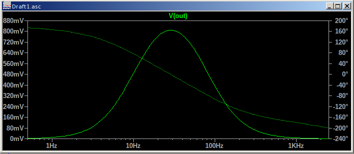
So removing or bypassing the op-amps would solve the issue of the 24 degree phase shift. I have to wonder what issue they were trying to solve by adding the op amp to begin with.

I am actually interested in trying to modify this ZMPT101B module so that the opamp is bypassed, I will have to see after comparing the schematic and the PCB if that is something i could accomplish, once I understand what it is that needs to be done to remove the opamp from the circuit. (I have a couple spares of this ZMPT101B module.)

Also I did find what you were talking about on the 3 phase sketch, phase 2 and phase 3 used the storedV variable array to offset the phase difference:

  if( PHASE == 2 ) {
    phaseShiftedV = storedV[(numberOfSamples-PHASE2-1)%PHASE3] 
                  + PHASECAL * (storedV[(numberOfSamples-PHASE2)%PHASE3] - storedV[(numberOfSamples-PHASE2-1)%PHASE3]);
  }
  else if( PHASE == 3) {
    phaseShiftedV = storedV[(numberOfSamples+1)%PHASE3] 
                  + PHASECAL * (storedV[(numberOfSamples+2)%PHASE3] - storedV[(numberOfSamples+1)%PHASE3]);
  }
  else {  // PHASE==1
    phaseShiftedV = lastFilteredV 
                  + PHASECAL * (filteredV - lastFilteredV); 
  }

I am in the US where we have split-phase there are 2 Legs of 120V each (60Hz), but It looks like I could adjust the logic in the 3phase sketch to correct for the 24 degree difference.(also because im on 60Hz and not 50Hz it would not be a difference of 24 degree correct?)

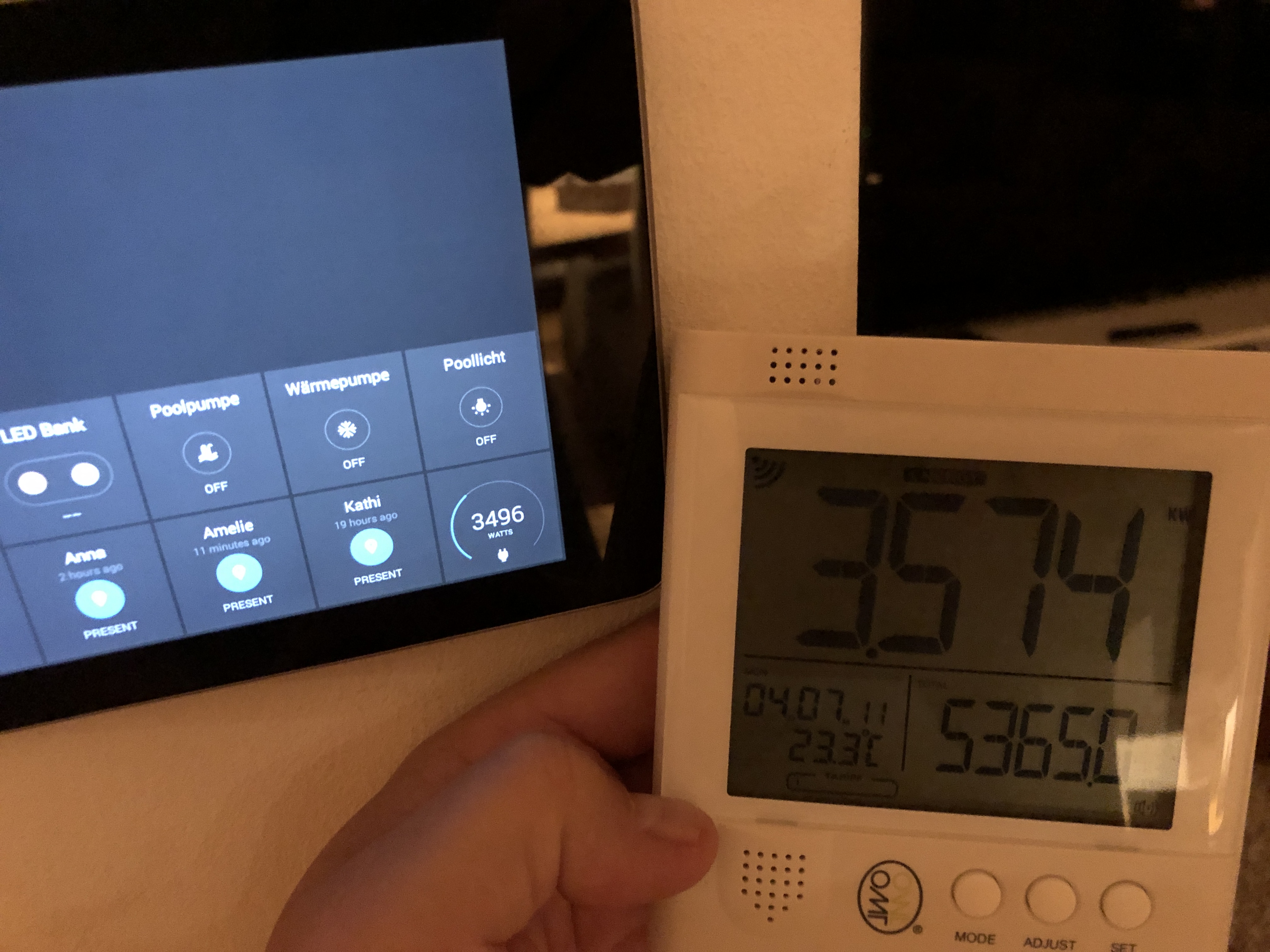
I originally used an AC-AC adapter but the voltage values returned by the “voltagage_and_current” script were not at all stable, it would on most loops return a value close to correct +/- 10volts but occasionally spit out a value like 400volts etc, which is so far off the mark its ridiculous. That is the reason that I got the ZMPT101B to begin with. I am wondering what the normal amount of voltage variance is when using a decent AC-AC adapter to sense the voltage, with the ZMPT101B its very stable, with a voltage of 120v expected, nearly all results return +/- only 1 volt so within 119-121 volt, or if my voltage from mains power is currently 117v then 116-118v, etc.

I am trying to use whatever solution or product will return the most accurate voltage reading.

When calibrating my Arduino, I am comparing to what my P3 kill a watt is reading, it has voltage, current, watts, va, and power factor that can all be displayed.

Not completely understanding the function of the opamp after reading wikipedia, I found this useful: https://www.youtube.com/watch?v=7FYHt5XviKc

Edit: so after watching the youtube video, and looking at the diagram, I see two Opamps, and both have the output going back to the inverting input, this suggests its for buffering based on what I saw in the video, Im assuming to get a more stable value? I do see that the output of the opamp does not go directly back to the inverting input, it has 2 paths, one has a resistor, the other path has a capacitor. After watching the video im guessing the capacitor in the opamp circuit is to help with the noise. All of this is new to me, I dont normally tinker with electronics, I am a software programmer, but I have installed all the wiring in buildings including the panels and/or sub-panels. I also see that the resistor path has both 100k then 10k to ground, so im guessing that means a gain of 10fold?