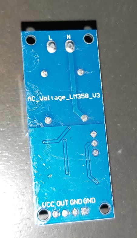
Yes! It appears I’m using a different module, and mine is marked “V3”, which is promising. The one posted in the previous thread has different markings on the bottom than mine does:
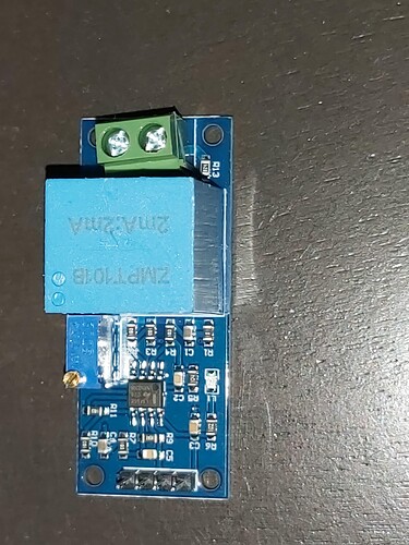
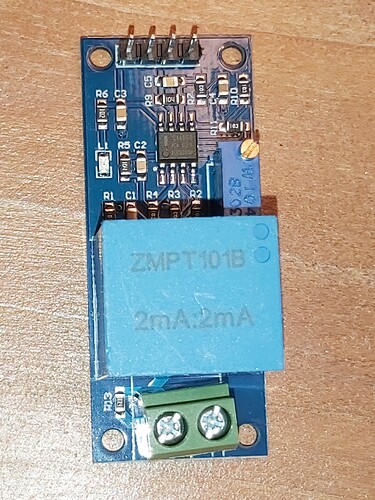
And unless I’m missing something obvious, my circuit has an R13, which your diagram does not, and the original poster’s linked module has called that resistor R12 in its place (next to the high voltage input terminals), so I’ve got an extra resistor somewhere.
Unfortunately the Amazon link I bought it from doesn’t have a schematic, and googling “AC_voltage_LM358_v3” doesn’t turn up anything at all. I can tell from the SMD markings that my resistors have different values than the ones marked on your schematic, but this board has traces on the top and bottom and possibly more layers in between, and tracing out a schematic for it is more work than I’m willing to commit. Here’s some links to hi-res photos of it from my cell phone if you’re interested:
I thought the issue was the op-amp itself introducing phase shift. And then the incorrect resistors on top of that. It sounds like if I wanted to use this board, I’d have to tap into a solder point before that op-amp and possibly modify some resistors. I’m more open to using it given that it’s already on a module board with nice convenient wire taps provided, if you think it’s that much better than the 24VAC adapter I have lying around. Especially if it has a known phase shift, since calibrating for phase-shift in the Arduino code sounds tricky.
Edit - attached pics to post. Moderator - BT


