You have a 3-phase supply in Denmark - is that 3-phase, 4-wire (L1 - brown, L2 - grey, L3 - black & Neutral - blue) 230 / 400 V, plus the safety earth? I shall assume it is.
[Your diagram is too small to read - can you post it here, please?]
If you want the best possible accuracy, then it would be one emonPi and two emonTx’s - one measuring each phase. If you are content with reduced accuracy, then you could have two emonTx’s each with the 3-phase sketch, one measuring the grid connection and the other measuring the PV infeed, plus an emonBase with emonCMS to collate, record and display the data.
For the emonPi option, you need 6 c.t’s, 3 a.c. adapters and a d.c. power pack & cable for the emonPi. For the emonBase option you need 6 c.t’s, 2 a.c. adapters and a d.c. power pack & cable for the emonBase.
(“Reduced accuracy” is because the emonTx has only one voltage input, so it must assume that the voltage of the other two phases is the same. How much error that will create will depend on how accurately the voltages are balanced, and you cannot control that.)
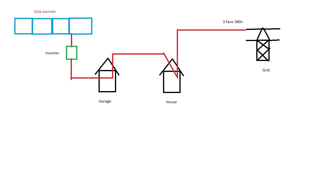
Can you access all 6 wires in one place in the house (3 phases from the PV and 3 from the grid)?
The way with the least work for you would be the emonPi + 2 × emonTx. You would use the standard default sketch in each emonTx, you will need to change the NodeID in one with a switch (but it is inside the case, so a Torx screwdriver is needed), and you will need to set up emonCMS (via a web browser) to record & show the information you desire.
It might still be a good idea to buy a programmer, even though you should not need it.
Your diagram showed the two coming together at the house - I had expected that would be at your distribution panel, where you would be able to access all the cables.
In this case, that first option is not available to you. You have little choice but to have one emonTx in the garage, and one emonTx in the house. Plus an emonBase - also in the house, I expect - to collect the data.
You will need a programmer, and you will need to download the 3-phase sketch, customise it according to your needs, and upload it into each emonTx.
And you need the emonBase. You will also need to set up the Arduino IDE on your computer to upload the sketch.
now i have setup all the gear. i ordered 2 emonTx one with id 7 and one with id 8 and a emonBase.
I have uploadet the 3 phase sketch to the 2 tx and in the sketch i have given them the id that there was writen on the outside of the tx box.
But i can only see the one with id 8 on the emonBase. how do i connect the 2’ one?
i also bought 2 temp sensors, and connectet them, but the temp shows up as 173 on the id 8 tx.
Both emonTx should have appeared. Can you confirm that in line 105 in the sketch, you have: int nodeID = 7;
for both units if you hare using DIP switch 1 to select the NodeID, or
int nodeID = 8; for the second unit if DIP switch 1 is OFF. (The switch when ‘ON’ adds 1 to the number set by nodeID, so I think you might have a wrong nodeID.)
Your emonBase should recognise the emonTx with NodeIDs of 7, 8, 11, 12, 13 & 14 (but not 9 & 10). So if you had NodeID=8 and the DIP switch ON, it won’t be recognised.
That is 17.3 °C. There is an error in the emonBase file “emonhub.conf” You can edit it via your web browser. The “scales=” factor for temperatures should be 0.01, not 0.1 The example configuration in comments at the top of the sketch is correct. You need to change this for both nodeIDs.
Every day a learning day. I wonder if the shop simply set the DIP switch therefore, so if @Bruno_Christensen did different sketches it would do as you said . Useful to understand, thanks. For my reference, where is this documented?
In general, or just for the 3-phase sketch?
In general - I wouldn’t know - you most probably need to read the sketch in question. The default sketch is nodeID=8, and subtracts one with the DIP switch. This probably goes part way to explaining why Nodes 7-10 are labelled emontx4 - emontx1 in reverse order. It would make a lot more sense for the default to be nodeID=7 and emontx1 and the switch to add 1.
For the 3-phase sketch, (a) in the documentation that’s part of the download, or (b) in the comments.
That’s exactly what I suspect has happened - they didn’t know the 3-phase sketch would be loaded and assumed it would be the default single-phase one.
Nodes 9 & 10 most likely won’t work for anyone, as emonhub expects a signed integer for the pulse count, whereas the sketch sends an unsigned long.
[I’ve flagged this to Gwil in PM - hopefully he’ll correct the faulty emonhub.conf]
You thought you had one Node 8 and the other was not working - you actually had both reporting as Node 8. You might have seen the values reported varying because it would show the value for one, then the other.
If you turn off the DIP switch for the one with int nodeID = 7, then that one will appear as Node 7. There is no need to edit and reload the sketch, but you must press the reset button after you have changed the switch, because it only looks at the switch as the sketch starts.
No, it is definitely not normal, unless you are using sensors that are not our standard ones.
The calibration of the 3-phase sketch as distributed is set for the emonTx V3.4 using the standard UK a.c. adapter and 100 A current transformer - as given in the documentation (“emonTx 3-phase PLL User Doc.pdf”) that was included in the zip file you downloaded.
Which a.c. adapter and which current transformer are you using?
6 ?
Do you not have only 2 emonTx’s?
You can expect the calibration for each main channel of the emonTx’s to be close, but I do not expect all to be exactly the same, because each current transformer (our standard) has a tolerance of ±3%, the a.c. adapter likewise. And then you must add the tolerance of the components inside each emonTx. But that does not account for an error of ½ ×.