Is there a similar Arduino sketch for the pulse counter instead of using CT’s?
Thanks
Simon
Is there a similar Arduino sketch for the pulse counter instead of using CT’s?
Thanks
Simon
@swynne. This is the only sketch I have but it could be modified. How do you mean “pulse counter”? Are you looking to track frequency?
I think Simon cross-posted. See ESP8266 Dev Kit - pulse counter
I’m assuming from the context that it’s pulses from an electricity kWh meter that he wants to count.
Got it. Looks like Simon is in good hands. @swynne-- Having used dozens of microcontrollers I would only add that the ESP is a nice little inexpensive option but it really excels at using its built-in WiFi stack. Other Arduino variants may be easier to use given the many display options.
Great to hear Dale.
Love the Pi etc but want a one board solution to enable inputs and send be data to the web etc for reporting and this seems to fit the bill. Need to get it working first though!
Simon
I agree that the ESP is a great choice for sending data to the cloud. I
see in the other thread that you got great suggestions as to using existing
sketches that do the pulse counting. I have not looked at the code but
unless the interrupt based code is already written for the ESP, you may
find the loop based pulse counter more straightforward to use.
may i ask a (stupid) question ? what’s a CT ? i currently have an adafruit esp8266 as well but the only thing i created with it was a temp monitor logger to mqtt, i tried a battery temp sensor using deep sleep, the deep sleep parts work but still drawing too much current and batteries died quickly but the deep sleep stuff was working.
Anway am i correct in the understanding that this circuit is used to monitor electricity (power) usuage in someway?
How exactly does that work if that’s the case and do you have to hook it up at the meter or can it be used as a general purpose meter in some way ?
My problem is that my meter is very old and not in my appartment, but in the basement in the same room as my 40 neighbours meters so there’s a lot of meters and it’s publically accesible. I’m also from belgium so 220V here and don’t know the meters how they work. the fuse box in my apt itself only has the fuses accessible and nothing else as far as i could see (that’s why i’m using wemo insight’s to monitor my appliances).
But if a circuit using esp8266 can be easily build to record power usuage from my meter in the basement someway i’m highly intrested the only problem is powering the esp8266 as there’s nowhere any electircal outlet plug in an adapter.
not sure if it is such a circuit (can’t tell by just readin the thread) .
A CT is a Current Transformer. It’s like a little donut that is placed around one line of the power (not both). It generates a voltage linear with the amount of current being drawn on the power leg. Some cts require a burden resistor to be used as well. So to do what you are suggesting you would need access to inside the panel that provides your power to place the CT. The ESP has a single analog input that can read the CT output. But you will need to power the device. There are some articles that talk about using batteries and deep sleep that work for up to a year. This assumes you only wake up once every few minutes to take a reading.
Thanks for the explenation, that’s all really intresting and might be something i’m willing to use / create but i’ll dig some furrther first on the information i can find
Sorry, but Dale has given you completely wrong information there.
A CT does not generate a voltage, it generates a current. The purpose of the burden resistor is to turn that current into a voltage. Some CTs have the burden resistor incorporated in the case that houses the CT. Most analogue to digital converters - the first stage that the signal hits - require a voltage, not a current.
The CT measures the current in the cable. Knowing the voltage, you can have an estimate of the power that you are using, and by measuring that at frequent and regular intervals you can get a value for the energy consumed, but for complicated reasons, that is unlikely to exactly match the readings of your electricity supplier’s meter.
Are you able to have access to the cables inside your apartment, or can you have a local electrician fit a CT for you? That would be a much better answer, if possible, because everything would be within your apartment.
Thanks robert. I don’t want to hijack this thread so i’ll keep it short. There is no way i can access cables inside my appartment unless i disassemble the fuse box housing and i don’t want to go that route. Since you mentioned the readings are not accurate (compared to the meter) i think i’ll stick with my smart enegery meter plugs (insight, maginon) approach as this also is not 100% correct, i get about 10-15 KWH monthly diffrence, but that’s because i’m not measuring the power used by my lights and washing machine i think. I’ll have a search for some fittings to add to my lights that can read the power if that exists and buy one more wemo insight for my washing machine. I’m already more than happy with the readings i can do now with the smart energy plugs
Your alternative might be an emonTx / emonPi pair. The point about the emonTx is the RFM radio module uses quite a bit less energy than WiFi, so you should get a reasonable battery life. You put the emonTx by your meter. Then you site the emonPi in your apartment. If you have a socket near the meter, you could use that to measure the voltage and have a measure of real power (and you wouldn’t need batteries!), otherwise you would only have the voltage in your apartment, hence you could only calculate apparent power (Vrms × Irms), which would normally be somewhat larger than real power.
Hi @dvanaken and guys,
I came across this thread because I have a similar project - using only esp8266/nodemcu - but I measure voltage only.
I have an issue that the wifi of the NodeMcu always got disconnected - I am using emonlib - but I modified it slightly so it measure one analog input input (A0) only. The wifi works (ping-able) for couples of second, and then got disconnected. I notice that the wifi got disconnected the moment the sketch starts reading the analog input ( calcVI());.
After some investigation, I found that reading analog input very fast or too frequent (in a while loop for example) and relatively long duration will force the wifi to disconnect. Please see here and here.
Some says adding yield() or delay(0) in the void loop() section within the sketch or inside the while loop could help (to avoid the wifi disconnect issue), but I tried that and it does not work either.
I assume you use Arduino IDE, do you manage to make the wifi working with your sketch ()? If yes, do you mind to share your sketch (if it’s not a secret  ), or give me direction on how to workaround this issue?
Thanks in advance,
miq
Hi,
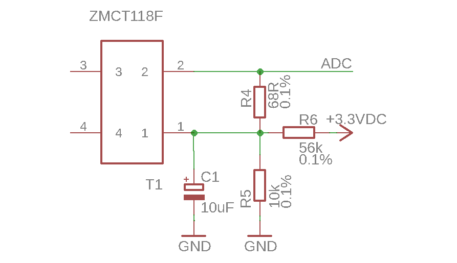
I want to use ZMCT118F current transformers with the ESP8266-12F ADC input.
What circuit would I need and what burden resistance values for a maximum of 5, 16 and 30 A?
Thanx for any hint! 
That c.t. is 30 A : 30 mA.
The ADC input on your ESP8266 is 0 - 1 V.
Therefore, you need a similar circuit arrangement to that in ‘Learn’ for the Arduino (Learn | OpenEnergyMonitor)
BUT you must calculate R1 & R2 to give you 0.5 V d.c at the “mid-point”.
The burden voltage wants to be about 5% below 1 V peak to peak, so the rms value will be not more than 0.335 V rms.
Therefore your burden values will be 67 Ω for 5 A, 20.9 Ω for 16 A & 11.16 Ω for 30 A. You must choose the next lower standard value so as not to overload the input (62, 20 or 18 & 11 or 10). If your midpoint is accurately at 0.5 V, you should be able to use a 68 Ω for the 5 A range and not clip the input - but it depends on all the resistors being close tolerance (1% or better), and the analogue reference being not less than 1.0 V.
Not so much to directly answer the question asked here, but for the benefit of anyone else who may want to use the ESP8266 ADC, and doesn’t have a particular CT in mind, one of the 0.333 Volt CTs so commonly available would also work, would it not?
Indeed it would - and of course since the output is a voltage (meaning that the burden is internal), no external burden is needed.
A peak inrush current of 7 A might just be OK, but you might like write into your software a check for the highest and lowest sample from the ADC, before you do any calculations on the sample values. If you get a value greater than 1018 or less than 5 (say, meaning that you are very close to clipping) then you should reduce the value of R4. If you don’t come close to clipping, then R4 is OK, and the other components look correct also.