Strange LTSpice Simulation result on emonTx v3 AC Voltage Sensor Circuitry

Hi,

I want to replace the controller board of an old 3000 watt dc-motor-controlled voltage stabilizer. I am planning to sense the voltage from the built-in secondary winding of the voltage stabilizer, and based on the sensed voltage, stabilize the voltage by controlling the motor using L289N motor controller. Also I am planning to use esp8266 as the micro-controller.

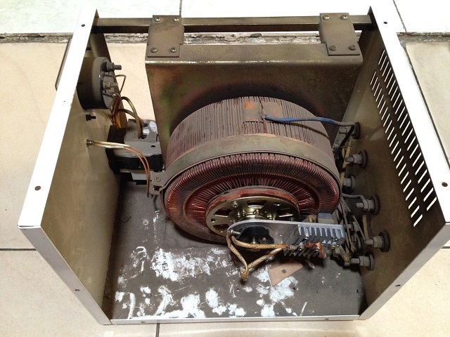
For anyone interested, here is the photo of the voltage stabilizer I was talking about:

It was suggested in several places in this forum that, to be able to power the microcontroller (esp8266 in my case) while simultaneously monitor the AC voltage using only one transformer is by using half-wave bridge rectifier - which is currently implemented on emon Tx v3.
I then study the emonTx v3.4.2 circuit - found on Github - particularly the AC Voltage sensor circuitry.
To get better understanding of how the circuit works, I then simulated the circuit on LTspice, before I put it on simulation board / breadboard.

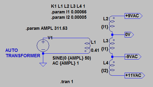
But the result I got was very strange, please refer to the circuit below:

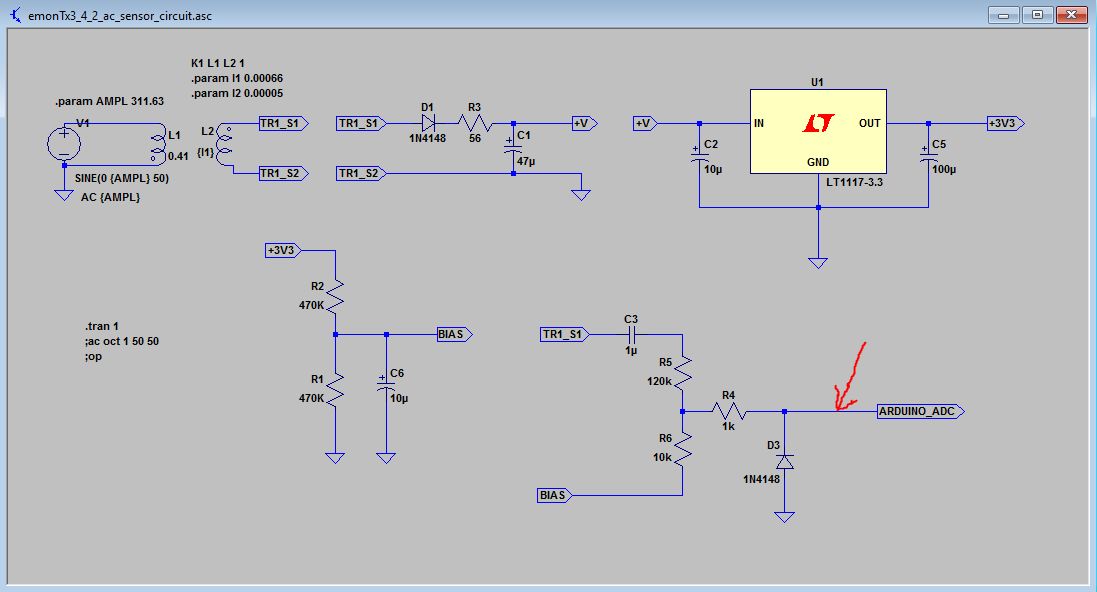
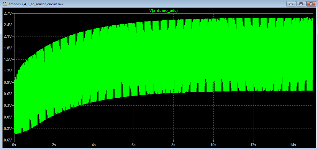
With 1 second simulation, this is what I got if I place the probe at ARDUINO_ADC net (indicated by red arrow in the picture above):

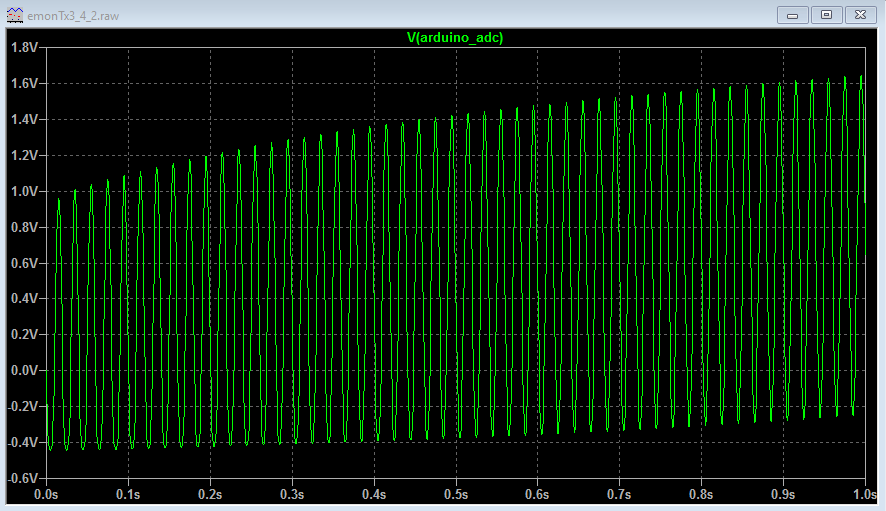
As shown in the screen shot above, negative voltage from 0 volt to -4 volt exist!
And also it seems the voltage is steadily increasing, but very slow.

Of course the circuit on Github is correct, so I must have doing something wrong in the LTspice simulation.

Can somebody please help me point out where or what I have done wrong…?

For anybody interested in testing the LTspice schematic I made, I have attached it here -
emonTx3_4_2_ac_sensor_circuit.zip (159.9 KB)

I admit I am very new to simulation software (LTspice etc.), but I’ve been learning it so hard for a few weeks now :grinning:
Also I don’t have good basics on electronics, but I have built several diy projects in the past (mostly diy guitar pedal fx projects and couple of arduino projects) with fair success.

Any help or advise are really appreciated.

Thanks!

It is very simple - you have not let the simulation run for long enough. What you are seeing is perfectly OK. The bias circuit has a fairly long time constant (as you’d expect from the component values) and you’ve only let it run for one second. If you think about the power-on test sequence of the emonTx, it takes a lot longer than that, so no values are calculated for something in excess of 10 s after power-on.

Thank you, thank you, you are absolutely right @Robert.Wall, thanks for pointing that out!
I did not know that the component values of the bias circuit also influence the time constant - I thought it’s job was only to divide the voltage.

I tried again with 15 seconds simulation time, and this is what I got:

As Robert has explained, the voltage start to stabilize at around 10s - cool, I learn something again!

Another question is about the negative voltage that exist between 0 - 2 seconds on the output of 120k/10k pair resistor. Based on the schematic, it is then fed directly to atmel / arduino ADC pin.

Is that okay for the ADC pin? Because as far as I know, ADC pin of a standard arduino cannot withstand negative voltage?

Thanks for the enlightenment in advance.

But that voltage needs to be stable, the capacitor is there to feed the current that’s needed to charge the sample-and-hold capacitor inside the ADC. The Atmel data sheets have all the details about the source impedance upper limit - it’s 10 kΩ from memory. The time constant is that charging through the divider chain.

The input pins cannot read a negative voltage, but the protection diodes can tolerate a small negative current. The reason for the series 1 kΩ resistor is to try to limit that current. While you’re in the data sheets, you can read about that too - or there’s quite a lot in the old forum.

Thanks for sharing Robert. I read your reply 3 times or more trying to understand it and still even more questions are arising in my head!
I’ll have a look at the Atmel datasheet first, and digging the old forum - well actually all the suggestions to use half-wave bridge rectifier I got after reading your comments in the old forum, and thanks for that!

I hope I will get better understanding to what you’ve explained in the reply above, after looking at the atmel datasheet.

One more questions Robert, it is explained that the circuit to power the emonTx v3 is limited to around 20mA only.
Do you mind point me out which component in the circuit that provide this limitation? Was that the 56 ohm resistor after the bridge rectifier diode?

From what I understand, the current is limited to maintain a nice AC sine wave form coming out from the transformer, hence maintain accurate voltage reading.

Since I need more power in my project - I estimate it is somewhere around 400 - 450mA maximum - because besides powering the micro-controller (esp8266), the same transformer will also be used to power the dc-motor and motor controller - so I can tolerate if the wave form is altered a bit more - as long as it can still sense the ac voltage variation quickly - so high accuracy voltage reading is not a priority, well… in certain degree :grinning:

Any suggestions are really appreciated.

The real limit to the current that you can draw is the effective impedance of the transformer, because it’s inside that component where the voltage wave gets distorted. What voltage are you trying to measure - is it the mains or is it the transformer output? If it’s the latter, then the transformer impedance doesn’t matter. If the former, then anything you do that means it’s not a faithful copy of the mains supply will give errors. If those errors are linear, calibration will solve that. Otherwise - and this is the original problem - it means that the shape of the wave is distorted and the you’re measuring the wrong thing.

What I think you need to do is include the transformer (the real one that you’re going to use, not an ideal one) in your simulation, add the loads that the ESP, motor and controller impose and see what you get for the shape of the wave that you’re measuring.

I am measuring the transformer output (secondary winding).

From what I understand, the primary winding in my voltage stabilizer is an auto-transformer, and then there’s a secondary winding built-in inside it, with 4 outputs. Based on my investigation, the configuration of the secondary winding is 9-0-9-11 volt. I am planning to use only the first half (the 9-0 output) of the secondary winding, and I will tap from those outputs - to measure the ac voltage.

Well I hope I am not complicating the situation by using only 2 outputs of the transformer.

That’s the harder part :grinning:
Ehmm, I don’t think there is a component provided in LTspice library for a real transformer. I will google it now, hope I can find one and then do your suggestion - put all the load in the simulation.

EDIT:
The wiring of the transformer in discussion is something like this - based on my best knowledge :neutral_face:

It is time to make your own (or modify one). That will not be easy. You need to look in an electrical engineering text book (or on-line, but choose a reputable source) for the equivalent circuit of a transformer, then measure the parameters of your transformer and adjust the values in the Spice model to give the same result as the real one does, under the same conditions.

I admit I didn’t develop the full model for the Ideal a.c. adapter, I simply added a series resistor in the output to represent the regulation.

Thanks Robert, I tried google and found a good LTspice wiki here.
I read it thoroughly and try ti understand it - but as you said - it is very technical - probably I only ever heard 10-15% from the technical terms they have used there, perhaps less than that :grimacing: :cold_sweat:

But the wiki also explained a good guidance, like placing series and parallel winding resistance, to start simulating a real transformer - as you’ve mentioned earlier.

I wish I have access to an oscilloscope (but I never use one before) - what I have is only a cheap old digital multi-meter, and sometimes the readings are erratic (well, I think it’s time to clean its rotary switch!).

Today I played with the components value in LTspice again, I also tried adding 500mA load, and I saw the bias voltage starts becoming unstable. I think the next step I will do is to put all the components on breadboard and see how it behave in reality. I’m curios whether the transformer can provide enough power to all the loads (esp8266, motor controller, and the dc motor) or not. :grinning:

Update:
I’ve breadborded it and taking some sample readings.
Using the ADC of the esp8266 (nodemcu), this is my finding:

The bias voltage is unstable, but the ac waveform is not that bad. Bias and A0 readings were taken one after the other, and while the motor were turning. Nodemcu has only one ADC - so I was unable to sampling them simultaneously.
Note that the components that I put on the breadboard are limited to only what I currently have - so not 100% same with emonTx v3. For example, the value of first electrolytic cap which come after the rectifier dioder is 680uF (quite big, which I believe may influence the bias signal. Also I use 1.5K resistors for the voltage divider, because based on LTspice simulation, using small value resistors seems dramatically improve the time constant, compare to 470K resistors that are used in emonTx v3 - but smaller resistors means more current is required.

The voltage wiring goes like this:
The rectified voltage from the half-wave rectifier circuit goes directly to L298 module. Besides providing power to the dc motor and L298 motor controller. this voltage then brought down to 5V level by 78M05 regulator, built-in in the L298 module. This 5V voltage then fed to the NodeMcu via its 5V pin. NodeMcu will provide the 3.3V voltage for the bias circuit. What a long journey :astonished:

I don’t know what has caused the bias voltage oscillate like the picture above; maybe the 3.3V volt coming out from NodeMcu were also unstable. I did check the 3.3V voltage with my cheap multimeter, the voltage was stable but only 3.27V - not perfect. Or maybe there wasn’t enough juice coming out from the transformer, I’m ot sure.

I will make a simple sketch to test whether this arrangement (half-wave rectifier + esp8266 + L298 + dc-motor) can work together as a usable voltage stabilizer or not…