Using only ESP8266 to read CT and send via Wifi

I have been beating on this for a while so I thought it time to ask for some ideas. I have been successfully using the ESP to log heating system data from an Arduino-based controller I built. My current (no pun) intent is to create as close to a single board device as possible that will run on batteries. I would snap the CT around a load and every 5 minutes it will take a reading and upload to thingspeak. Resolution/accuracy/precision is not critical if reasonable. My plan is to use deep sleep to extend battery life.

I appreciate Robert Wallā€™s earlier posts about using CTs - they have been extremely helpful but Iā€™m not quite there yet. ESP is a nodemcu (Hiletgo) although I also have an Adafruit huzzah in the box I can work with. I am using a 75A maximum CT with 20ma secondary. Because the ESP can only accept 0-1v on the ADC, my burden resistor (43ohm) is selected to give about 1v at 72A. I am using a DC bias with 4.3K on top and 750ohm on the bottom to bring the midpoint to .5 volt. Using my DVM, the voltage reading at the ADC pin is proportional to the actual current as measured with my clampmeter, but Iā€™m not succeeding reading that at A0 in the ESP. I am assuming that the ESP will be able to sample the components of the sine wave so I am am taking samples for a second and then saving the peak value to convert to current. Despite changing the load at the CT, the peak doesnā€™t change much at all. I am now thinking that it might be worth some type of rectification so the ADC can deal with DC but Iā€™m fairly certain that 1v range is too small to deal with diode voltage drops. Before I go that route I wanted to take one more shot at an un-rectified signal. When I look at Emonlib code, I see that it indeed appears to take a slew of samples and then calculates Irms, although I am not fully clear on all the math. The Emonlib code seems to be intended for the Arduino world, but should it work on the ESP? I am using the Arduino IDE. I see a few required changes in the code notably around the 3.3v vs 5v difference. Any advice? Leave my circuit as is and solve the sampling problem? Use Emonlib? Find a way to rectify? I would like to make a small number of these so minimal circuit work is best if possible. Many thanks.

I canā€™t find a sensible source of data for the ESP 8266 (which variant?), so itā€™s impossible to estimate what sort of performance youā€™ll get. The emonTx with the Atmel 328P processor runs at about 5000 samples per second (50 sample pairs of voltage and current per mains cycle), and unless the ADC in your ESP8266 can manage several hundred samples per second (say 10 per cycle), you wonā€™t get very accurate rms averages. But even that will be better than using just the peak or just the rectified average, which is what most inexpensive multimeters do.

If you canā€™t sample at that rate, youā€™re stuck with doing the rectification and averaging in hardware. Remember that a CT is a current source, the burden resistor is there to convert the current into a voltage for the ADC input to use, so itā€™s perfectly permissible to put the burden on the d.c. side of a bridge rectifier. Now think what happens: the CT develops whatever voltage it must, to drive the current into the burden. So it will, provided itā€™s got a high enough VA rating, naturally overcome the diode drops. So Iā€™m fairly certain that ā€œIā€™m fairly certain that 1v range is too small to deal with diode voltage dropsā€ is misguided.

The emonLib maths is quite simple when you strip it back to basics. It takes each sample, squares it, adds it to an accumulator, and counts how many itā€™s done. After a while, it divides the accumulated value by the number of samples - this is the ā€œmean squareā€ bit - then it takes the square root. Everything else is niceties (like removing the d.c. offset you introduced with the 0.5 V bias) and scaling - necessary in practise but not in principle.

Ah Robert! I was hoping you would pass on your wisdom. Thank you for responding. It is indeed good to know that the burden can sit on the DC side - I never thought of that (software guy - what can I say). I stand corrected with regard to my misguided ā€œfair certaintyā€. But having said that, I have been able to execute analogRead() about 5000 times per second - the problem is I always get the same value so Iā€™m not sure what Iā€™m missing (or what the ESP is missing). My voltmeter shows a reasonable voltage from GND to A0 but analogRead() does not return the same. Is it possible that there is a pullup/down on the input and my circuit lacks the current to overcome it? I was wondering if my choices in the resistor chain (while proportionally correct) might be thwarting the ADCā€™s input threshold. The ESP on the Hiletgo nodemcu is a 8266MOD - but seems to have an architecture like the 12E. I found some actual details on the ESP that I will try to pull together and post. In the meantime, perhaps I will try to link up the emonlib and see if that makes a difference. Thank you for the tutelage on the maths, by the way - very helpful. If you feel that my DC bias should not be presenting a problem and I still canā€™t read the waveform with the ADC I will get out my diode boxā€¦ will I need to follow the bridge with a cap as I would in a power supply circuit? Many thanks.

Great progress. Whatever I was doing to read the ADC in a tight loop it must have been wrong because when I linked in the emonlib with one source change I started to get actual data. In fact, unlike some issues I have read about, the WiFi did not break when the ADC was being used and the data plopped right into thingspeak.

Two remaining issues. First, I noticed some real variation in each reading (a second apart) which I attribute to noise. For the meantime I addressed this by accumulating and averaging 50 samples but is there a reasonable hardware solution? Other than 10uf cap to ground from the burden, I have no attempt at cleaning up the signal. Can an R-C pass filter be added that will dampen noise? I know that having leads sticking up on a proto board is not the best for immunity but my final device will still have some of that going on so if this is worth a try Iā€™ll give it a go. Iā€™d need some direction in selecting values.

Second, I had some issues with gain and offset. I finally dropped my burden from 43R to 39R so that the ADC input as read on my DVM was proportional across the CT range. That is now pretty solid. But I still have some non-linearity whereby the output agrees with the DVM at 3A (+/-10ma) but by the time the load gets up to 12A the ESP is reporting about 1.5% high. Loads in between have roughly proportional error (about .75% high at 7.5A). In looking at the emonlib code I donā€™t see where this scaling can be corrected. I suppose in software I could build an offset table based on load but that seems like such a brute force way to approach it. Help gratefully accepted.

I still have to switch over to batteries and get the deep sleep in place but Iā€™d like to get the current reporting correct first. Thanks again for the guidance.

1 Like

hi
Iā€™m triying do the same with Arduino uno
But
how do you send via wifi to emoncms
are u using this lib openenergymonitor/EmonLib
what are u using for CT conector

regards

delphsoft: Arduino as far as I know cannot directly do WiFi so ESP8266 is required. I am not using emoncms - I am sending to thingspeak so I canā€™t help you there. Yes, I am using Emonlib but only to read current. CT has no connector - it is wired directly into my board. Hope this helps. I will get my code posted when I get it cleaned up and solve a few remaining issues.

1 Like

Iā€™ve just got around to checking your maths - I think your burden resistor is far too high so youā€™re most likely clipping the waveform above 26 A, which could explain the linearity problems. Also remember that unless you have a ā€˜revenueā€™ or metering grade CT, accuracy will fall away below about 5% of max current, so your calibration at 3 A could be suspect in any case.

You say your ADC input is 0 - 1 V, therefore the midpoint sits at 0.5 V as you correctly have it. The peak-peak signal excursion is 1 V, the peak excursion is 0.5 V, and if you have a pure sine wave, the rms value if that is 0.5 / āˆš2 = 0.353 V. Thatā€™s assuming everything is exactly right. You need to subtract some to allow for the midpoint not being exactly 0.5 V, the supply not being exactly 3.3 V (calculated backwards from your resistor values), and the burden resistor and CT ratio not being exactly what you think. Iā€™d take about 10% off, say 0.32 V rms. You get 20 mA out of your CT at maximum current, therefore you need a resistor to develop 0.32 V at 20 mA, Thatā€™s 16 Ī©, not the 43 Ī© you have.

Thereā€™s nothing in emonLib to correct for non-linearity, only the single current calibration coefficient.

That has nothing to do with cleaning up or filtering the signal. Itā€™s there to link the bias mid-point to ground at the mains frequency, so the mid-point becomes an a.c. ground.

Is it noise? If youā€™re reading 5000 samples per second and averaging 50 samples, you havenā€™t got a complete mains cycle. You need to read (ideally) an exact number of complete mains cycles, or if you canā€™t (because you canā€™t lock your reading rate to mains), you need enough cycles so that any possible ā€˜end effectā€™ is insignificant.

If noise, where is the noise getting in? Thatā€™s what you need to know. If itā€™s like the Atmel 328P, we strongly suspect the noise is getting into the ADC reference voltage from the power supply, and itā€™s being injected onto the supply rail from the digital circuits inside the chip. If the same is happening with your build, (and this need not be the case, of course - every situation is different) then you need to give it a clean 3.3 V thatā€™s effectively decoupled.

Is there any reason he couldnā€™t use a 333mV CT? (Other than the output being ~13mV more than the calculated value you mentioned)

The best reason against is, he appears to have the CT already. For anyone without a CT, then one of the ubiquitous 333 mV output ones is probably the best choice for this device.

Or, if like me, he happened to have one on hand.
Iā€™ve got several, but thatā€™s probably not the case for most folks. I figured it couldnā€™t hurt to ask.

If youā€™re using an Arduino, you can send the data via serial e.g. ā€œCT1:999ā€ to an ESP8266 which will then post the data complete with key name e.g CT1 = 999W to emoncms. We have been working an a Wifi > Emoncms link using ESP called EmonESP:

Robert - Thank you for your continued help. I have been confused about the burden size and I have been using the size recommended by the CT manufacturer to provide 0-1v over the 75A range. I looked at the CT sizing spreadsheet but that did not make complete sense (CT: 88R). I found 2 places in the sheet where the constant 5 is used (cells: c19, c31) and I wonder if that should be the input voltage level (in my case: 1 not 5). When I change the spreadsheet accordingly, I come up with 16 as you did. I will try that.and test the results.

Regarding the samples, Now that I am using emonlib, I am calling calcIrms(1662). I found this constant suggested in EmonLib code comments. Is this correct? After each call I delay 5ms. This cycle is performed 50 times to average the readings.

Regarding noise, I will avoid any filtering circuit and see how this performs on batteries. That will help narrow down the presence of residual ripple from the PS.

Your help is much appreciated.

Bill: yes, I have a box of 10 of these CTs so thatā€™s why. I have some 333mv CTs on an existing monitor ā€“ that would have been nice this time around, I agree.

Iā€™ve never looked at any spreadsheet - itā€™s so simple to work out from scratch that anything else isnā€™t worth the effort.

That number was determined as giving roughly a whole number of cycles on both 50 Hz and 60 Hz systems using an emonTx. You should choose a number based on your timings that gives you the closest to a whole number of cycles at your nominal mains frequency. If that number is large enough, so that picking up a fraction of a cycle has negligible effect, it shouldnā€™t be necessary to take an average of averages.

1 Like

Robert - thanks. I suppose to establish a constant I would need some idea of how long it takes to execute any fixed number of analogread() calls in the calcIrms code. On a fast enough mpu, 1662 may be an incomplete mains cycle, however the ESP architecture is no doubt slower than the Atmel world. Once I fix the burden and tweak the constant, Iā€™ll experiment with different constants. It would be ideal to do away with the averaging but I have a full minute to read and post so itā€™s not like I need the processor to steer the car in the meantimeā€¦ :slight_smile: Thanks again. --Dale

Phase I complete. Not perfect but very adequate. I dropped the resistor to 16ohms and tweaked the calibration constant. Itā€™s been tracking my air conditioning compressor now for a few hours and reads very close to my Fluke clampmeter.

https://thingspeak.com/channels/148198

Phase II - sleep mode
Phase III - add DHT11 to provide temp and humidity data

Thank you again, Robert. Hope to run into you again!
Will post code.

Code for the interestedā€¦

current-sample.ino (3.6 KB)

Iā€™d be interested in a photo :slight_smile:

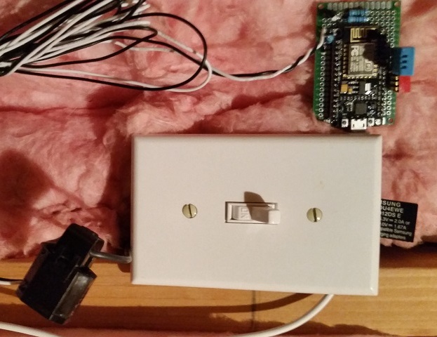
Here is a pic of the first non-breadboard unit - happily reading the current from my attic ventilators. Note I have added a DHT11 for temp and humidity. Still running on a phone charger - batteries nextā€¦

1 Like

Thanks. Have you come across these folk http://crownstone.rocks/