With batteries, just be careful working out if they’ll ever save you money before they wear out (~10,000 cycles).
True, but with a 33% duty cycle needed for this property, would not need nearly as much.
And, if using on the Cosy Octopus tariff with its 3 cheap periods, you can get away with much less. I have 8.5 kWh of battery that just about covers the (oversized) 11 kW heat pump on 3 charges, and by shifting much of the heating into those cheap periods.
1 Like
Good point. I was implicitly assuming a tariff with a single overnight cheap rate period (like Intelligent Octopus Go) where you need to cover 18 hours of ‘peak rate’ - unless you get lucky with an EV charging slot in the daytime. Having multiple, shorter cheap rate periods can greatly reduce the battery capacity required.
That’s just warranty , even though 10,000 cycles is a lot of years even at 1 cycle a day
Hi David,
I have attached the graph for BT25. It looks very strange. No DHW was used and only the master bathroom was heated. I can’t understand why the temperature should vary so much so quickly?
I tried changing the charge pump parameters to 5% to 80 % just to see what would happen. It looks very strange.
I received “the book” today.
Mike
(attachments)
history-export-2.csv (12.5 KB)
history-export-3.csv (2.39 KB)
Hi Mike,
I plotted the data from your ‘history 2’ CSV, which shows BT25 (the External Flow Temp) and yes it’s going higher than I’d expect: up to 45-ish at the top of the peaks. However, we know you’ve got a powerful heat pump and if you’re only heating one bathroom there aren’t many places for the heat to go - so the flow temperature will rise as it attempts to maintain a temperature difference between Flow and Return.
Remember that your heat pump doesn’t know you’re only heating one bathroom. It’s ‘pushing’ heat into the pipework based on its own Weather Compensation algorithm, with an expectation of something on the end of the pipes consuming between about 5 and 12 kW.
On my installation the pumps on all the ‘emitter’ circuits run constantly throughout the heating season, so all the heat coming from the heat pump is being sent to the radiators and the UFH zones (plus a ‘duct radiator’ on my MHVR system to slightly heat the supply air going to bedrooms and reception rooms). That means heat is constantly being ‘dumped’ into the house - very much under the control of the NIBE Weather Compensation algorithm. (The only controls on the emitter side are some zone valves on the UFH loops in a south-facing room with lots of glass that sometimes causes too much passive solar gain, so the floor slab isn’t allowed to go above 25C.)
Personally I find it most useful to look at BT25 (the measured space heating Flow Temperature) in conjunction with:
- S1, the ‘calculated’ Target Flow Temperature
- BT2, the measured heat pump Flow Temperature (seems to be called BT12 instead on ASHPs like yours)
- BT3, the measured heat pump Return Temperature
Here’s an example plot for my system covering three heating cycles, which shows ‘normal’ behaviour for a system which is cycling. BT25 goes from about 24C to about 38C on every cycle.
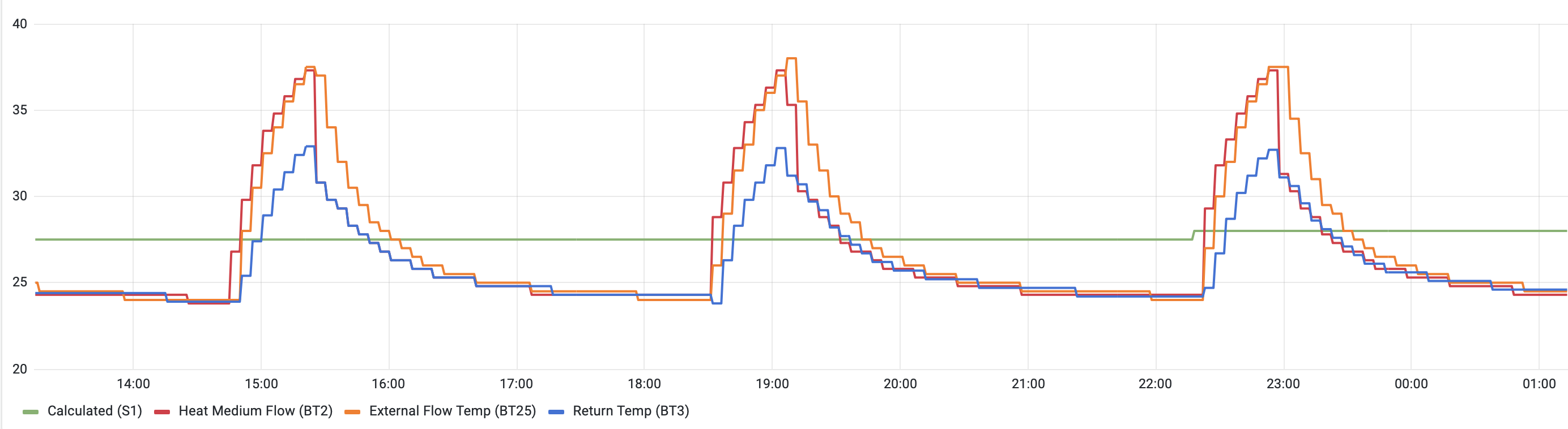
(Note I’ve got an older GSHP which doesn’t have the ability to vary the speed of its compressor, so it has no option but to cycle like this. Mine is an 8kW unit heating 315 square metres. Your more modern 12kW unit will be able to ‘throttle back’ to some extent - down to about 40% is typical - but that’s still about 5kW, going into 150 square metres, so actually you might end up with graphs that look similar.)
Points to note:
-
As BT3 (Blue line; the Return temperature) rises, BT2 (Red line; the Flow temperature) rises too, to maintain a consistent Temperature Difference
-
BT25 (Orange) rises in step with BT2 (Red) but whereas BT2 immediately drops to match BT3 when the compressor stops, BT25 drops a bit more gradually as the Volumiser tank releases its heat
-
S1 is almost constant in this snapshot, just ticking up slightly around 22:15 (probably due to a drop in outside temperature)
-
Overall, BT25 averages out the same as S1 - which is the Degree Minutes algorithm doing its thing
I’m pleased to hear “the book” has arrived. As and when you get chance to make progress reading that I’m hoping the heat pump behaviour you’re seeing will start to make more sense.
David
Hi David,
I think that I am beginning to understand the basic workings of an ASHP system. However, my system is still not doing what I expect. To help me, can you explain how I can
“overlay” the graphs as you did in your last email? I can display any graph I want through “Myuplink” but it is quite difficult to interpret results when moving back and forward between the various graphs.
I’m having problems trying to work the system plumbing. I can’t get to to conform with the NIBE install instructions. I have drawn the system in a simplified form excluding any component that is not part of “normal” flow. I have also excluded the sensors.
There is the BT7 on the top of the tank. (Megacoil)
BT6 in the middle of the Megacoil.
BT 25 on the pipe at the bottom of the UKV40
There is only the 3 way valve. No other valves.
Please have a look at the attached and give me an idea if it looks ok?
I have found some videos by John Cantor on Youtube, so I am working through them.
I hope you had an enjoyable Festive Season.
Mike
Hi Mike,
I’m not aware of any way to do that directly within the myUplink app. Personally I run a small utility script every minute which pulls back the parameter readings using the myUplink API and stores those in a database which I then interrogate using some graphing software which enables the ‘overlay’ functionality for multiple parameters. My background is in enterprise IT systems so I chose to use some fairly ‘heavyweight’ tooling that I happened to have previous experience of but which comes with quite a steep learning curve. For me, it pays dividends because I can combine the myUplink readings with other data sourced from elsewhere - e.g. for the MVHR temperature sensors. I’d be happy to provide further details if you wish but if that sounds like it might be outside your comfort zone you may have more success (or at least good results more quickly) with an alternative approach.
You should be able to achieve the same effect by downloading multiple CSV files covering the same time period then graphing those using a spreadsheet application, if that’s something you’re more familiar with.
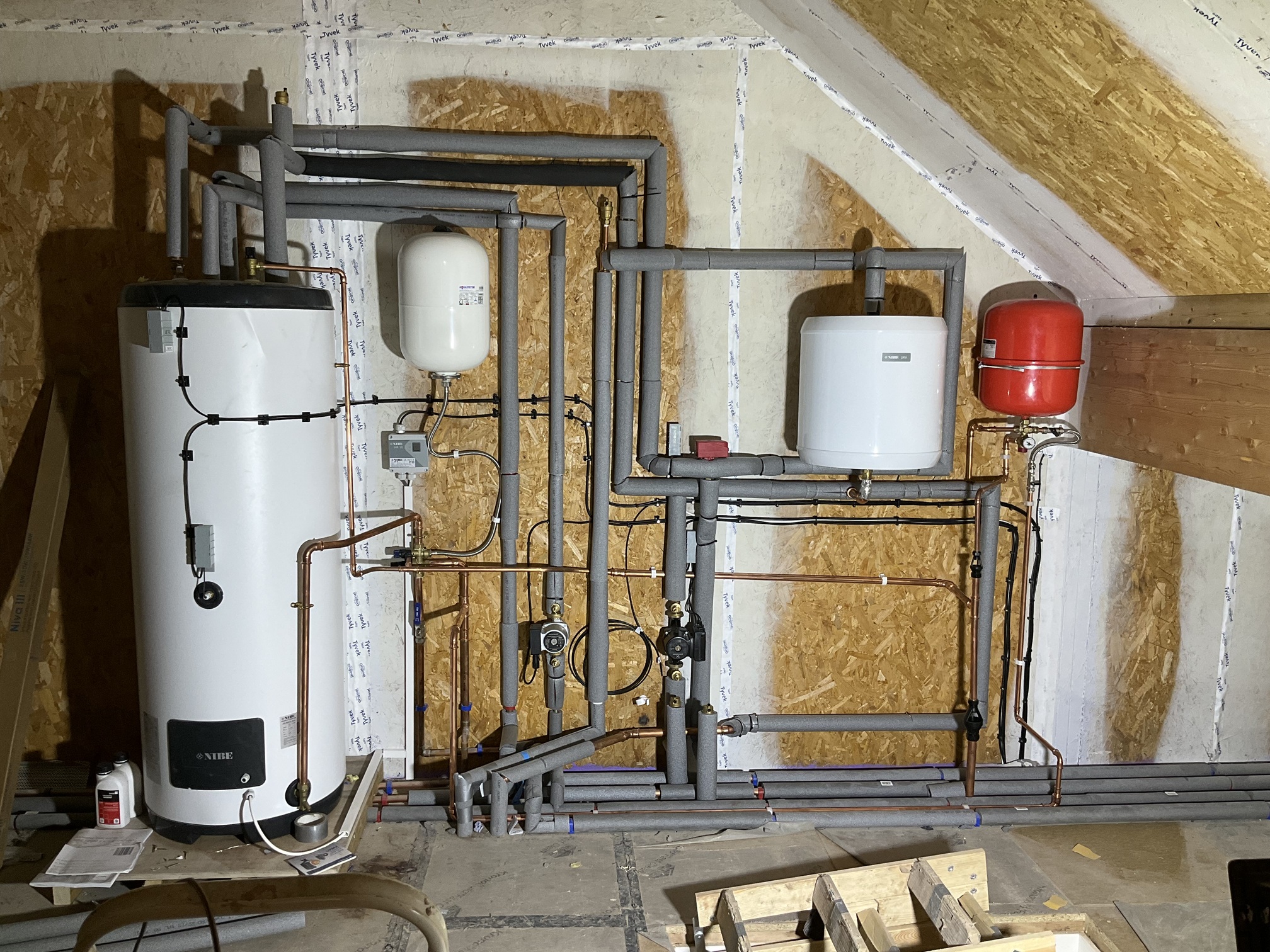
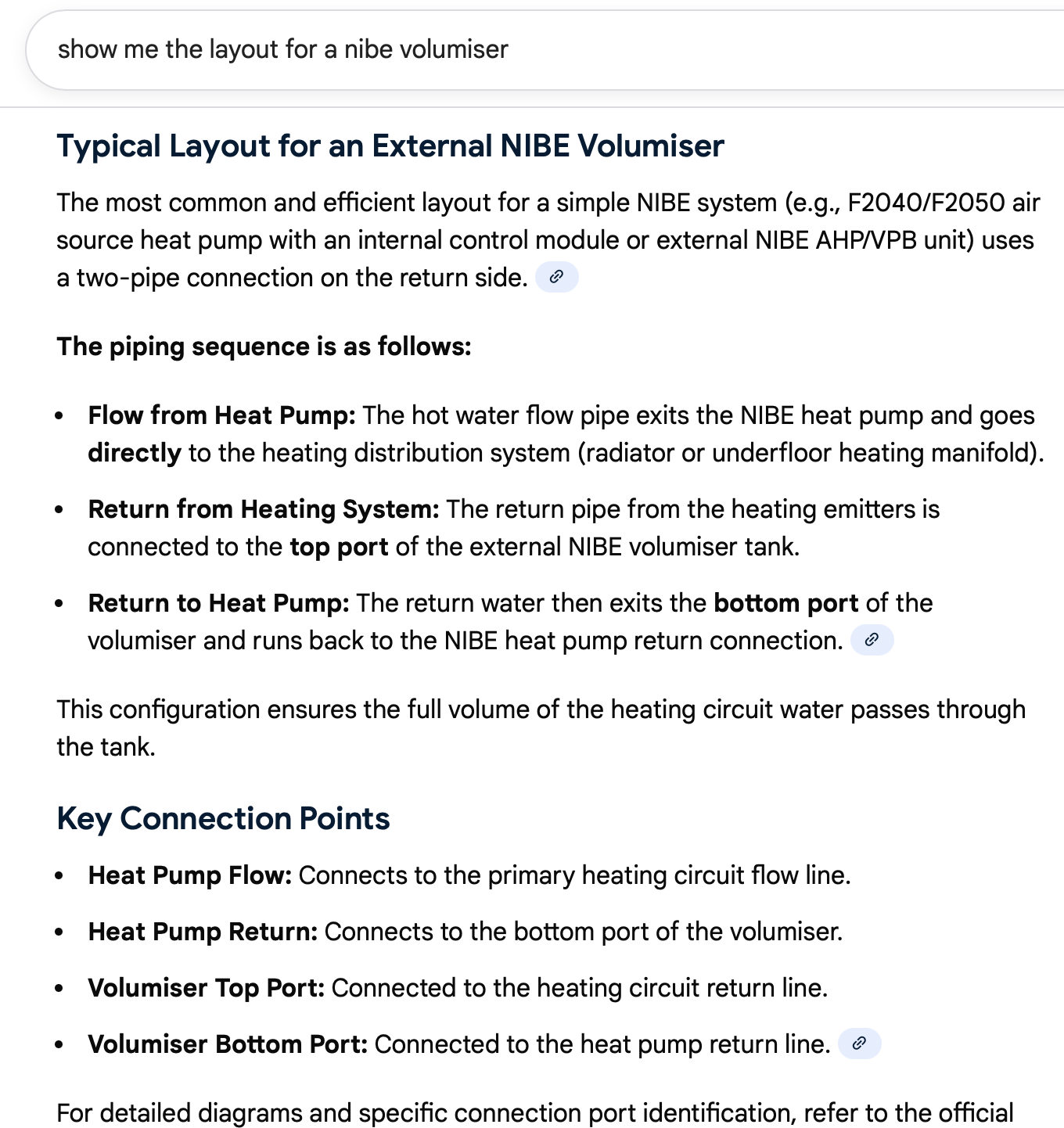
Thanks for the photo. The pipe layout looks clear enough and I can infer a few things about the pipework disappearing into the floor - though not the full picture:
- BT6 in the middle of the Megacoil cylinder is correct - NIBE also refer to that as the ‘control’ sensor for DHW (i.e. the Heat Pump heats the Megacoil until BT6 registers the ‘target’ DHW temperature)
- BT7 at the top of the Megacoil cylinder is also correct - that doesn’t get used for ‘control’ but NIBE say it’s the ‘display’ sensor for DHW
- The Red-topped 3-way Diverter Valve is on the Flow from the Heat Pump, sending that to either the Megacoil DHW cylinder or to the UFH manifolds.
- I generally wouldn’t expect to see any additional Valves, so that’s fine.
- The Black Pump is on the Return to the Heat Pump
- The Silver Pump is a bit more unusual. According to the Megacoil manual that’s on the “Secondary Return” into the DHW cylinder, forming a circuit with the “Hot Outlet”
- Is that for a DHW circulation loop that runs around your house and reduces the time taken to receive hot water at the taps?
- If so, do you know how that pump gets controlled? (I’m just curious… it’s not something I’ve seen before but I know there are different schools of thought on the ‘best’ way to ensure hot water is available when required without losing too much heat into the house)
- The plumbing associated with the UKV Volumiser tank isn’t what I was expecting and I can see why you’d be struggling to match that with the NIBE documentation.
- It looks like the UKV might be connected as a ‘bypass’ between Flow and Return - in which case the placement of the BT25 sensor on the pipe at the bottom of the UKV doesn’t seem right to me (because that’s the ‘Return’ side)
- To be sure, are you able to confirm which pipes connect to the UFH manifolds - is it the ones below the Silver Pump, the left-most pair of insulated pipes going into the floor (with the 90 degree bends a few inches above floor level)?
- Another recent NIBE ASHP thread discussed an installation with a ‘bypass’ Volumiser tank where BT25 (on the ‘Flow’ side) is reading low. That might be worth a read if you’ve not seen it already: Nibe F2040-12kW Please help - quite significant difference between BT12 and BT25 sensors
I had an enjoyable Christmas thanks, although now I’m developing cold-like symptoms which indicate I caught something off one of the younger family members, which might make New Year’s Eve less fun. I trust you had a good time too, if you celebrate at this time of year.
David
Hi David,
One of my sons’ works in IT for, I believe, a French company. Not sure of his actual job since he doesn’t talk about details. I have asked him about combining the charts and he thinks he can help. It will save me having to “learn” another skill!.
I confirm that the Black Pump is GP12 (Charge Pump). I still think that having that pump run while the Heat Pump is shut down, for say, over an hour just results in recirculating cold water in the internal “system”. It really does make sense to try and have the Heat Pump run as much as possible. I don’t think the size of my volumiser justifies GP12 running with the heat pump off?
Yes, the silver pump is the DHW recirculation pump. My installer wired it through the SMO 20 and said I would be able to schedule its run time. Unfortunately, my installer neglected to tell me how to set up the schedule. I spent literally weeks trying to get hold of him to return and show me how the system functioned. I eventually got my electrician to fit a WiFi switch. I was getting fed up listening to the pump (recirculation) running 24/7. Now that I have been able to access the “Service” menu I can see that it would be possible to control it through the "AUX’ menu. Oh well!
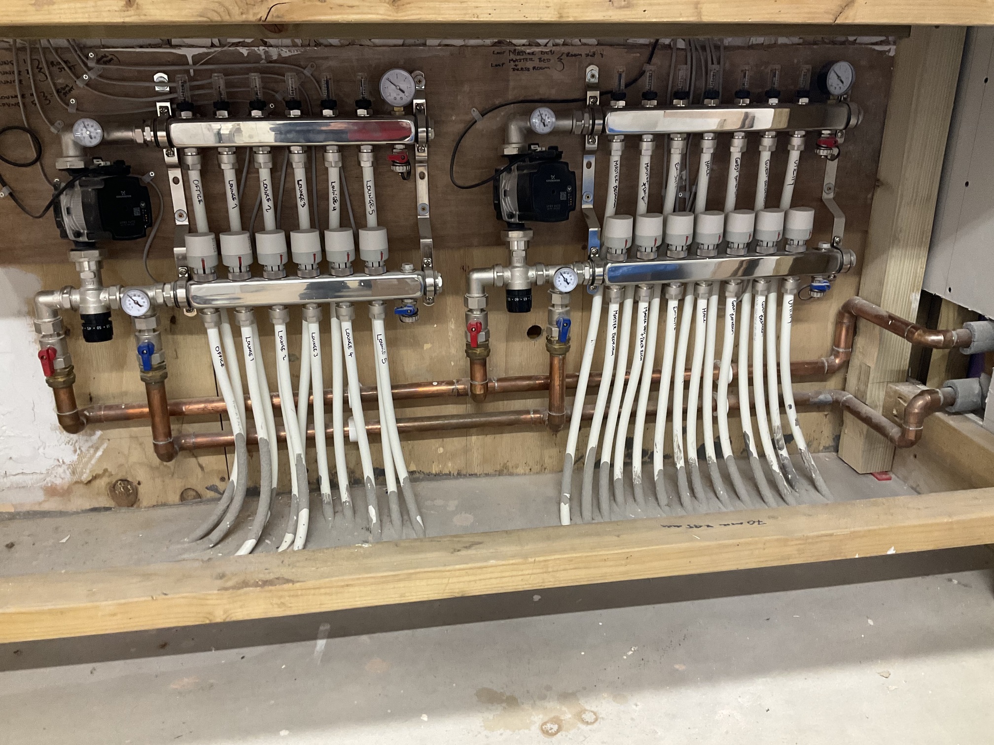
The DHW cylinder and pipework are in the loft. An easily accessible area. I confirm that the pipes going into the floor are the supply and return to the UFH. The attached photo is directly below the pipework. The supply/return are obvious on the right side of the manifolds. The supply temperature is35 - 37C and return, 30 - 32C.
I haven’t had a chance to look at the suggested posting.
Mike
Hi Mike,
If your son is able to help with the charting that will indeed save you some work. I can provide further pointers if they get stuck or have questions.
Running the DHW circulation pump 24x7 certainly isn’t ideal - especially in the Summer when the heat that pipe loop loses to the house is ‘unhelpful’. It’s good that you’ve found a better way to control the pump. I know some people use PIR sensors in Bathrooms to only run the pump when there’s motion that indicates someone might be about to use a hot tap or shower.
Thanks for the photo of the UFH manifolds. Those are the sort of manifolds you’d normally use with a Boiler, having a ‘mixing valve’ (below each pump; silver body with a black knob) which are used to prevent the UFH loops from seeing boiler-temperature water. With a Heat Pump you’re better off lowering the primary flow temperature than mixing in return water at the UFH manifold. It looks like the numbers marked on the valve heads are temperatures and as long as those are set higher than the Heat Pump flow they shouldn’t be ‘mixing’ (but it wouldn’t hurt to set those to their maximum setting).
The UFH manifold layout confirms your UKV is plumbed as a ‘bypass’ between Flow and Return. The biggest red-flag from that is the placement of the BT25 sensor on the bottom (i.e. Return) side of the UKV, where it’s going to see ‘Return’ rather than ‘Flow’ temperatures. You’re going to want to move that sensor to the pipework above the UKV.
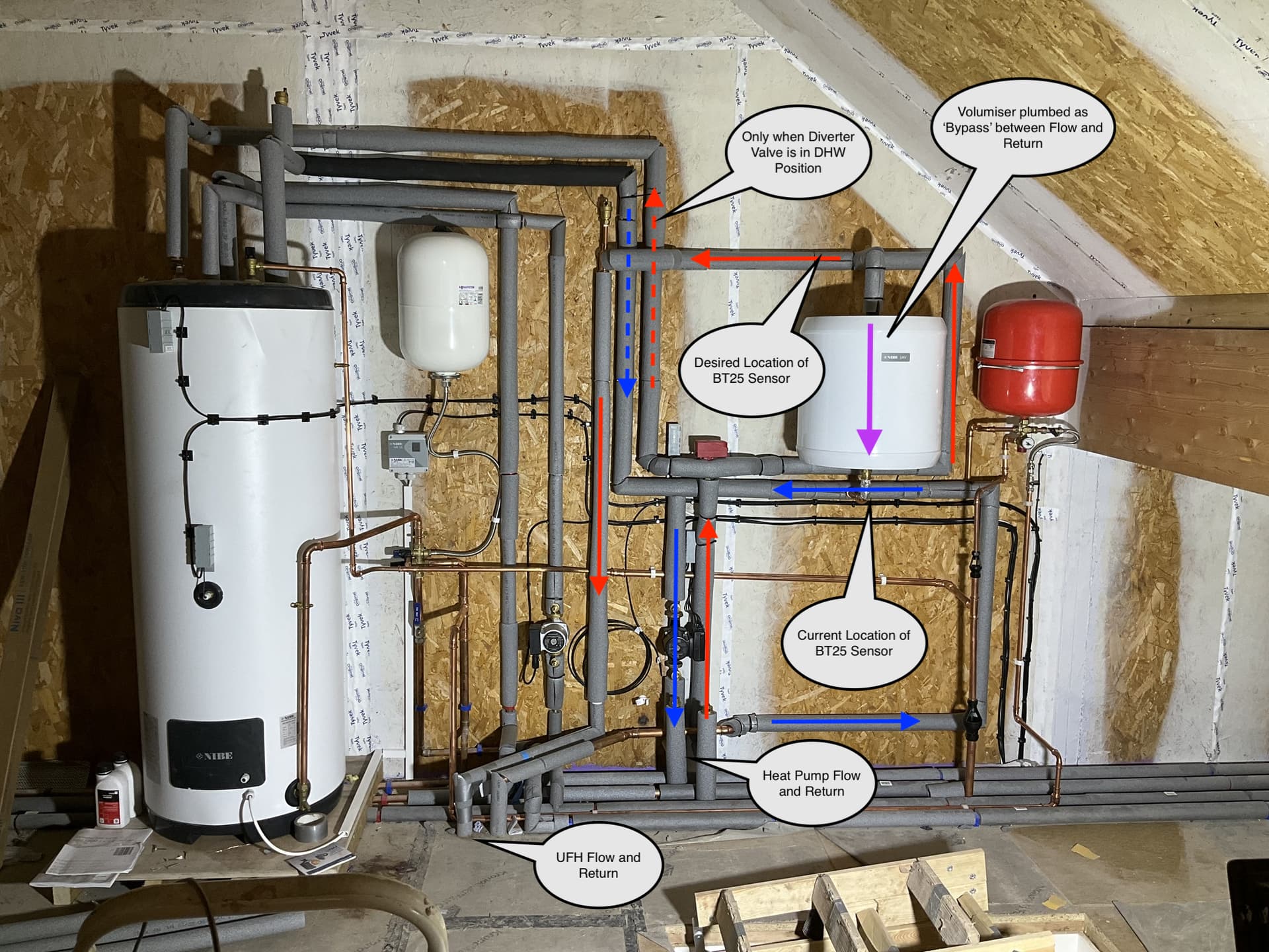
I’ve annotated your ‘loft’ photo with my understanding of the pipework and the preferred location for the BT25 sensor - so it reports exactly what temperature of water is going to the UFH manifolds.
What we’ve seen on some other installations plumbed like this is that if both UFH pumps are running simultaneously they can ‘overtake’ the Charge Pump - with the result that ‘Return’ water flows up through the UKV, reducing the Flow temperature going to the UFH. If that happens - which isn’t ideal - it’s best if BT25 reports the actual temperature.
There are alternative plumbing arrangements which can prevent this ‘reverse flow’, typically consisting of a Low-Loss Header.
My earlier comments about needing to run the Charge Pump (at a low level) even when the Compressor is Off, to empty the Volumiser, assumed it was plumbed ‘in series’. With your system plumbed as is it, I agree you could probably get away with turning off the Charge Pump (GP12) when the Compressor is Off. I’m pretty sure there’s a configuration setting for that - ‘intermittent’ or similar, I think.
1 Like
Hi David,
Great information. I will get some of that “thermal” paste and move the BT25.
The UFH supplier doesn’t seem to understand how a heat pump system should work. After talking to them a little while back I suggested that I set the mixer valve to “max” and let the ASHP deal with the supply temperature. So that is where it is now set.
I am waiting to receive the BUS Grant from my installer. Once I have the money I will be pressuring him to visit my house and explain why he has used this plumbing. He is extremely difficult to deal with and I need the grant.
I have sent 3 graphs to my son (Daniel) to see what he can come up with.
Happy New Year
Mike
Hi Mike,
Happy New Year.
Evidently you’ve already done the right thing with the UFH mixing valves and I completely understand you wanting to secure the grant from the installer before challenging them on the design.
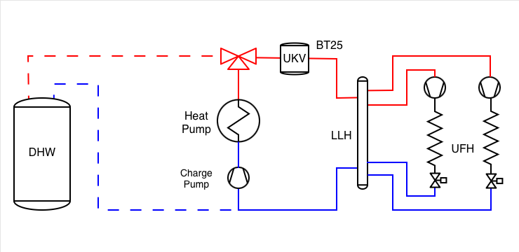
For my own clarity and to make it easier for others looking to contribute to this thread, I’ve sketched a simple schematic of your system. If anything it might be too simple but let’s see. Does it match your own sketch / understanding? Note I’ve not attempted to show the DHW circulation pump / pipework since that’s not relevant to the space heating aspects.
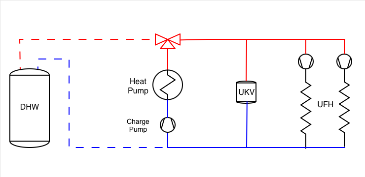
For me, the key thing to consider is what happens to the flow through the UKV Volumiser tank when various circulation pumps are running (or not) - especially since the BT25 “Temperature Sensor, External Supply” is located near there and that provides a key input to the NIBE ‘Degree Minutes’ control algorithm.
If we assume all of the circulation pumps generate the same flow, there’s a problematic scenario when both UFH pumps are running (which would be even worse if the NIBE Charge Pump is not running), shown by the arrows below: the flow through the UKV is upwards, mixing Return water with the Flow on the way to the UFH loops.
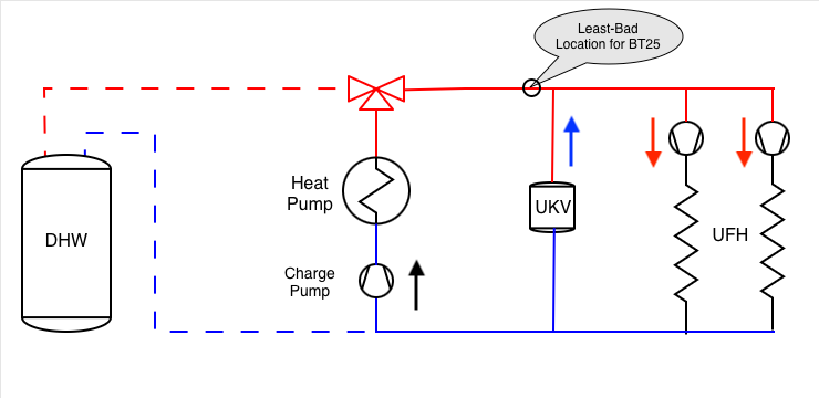
BT25 needs to go near that Tee connection at the top of the UKV, but there are implications for locating it on different ‘legs’ of the Tee. It comes down to whether you want it to see the temperature actually going to the UFH loops or the temperature coming from the Heat Pump. I’m now thinking it would be least-bad to put it on the Diverter Valve side of that Tee (which is different from what I annotated as the “Desired Location” on your photo the other day).
Note that with BT25 located there, if the Charge Pump is not running there will be no flow past BT25 so it won’t provide an accurate reading - which brings us back to why it’s desirable for the Charge Pump to run at low speed even when the Compressor is ‘Off’.
David
Hi David,
Your schematics are completely correct. I have spent a long time trying to work out how the UKV can contribute to the system as it is presently plumbed. I believe that water behaves in a similar fashion to electricity. It will always take the path of least resistance. With the heat pump running it would seem to me that the flow would tend to bypass the junction to the UKV. Continue through the UFH circuit and since there is still pressure in the line on the other side of the vessel the flow would return to the heat pump? The only reason that the supply would enter the UKV from the top is if the pressure at the bottom is lower. Since that return line may have 2 pumps running, even after the UFH circuit, it may result in some of the return flow entering the UKV.
I wrote the above and then found this on a Internet search:
It would seem that the system has not been correctly installed,
Caveat.
The above was AI generated and the installer manual for the UKV40 has different connections, but they don’t seem logical.
Everything that I could find indicated that the flow could be connected in two ways. Supply through the volumiser, or return through the volumiser. In either case the water enters at one end and leaves at the other. So I am looking for superior knowledge.
I have been carrying out some “experiments”. The heat pump is exhibiting peaks and troughs. A rapid rise when the HP (Heat Pump) is on and then a rapid fall once it is switched off. This morning I waited for the HP to switch off. I then disabled ALL the UFH and the charge pump GP12. BT25 only fell 4C in 2.5 hours. I switched on the GP12 (at 10%) and BT25 fell 5C in 8 minutes. It also resulted in a significant rise in BT12 and BT3. This suggests to me that if GP12 is running during the HP shutdown period it will reduce the temperature in the “system”.
I then switched on the UFH. As expected this caused a drop in BT25. What was interesting was that the DM reading had “flat lined” at +100 during the period that the UFH and GP12 were off. It took almost 40 minutes for the DM to fall to -60 (the preset start) before the HP came on again.
Please correct me if I have got it all wrong. The DHW and the UFH are separated by the 3 way valve and the DHW takes precedence. The DHW is set to heat to 45C. This is working perfectly. However, I would like to get the supply temperature for the UFH down to about 35C. This is what I have set for the “Calculated Flow Temperature”. That temperature is displayed on the “Curve”. However (that word again) BT25 is still going up to 44C to 45C with no DHW demand. Could this be the result of the position of the BT25 sensor?
Sorry this post has got a little out of hand. The more I come to terms with the system, the more I seem that I need to know!!
Mike
Hi Mike,
I’ll respond about the Volumiser in a separate reply.
Yep; the 3-Way Diverter Valve is either in the DHW position, sending all the flow to the DHW Cylinder - or it’s in the ‘Heating’ position, sending all the flow towards the UFH. (There are some configuration settings which prevent one or the other from ‘hogging’ all the heat.)
The configuration settings for the DHW and Space Heating operate independently so it’s a coincidence that you’re seeing similar values for the flow temperatures in both cases.
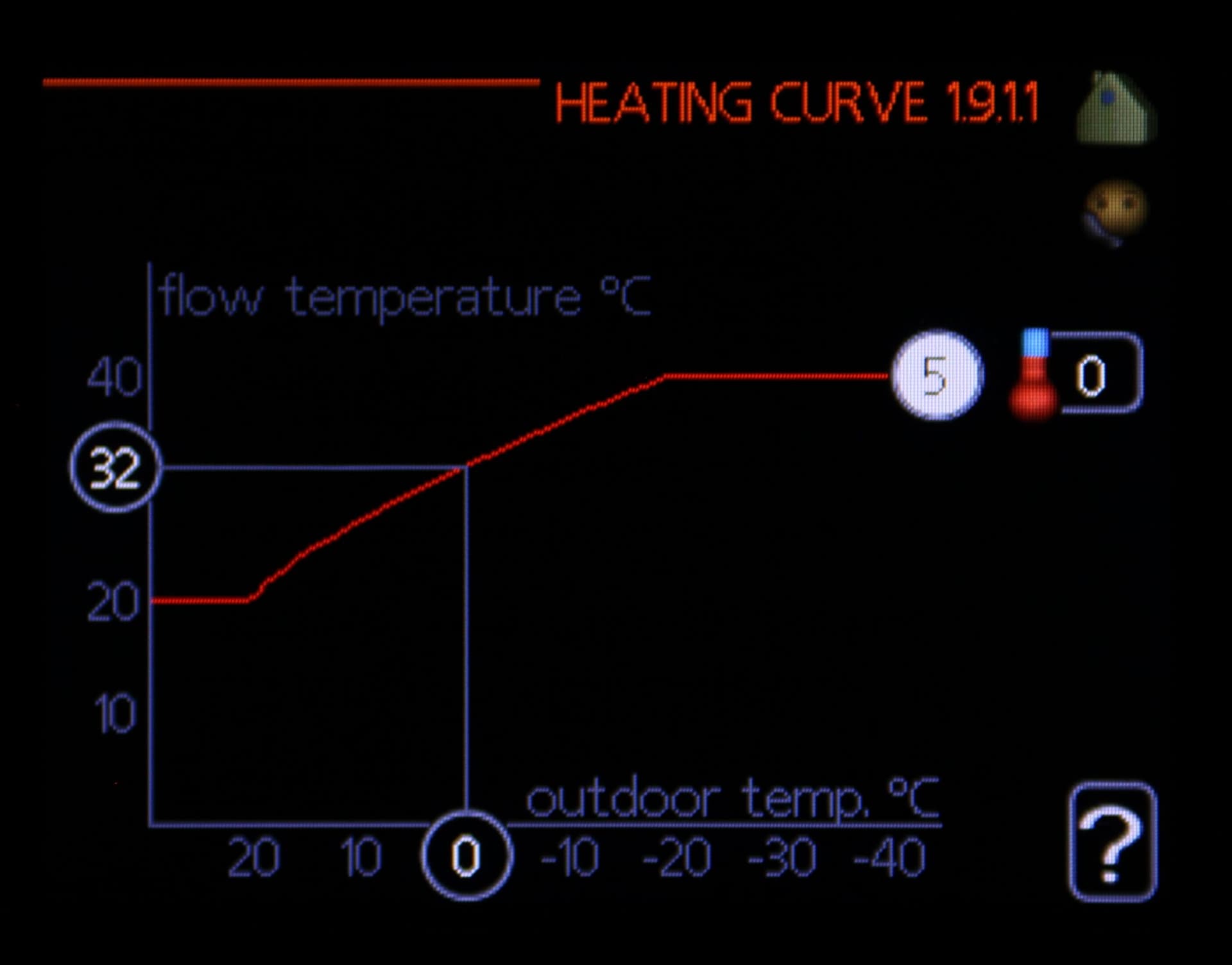
Would you be able to post a photo of your Heating Curve (from Menu 1.9.1.1) please? I’m curious as to which Curve Number you’re on - and what Flow Temperature that specifies for the sort of Outdoor Temperatures we’re experiencing currently. You mentioned you’ve got 35C set for the Flow Temperature but that will only be the case at one Outdoor Temperature.
If it’s not straightforward to get a clear photo just post the Curve Number and any ‘Offset’.
With NIBE systems it’s not unusual for the Flow Temperatures (BT12 and BT25) to peak a few degrees higher than the Target - especially when a heat pump is more powerful than required - as the Degree Minutes algorithm acts to balance out the Peaks and Troughs. However, the more you can do to avoid 40C+ the better for efficiency.
If your installer left you on the Default Curve #9 you should be able to reduce that significantly. I’m on Curve #5, for example.
I’d say the concept of a Weather Compensation ‘Heating Curve’ and the Degree Minutes behaviour are the trickiest bits to get to grips with. Once those concepts - and the way they are presented by the NIBE SMO 20 Controller - start to make sense, all the rest should be relatively plain sailing.
David
Hi Mike,
You’re completely right that water will follow the path of least resistance but that path will often be via the ’short cut’ through the Volumiser. When the UFH is off, the valve actuator heads on each of the UFH zone loops will be closed so there’s no route from Flow to Return at the UFH manifolds - so the only option is for the heat pump Flow to go through the Volumiser and back via the heat pump Return (which does at least maintain a flow through the heat pump; without that it would be very unhappy).
You really want all your UFH zones to be open all the time - although I get the impression your current usage of the property doesn’t need or suit that.
If all the UFH zones are open you’ll have enough water volume ‘in play’ not to need a Volumiser - though during a Defrost cycle it can be beneficial to take heat from the Volumiser rather than from the UFH. The consensus on these forums seems to be that locating the Volumiser ‘in series’ on the Return leg is slightly preferred for Defrosting - although the NIBE manual shows it on the Flow (where it will tend to store more heat, given the higher temperature).
In my view, any system which has multiple secondary circulation pumps (i.e. your two UFH manifold pumps) which are controlled independently from the heat pump is complex enough to benefit from having clear ‘hydraulic separation’ between the heat pump and the emitter circuits, typically using a Low-Loss Header. Including a Volumiser tank (or not) on either the Flow or Return is a separate consideration - so e.g. my system has a 100 litre Volumiser on the Flow, upstream of a Low-Loss Header. Piping a small Volumiser tank as a ‘bypass’ seems like a fudge, in my opinion, since it doesn’t really separate the action of the Charge pump from the UFH pumps.
Note that in other posts on these forums and elsewhere there are references to “Buffer Tanks”, sometimes qualified as a 2-pipe, 3-pipe or 4-pipe Buffer. I find that terminology confusing and prefer to stick with Volumiser (same as a 2-pipe Buffer) and Low-Loss Header (similar in principle to a 4-pipe Buffer).
We’ve not discussed much about your UFH installation and its controls. If you can maintain at least some demand from that all through the heating season (e.g. set one of the zones to a high target temperature) that will keep the water moving and help you choose the best Heating Curve.
David
Hi David,
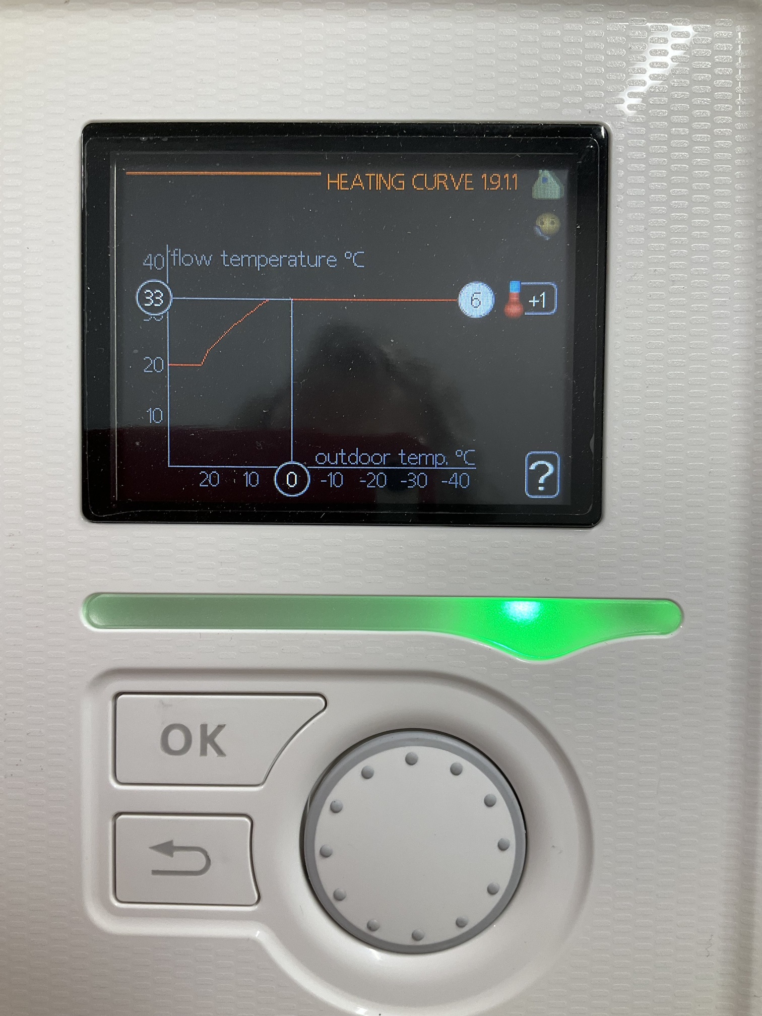
About 4 days ago I started coming to terms with the “Heating Curve”. I now understand the concept. Initially I found that it was set at “15”. I thought to begin with the installer must know what he was doing? I read up the information in John’s book and watched the NIBE heat curve video. I progressively reduced the “curve” first to 9 then 5 with 0 offset. This resulted last night in the house cooling too far. I have now set “6” and a couple of hours later increased the offset to +6. If this works I will increase the curve to 7 and reduce the offset. I have attached a photo of the heat curve before I increased it to “6”
I will be speaking to the UFH company tomorrow to discuss the flow through the loops (13). If I open the valves (increase the thermostat temp) for both the lounge zones (5 loops with a total pipe length of about 450 metres) it seems to “rob” the flow to the other manifold even though there is only one loop in operation. There is one flow pump per manifold. As you can imagine this is not helping with setting up the heat pump supply.
I follow your discussion about the flow with the volumiser, however I am not familiar with a Low-Loss Header.
Mike
Hi Mike,
It’s good that you already have a solid understanding of the Heating Curve and are well on the way to optimising that. I can’t imagine why your installer left it set to Curve 15!
One thing that looks odd in your photo is the maximum Target flow temperature of 33C, which gets imposed whenever it’s colder than about 7C outside. That seems very restrictive to me: basically it’s saying the heat pump should deliver the same heat to the building at -7C (or -17C) outside as at +7C outside, but the heat losses will be very different at those temperatures.
You really want to remain on the ‘slope’ of the curve (rather than the ‘flat top’) for all the reasonably-expected outdoor temperatures at your site, to give the controller some scope to ramp the heating up or down to match the predicted heat loss.
Here’s the equivalent photo for my system. I’m on Curve 5 (where the Target is 32 at 0C outside) but the key point is that the sloping ‘Curve’ continues much further before flat-lining at 40C.
There’s a decent summary of Low-Loss Headers here: Heat Geek: Low Loss Headers Explained - and bear in mind they’re very similar to what John’s book calls a 4-pipe Buffer Tank.
It’s interesting that you mention one UFH manifold tending to ‘rob’ flow from the other. That’s a clear sign that the pipework isn’t allowing each UFH pump a fair share of the flow - or that with 13 UFH loops there’s a demand for more flow than the heat pump (even with the UKV bypass) is able to deliver.
Definitely see what the UFH people recommend but one option would be to change to a pipework layout more like this, where each UFH manifold has a ‘dedicated’ connection to a new LLH (and the Volumiser moves onto the Flow (or the Return) leg).
That’s effectively the configuration I have - though I actually have 3 pairs of ‘tappings’ on the LLH because I have one UFH manifold + one Radiator circuit + one MVHR Heater circuit, each with their own pump and zone valve. I’ve never had any issues with one of them tending to ‘rob’ flow from the others.
Note that the Heat Geek article isn’t a fan of multiple tappings on a LLH but - with a suitable LLH design - I think it can work well, especially just for two UFH manifolds.
David
Hi David,
I spoke to the UFH company. They suggested switching off everything except the master bathroom to check that it stabilized at a reasonable difference between supply and return. It did 32C supply, 26C return. They suggested that the lounge (both zones, 5 loops) had less resistance than the master bathroom loop so a greater flow was being taken by the lounge. I have now switched on about 70% of the UFH and once again the bathroom is not receiving flow ( not maintaining the floor temp) I am going back to them for suggestions.
I have moved the BT25 so that it is on the supply pipe just after the junction with the volumiser. It seems to give more consistent readings in this position.
I have changed my heat curve to the same as yours and will monitor.
The BT25 sensor seems to be giving a reasonable indication of the “system”. Having made the adjustments that we have discussed previously it now looks as though the heating side is cycling between 26 - 28 and 42 - 44 (that is apart from the occasional hiccough - 19.03 today! ). I wish there was a way to run the heat pump at a very low level since it appears to me that it has too much “power” to be able to modulate at say around 800w to 1000w and run continuously. The DM has also remained within tighter limits.
I assume that the unit is just too big for the house. The other problem is the strange plumbing which will have to wait until I can get the Grant:nose:![]() .
.
Mike
Hi Mike,
That does indeed look a bit better. Moving BT25 can only have helped; same with ‘lowering’ the Curve. BT25 is still peaking at 40-ish though which isn’t ideal. Like you say (and as we concluded earlier) it’s delivering more heat than you need, so tending to heat up more quickly than you want. Once you get the rest of the UFH running that should help, since there will be more places for the heat to go.
One further thing to check is the “Compressor Curve” in installer menu 5.1.23. That controls how ‘hard’ the Compressor runs at different outdoor temperatures and you might be able to dial that back a bit, so it’s a little less aggressive Could you post a photo of your current setting there please?
David
Good morning,
Here is the compressor curve. Where would I find information on this parameter?
Mike