Hi All. I am new to the forum. My knowledge of ASHP barely begins to scratch the surface compared to most of the posts that I have read. I hope that if someone can help with my problem it will be in simple terms.
I have almost completed a self build. It has been built close to PH standards for insulation and air tightness. I have an MVHR and a NIBE F2040 pump, SMO 20 controller, UKV 40 volumiser, and a 300L tank with immersion. Wunda fast response UFH. 2 manifolds each with a pump. 13 loops controlled by 9 floor thermostats.
Unfortunately the relationship with my NIBE installer has become very difficult. I want to have some in depth knowledge of the system, but he just keeps telling me that everything is in hand. The Heat Pump appears to be short cycling (on 1 ½ hours off 2 to 3 hours).
My installer omitted to tell me about MyUplink or how to access menus 5.0 and above. I was sure that I was using far too much power. Approximately 20kWh/day but I could check most of the settings. I have now found how to access the data using MyUplink. Now I need help on how to understand the system what all the data means.
Before finding MyUplink I noticed that the charge pump runs 24/7. Now I can confirm it is running continuously between 30% and 80%. The lower rate is when the compressor is off. I have removed the SMO 20 and it appears that the GP12 is not wired as per the Installation Manual. There is only a single black wire connected to -AA2 terminal 7 with nothing on terminals 5 and 6?
The UFH is only heating the master bathroom (22C) and part of the lounge(21C). For a couple of days I reduced the DHW usage to a minimum. Almost no change was noted in the “short cycling”.
My question is where do I start in the system to A. understand the system and B. to fix it.
Any help that the Forum can give would be greatly appreciated. I do not have Home Assistant.
I’ve split this out into a new topic, as your situation seems a little different.
Short cycling is typically more like 10 minutes on, 5 minutes off, so what you’re seeing is something else. Could it be the thermostats turning the heating off?
You might see better performance if the thermostats are set higher, and rely on weather compensation to deliver the right amount of heat.
This does not seem excessive for a 12 kW heat pump. I’m guessing it’s a sizeable property to need one that large, though it’s possible that the heat loss calculations have been over-estimated (a common problem).
It’s good to see another NIBE owner on here. While NIBE systems are nothing like as common (in the UK) as Daikin or Vaillant they’re well-engineered and have robust control algorithms.
I also have a NIBE heat pump (though it’s an older Ground-Source unit) in a Passivhaus with MVHR. Mine’s an 8kW unit which is plenty big enough for 315 square metres of floor area at Passivhaus levels of heat loss. Out of interest, what’s your floor area and what’s the capacity of your F2040? (Tim mentioned 12kW but I wonder if that was inherited from the previous thread.)
For comparison, over the past 24 hours my heat pump used 12.75 kWh of Electricity and delivered 48.725 kWh of Space Heating and 2.65 kWh of DHW Heating - which is what I’ve come to expect, given it was only just above freezing here overnight. If you’re nearly double that Electricity input the implication is that either your efficiency is lower or you’re needing a lot more Heat. myUplink should show you an “Energy Log” which will let you (roughly) calculate your CoP - even without a separate Heat Meter.
I completely agree with Tim that cycle durations measured in hours are not considered ‘short’ and provided you don’t have multiple cycles per hour that’s nothing to be too concerned about by itself.
There’s a thread from a couple of years ago from another F2040 owner in a Passivhaus which might be worth a read: Cost of running a Nibe ASHP , controlled by SMO20 for DHW only. The principal issue there was a two-cylinder DHW setup which led to the space heating drawing heat from the DHW cylinders, which then kept running DHW cycles at high temperatures resulting in very low efficiency. You won’t have that same issue but the discussion might help your understanding of NIBE systems.
That’s completely normal for a NIBE system, with 30% being the factory-default speed in ‘Wait Mode’. The consensus from users on these forums is that a lower speed is generally adequate - 20% or even 10%, which slightly reduces the heat lost via the outdoor unit when the compressor is off. That’s more ‘fine tuning’ than a fundamental configuration requirement though.
Note that the NIBE control algorithm is based on the “Degree Minutes” principle:
The Outdoor Temperature reading is used to calculate the required Target Flow Temperature
In myUplink this is called the “Calculated” supply temperature
The Measured Flow Temperature reading is compared with the Target Flow Temperature and the extent to which the Measured temperature is Above or Below the Target is accounted for in the Degree Minutes running total:
If the Measured temperature was e.g. 3C too low for 2 minutes then 3 x 2 = 6 gets Subtracted from the Degree Minutes
If the Measured temperature was e.g. 2C too high for 5 minutes then 2 x 5 = 10 gets Added to the Degree Minutes
When the Degree Minutes running total drops to -60 (or a different configurable value) the Compressor switches On
When the Degree Minutes running total rises to 0 the Compressor switches Off
If you add both Degree Minutes and the Calculated temperature as Custom Tiles in the myUplink app that should give you more insight into why the compressor is stopping and starting. You might also want to track “External supply line (BT25)” which is what I called the Measured Flow Temperature above.
I must re-emphasise Tim’s comments – that’s not short-cycling. That’s normal operation in mild weather, when the heat demand of the house is below the minimum steady-state output of the heat pump (which is about 40% of maximum output).
Do you have a figure for heat load (kW) at ‘design temperature’? What capacity is your heat pump?
Thank you for your feedback. Perhaps I should add a little background.
I have an F2040 – 12kW
Bungalow with 150m2. High lounge ceiling of 5.5m. Large loft which is ventilated but not heated. Closed to the rest of the house.
Built to (as far as I can tell) PH standards
With the current outside air temperatures only the master bathroom (constantly) and about 40% of the lounge floor area have been heated. The rest of the rooms are remaining above a selected temperature of 19C or 20C. The house is comfortably warm.
5 The UFH is a “fast response” system. Only approximately 8mm of screed over pipes embedded in EPS. There are 13 loops arranged in 9 thermostatically controlled zones. Two separate manifolds supply heat to the zones. The measured in flow temp is 38C and the return is approx. 30C.
I reduced the use of DHW to almost over a period of 2 days. The ASHP continued to operate in the same way, i.e. 1 to 1 ½ hours on and approx. 2 ½ to 3 hours off
I have just checked the DM graph. It is cycling between -80 and -100 up to +100 with a “cycle rate” of about 1 ½ hours.
My own background is 45 years an airline and corporate pilot. As such I am very used to operating complex systems. Is there a training manual that covers the NIBE ASHPs. Not the installation manual. There must be a publication that is issued to installers that attend the NIBE courses?
I have read a lot of the posts related to the F2040 but it is very difficult to understand the way the system is designed to work. It seems that changing one setting in the system can have an undesired effect on another part of the system. I do not want to start “tinkering” without having an overall understanding of the system.
I have only been able to find the DM in the graphs and I could only find “Calculated Supply Climate Solution” not Calculated temperature.
The BT25 is cycling between 28 and 42 every 1 ½ hours. It does vary somewhat in temperature and period.
One function (amidst many) that I cannot work out is why the charge pump runs continuously (variably) even when the ASHP is off. It would seem to me that it will continue to recirculate warm back to the condenser (in a cold environment) in a closed loop. Doesn’t this cause the supply temperature to quickly fall to a point that will again start the ASHP. I follow the theory that it is better to run the ASHP continuously a at low output rather than having it switch on and off. However, if the heating demand, as is the case in my house, is very low doesn’t this result in constant loss of heat via a running charge pump?
I would really like to understand the way this complete system functions. If you have any suggestions how I can study and learn it would me much appreciated.
I must say I’m surprised that a 150 square metre Passivhaus has a 12 kW heat pump installed. The Passivhaus standard specifies a building should need a maximum of 10W of space heating per square metre, i.e. 1.5 kW for 150 square metres - and even that would only be required in cold weather. I would have expected you to have a heat pump rated more like 5 or 6 kW. You’re therefore going to have the heat pump cycling - but my experience is that NIBE heat pumps handle that pretty well.
I’m not aware of any NIBE-specific publications that would cover that content - though you could try contacting NIBE UK to see what they can offer. For an excellent grounding in domestic heat pump heating systems I can thoroughly recommend the book Heat Pumps for the Home by John Cantor which explains the concepts that can then be applied to any manufacturer’s system.
“Calculated Supply Climate Solution” is the parameter you want - the one I referred to as the calculated "Target Flow Temperature”. (Some slightly cryptic translation from the original Swedish I think.) Your flow temperature of 38 seems high - mine is running with a target more like 28 - so it will be interesting to see what target temperature your system has Calculated, based on the Outside Temperature. I suspect you will want to reduce the flow temperature by adjusting the Weather Compensation “Curve” - a concept that is explained in John’s book.
One reason the Charge Pump keeps running when the Compressor is off is to make use of the heat stored in the Volumiser tank. That gets heated up while the Compressor is running but it needs to be cooled down so it can accept more heat on the next cycle, so water needs to be kept moving through the tank, which needs the Charge Pump. There is a trade-off though, since as you noted the water is also being sent back outside and only kept warm by the insulation on the pipework and heat exchanger. So while some flow is beneficial, it doesn’t need to be 30%.
In terms of your UFH controls, you’ll get the best efficiency by running those as “open” as possible and leaving it to the NIBE controller to choose the temperature of the water flowing through the UFH loops. In other words, set the UFH thermostats higher than you really want - something like 23C - so that the UFH pumps are always on and tepid water is always moving through all the UFH loops.
My suspicion is that the default settings left by your installer are running the heat pump rather hotter than is required by your building and (most of) the UFH thermostats aren’t wanting that heat so most of your UFH zone valves are closed. You want the heat pump producing lots of warm water rather a little hot water.
The thinking here is that any heat you’ve paid for electricity to create wants to be delivered to the House (via the UFH) and not wasted. With a boiler-based system you’d have the UFH ‘call for heat’ but with a Heat Pump you want that to be ‘in control’ - and any heat it generates wants to be sent into the UFH. With MVHR it doesn’t matter so much where in the house the heat gets delivered, since all the air gets mixed up anyway.
Hi David,
A huge thanks for your insights. I have immediately ordered John Cantor’s book. My Christmas present to myself!.
I was talked into a 12kW system by the NBE installer. In retrospect I don’t believe he understands the concept of a PH “style” house.
I had always assumed that the thermostats on the UFH would be the primary control, but letting the SMO 20 deal with it is more obvious. I will now start looking at how to configure the various settings. Would the following be appropriate?
DM -60 to +80
Charge pump 10% to 80%. I don’t know how GP12 is being controlled. As far as I can see it is not connected to the correct terminals AA2-X4 5,6,and7.
On the volumiser UKV 40 can you confirm that the supply from the ASHP is to the top and supply to the system (UFH) is from the bottom? It looks as though the BT25 sensor is attached to the bottom pipe with aluminum tape?
Absolutely. DHW heating demand can easily exceed space heating demand in a Passivhaus (especially since DHW is needed all year round) and it’s not unusual for DHW reheat requirements to drive the sizing of the heat pump.
A consequence is that Passivhaus heat pumps tend to report unimpressive SPF figures - because they spend a greater proportion of time heating DHW (at lower efficiency) and lots of time in ‘standby’.
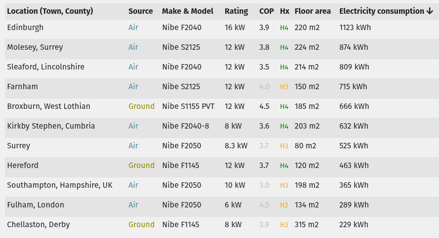
Looking at the “Heatpump + Fabric” view on HeatpumpMonitor, the installations with the lowest Space Heating Heat (kWh/m2) are declared as having Passivhaus levels of insulation but most are barely above 3.0 for SPF - which seems counter-intuitive but still results in very low heating bills.
You’re very welcome. I’m sure you’ll find John’s book easy to understand and very useful. He’s kind enough to contribute to these forums on a regular basis and I’m sure he’d be happy to answer any questions you have about the content.
My reading of the SMO 20 Installer Manual is that the Charge Pump needs two sets of connections from the SMO 20 Controller:
230V L, N, E from AA2 X4:7, X4:6, X4:5
A PWM Speed Control signal from AA2 X2:1 and X2.2
It should work OK wherever the L, N, E connections are picked up from (although I don’t see why anyone would do something different from what the manual says) - as long as the PWM signal is correctly wired; it’s the latter which controls the pump speed.
Dropping the 30% Charge Pump Speed (in ‘wait’ mode) to 10% should be good for your system; I have that set to 20% but I have a larger Volumiser tank and - because I have a Ground Source system - I’m not pumping warm water outside, only around my Plant Room.
In terms of the Degree Minutes settings:
I don’t believe you can influence the DM value for “Stop Compressor” - that’s always set to 0, though as you’ve seen its customary for the DM value to ‘overshoot’ because even without the compressor running there’s residual heat in the heat exchangers which will make its way out (which is why you’re seeing 80-ish as the peak DM value).
As a side note, the controller always limits the reported DM value to not exceed +100
You absolutely can influence the DM value for “Start Compressor”. By default this is set to -60 and if you make it more-negative in Menu 4.9.3 you will get ‘deeper’ cycles with a longer ‘off’ time (waiting for the DMs to get sufficiently negative) and a longer ‘on’ time (as they rise back to zero)
A highly insulated building with a lot of thermal mass won’t cool quickly so can tolerate longer cycles (and so fewer compressor starts) which help to prolong the life of the compressor - although modern heat pumps with variable speed compressor drive motors are much kinder to compressors than the older units (like mine) which are only ever ‘fully on’ or ‘fully off’
You might consider changing the DM setting for “Start Compressor” to a more-negative value. Doubling it to -120 would roughly double the ‘off’ period between cycles
Yes: Supply from the Heat Pump into the Top then the ‘onward’ Flow to the UFH out of the Bottom, as confirmed by this NIBE Document. I have a larger model of UKV (100 litre) which has 4 pipe connections and an integrated ‘pocket’ at the top for the BT25 sensor but it looks like the 40 litre model only has 2 pipe connections hence no room for a ‘pocket’ so strapping the BT25 sensor to one of the pipes is the best you can do. There should be some thermal transfer paste (typically white and sticky) between the sensor and the pipe.
Evidently your installer experience has been pretty poor - both in terms of system design and follow-up support. I suppose Passivhaus is still in its infancy in the UK but a building which needs 90% less space heating than the average house clearly has a big impact on the specification of the heating system (bearing in mind Dan’s comment about DHW heating too).
Hi Dan,
Once I have a greater understanding of the system I would like to use my 300L water tank as an “hot water battery”. Use off peak electricity to heat the water and then use it to feed the UFH. The ability to heat the tank quickly would then be very useful?Mike
Hi David,
More excellent information! I will have a go at changing the settings and keep a careful watch on the effect.
About 10 days ago I installed “Voltaware” to monitor power usage. In theory it can distinguish which units are using power. It is supposed to use some form of “AI” (?) but it lakes about a month to “learn” the system. It does however provide a good way of monitoring total usage. I have Octopus as my power provider with a Smart meter to keep an eye on things.
There are a lot of variables in play but bear in mind the heat pump will be significantly less efficient heating water to e.g. 50C for the DHW tank versus heating it to e.g. 30C for the UFH loops, so storing heat at a higher temperature might not pay off. It depends on your electricity tariff, the air temperature during the off-peak tariff slots (typically colder overnight, so again less efficient - and with more defrost cycles), how much of the 300 litres you typically use for hot water etc. etc. Definitely an interesting topic to investigate though.
Oooh, interesting. I looked at Voltaware a few years ago and would have bought one if they’d been available to purchase. I got the impression they’d stopped making them, never to resume, and had got tired of checking. Please keep us posted with how you find it (in a separate forum thread, perhaps). The principle sounds good - I understand it ‘learns’ what happens to the total power consumption profile when e.g. the Fridge motor turns on so it can isolate the usage from that one appliance without needing a separate sub-meter. I can see how that would work for intermittent loads like a Fridge (or a Heat Pump ) but I’m sceptical about what it can achieve with a whole raft of always-on loads (and I have more of those than I’d ideally like).
I get the impression most of the UK folks on here are Octopus customers of one sort or another. I have an electric car and I’m on the Intelligent Octopus Go tariff. Other people are on Agile which makes for ‘interesting’ optimisations with heat pump scheduling.
Hi David,
I’ve been a bit tied up the last couple of days.
Charge Pump connections : I have rechecked them and the PWM are correct, however they have connected the 230 L,N,E. somewhere else. Is it possible to “see” the charge pump speed on a graph?
My next “project” is to read John Cantor’s book cover to cover. I have no doubt that I will come back with more questions if you will bear with me. In the New Year I will be installing solar and trying to integrate it with the ASHP.
I don’t know the numbers, but it may be more efficient to store electricity and use that to power the heat pump through the day on with a low flow temperature.
Weird. It’s probably fine but possibly there’s a relay switching the Live terminal at the intended connection point, as some sort of ‘isolator’ when the pump is meant to be fully off, which you might be missing out on. (I’d expect the pump to consume a few Watts if it’s getting a Live supply but the PWM signal is 0%.) For peace of mind you might want to look at getting it wired in as per the instruction manual,
Yep; you should be able to add it as a Custom Tile in the myUplink App. For my system the parameter is called Heating medium pump speed (GP1) so yours should be similar; any name containing “pump speed” is probably it.
You will have lots of other things to worry about as you conclude your self build project (especially at this time of year) and there is never any expectation of a quick response from anyone on these forums. As you make progress with your NIBE system you can post back on this thread. If you have more general questions prompted by reading the book those might be better off in separate thread(s).
HI Tim,
That could well be right. It was just an idea that was prompted by some articles that I read. It wou;d probably need a cheap form of power in and a well insulated cylinder.
Mike
That was my first thought too. The challenge is that if the heat pump is using roughly 1kW then that’s roughly 18kWh of battery capacity to cover the peak-rate tariff period, which is a sizeable battery installation just to satisfy the demand from the heat pump - and then it’s tempting to add more battery capacity to cover the rest of the household demand too. The costs for that soon mount up (as my bank balance can testify ).
However, if it means you can cover all your daytime consumption - including all the heating - from charging the batteries overnight (at something like 7p / kWh) then that’s quite appealing - as long as you can fund the up-front investment (and especially if there’s a “summertime” use case for the batteries - perhaps storing on-site generation which exceeds the site export limit, for later use on-site or later export).