All Samsung heat pumps can do cooling. I’ve got a Gen6 R32 Monobloc which can do cooling no problem. However, cooling using radiators is pretty much useless. Fan coils are needed to make cooling worthwhile.
I believe this is what the TDM Plus is designed to address, I believe it provides two separate circulation outputs - one for heating and one to drive wall mounted AC units.
So lets say we are both correct ![]()
Hi @Epic13,
I’m no expert, but judging from your excellent photo, I’d tentatively suggest that your mixing valve is in the wrong place in the circuit, and that this may be part of the problem. At the risk of over-exposing the “standard arrangement” sketch that I produced (with @Robert’s invaluable help), I would expect something like:

It looks like your arrangement has your bathroom/basement UFH feeds F/G coming off before the splitter valve B (which you call mixing valve), and your temperature sensor C is downstream of the mixer rather than upstream.
I would have expected a splitter 3-way valve (if upstream, mixer valve if downstream) on the buffer exit, after the temperature sensor, with flow split 3 ways (1st floor, 2nd floor, bathroom/basement) after (each with their own pumps).
As it is, your mixer valve appears to simply circulate unheated water around your radiator circuit.
I’m happy to be re-educated by the experts on the forum @glyn.hudson?, but it looks to me like you ought to consult another installer…
Sarah
many thanks @SarahH !
so i think that my setup is very close to this one:
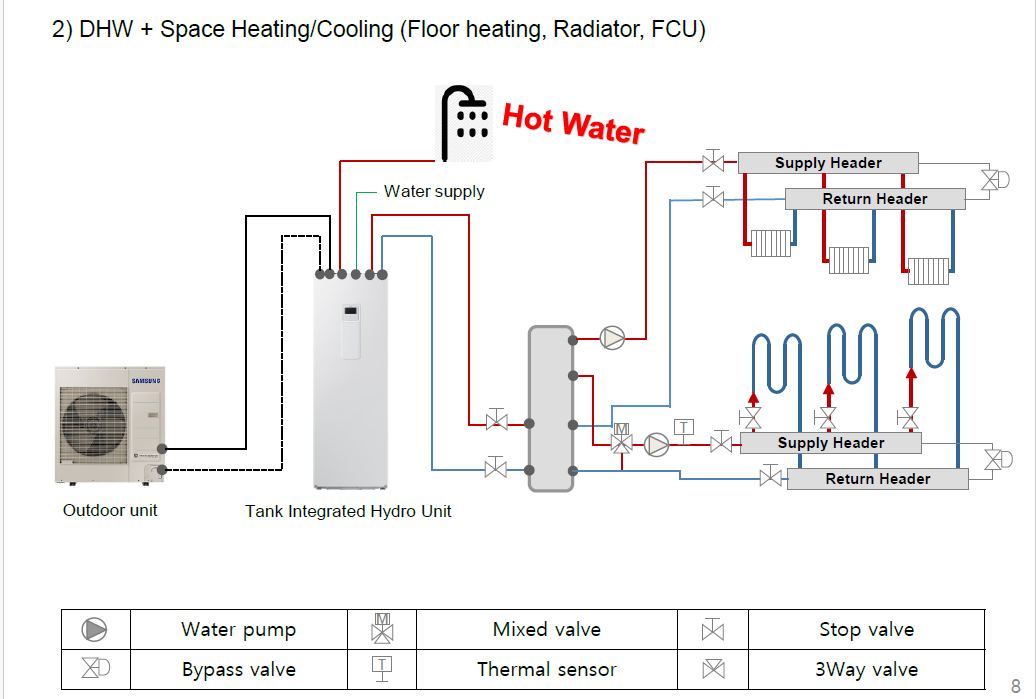
the only difference is that from the buffer we have only 1 hot water out pipe which firstly goes into the radiator/basement circuit (high temp, WL2) and then into the splitter valve where (if high temp circuit is ON) it will bring the floor water to the WL1 set temp.
in the picture from the samsung manual, the 2 circuits get hot water from the buffer at 2 different level.
in my setting bathrooms radiators can work both with high temp or low temp, as the radiator valves call for water pump F. While basement only works with high temp (that circuit is controlled by 2 way valve “H” from basement thermostat.
so not sure if that difference from the buffer is significant.
but mixed valve location seems in line with the samsung schema.
i just can’t get how it is controlled, because to me it doesn’t make sense…
Ah I think I understand more now - I misread your original post.
The UFH circuits have to run cooler than your radiators (temperature limitations on the substrate in which the piping is embedded), so the temperature sensor C controls the UFH supply temperature by mixing hot water from the buffer tank with cool water from the UFH return. (I’ll update my sketch to clarify this.)
I don’t think it matters much that you only have a single flow and return on the buffer tank secondary side provided the flow leaves near the tank top (which it does) so is at its hottest.
Does this help, or have I confused you further ![]() ?
?
Sarah
I can confirm, I own a Samsung Gen7 r290 integrated (AE050CXYBEK/EU), and it supports cooling just fine.
Thanks @SarahH,
this is all clear!
and apologies, but explaining these behaviours is not always easy
.
so my initial question is if anyone has any experience of having the mixing valve closing completely when the compressor turns off (in case of 2091 = 2-4)
as that is causing the behaviours in my 3rd pic above where we have crazy fluctuations of temperatures in the circuits…
anyone who has a similar setting?
as if 2091 = 1, then yes i’m experiencing the LWT raising constantly in the circuit as you were suggesting in one previous post (that if the room thermostats keep being ON).
so i’d really like to set 2091 = 2, but the mixing valve behaviour is basically impeeding me to use that setting…
@Topaz your work on the git you posted is amazing, that is what i’d really like to be able to accomplish (basically seeing all remote controller parameters in home assistant).
the existing integration with Smartthing is only surfacing a tiny fraction of the sensors.
i also loaded a few custom ones, but they only allow to surface a few more, losing those from the original integration.
how would it be possible to know more about how you connected it to your heatpump? i’d be very happy to try it out
Thanks you for you kind word. It took me some effort to make all that. And the list of supported FSV/tweaks is increasing by the day (the snapshot is a bit old already.
About the connection and allowing more people to do so, I’m designing a PCB to connect a USB to the F3/F4 signals (the connection for wired remote controllers). I hope I could ship that in a few weeks (I struggle spending time on this as my prototype full of wires works like a charm).
To make it short, I use a raspberry <–USB–> FTDI 232 <–SERIAL–> THVD8000EVM <–modulated RS485–> F3/F4. It’s only a few wires, the only expensive (and the one reason I’m replacing it) board is the THVD evaluation board. Aside, it’s mainly wires, nothing impossible even for a beginner, just a few dupont wiring.
If you’re willing to give it a go, I can support!
Cheers
Reading your curve, especially the floor temperature, I think your 3way valve is wrongly setup/connected. It swings way too much in temperature. I had this before I fixed it, and now its mainly flat (the EHS open just as required and doesn’t adjust that much afterwards)
@Topaz in your git repo you link to this other work:
here i’m seeing the connection is done with a M5STACK ATOM Lite + M5STACK RS-485 kit Hardware Installation
which seems cheaper overall and i was wondering if that type of connection could work with your setup. I see that work is mainly for AC, but wondering if that way of connecting could actually work for your implementation?
That’s true, but they interface with F1/F2 instead of F3/F4, which is not as versatile if I understand correctly.
My setup is fairly agnostic of the interface, I just don’t know (and have not tested) if the F1/F2 accepts the same packets, I’ll give it a go when it’s not snowing, so that I can connect without freezing ![]()
Yesterday I’ve plugged a FTDI+MAX485 to F1/F2 in parallel of the outdoorunit + control unit (which in my BEK variant are in the outdoor pump).
It works like a charm for logging all values, and I get access to more accurate values such as temperature sensors for air flow, and eev steps, and differenciated power load for compressor/fan/pump etc.
I’ll refine and mae some test to remove the use of the wired controller F3/F4 interface (see if the ambiant temperature are correctly handled after a power outage. Indeed, after power outage when no wired controller was plugged, the ambiant temperature were not retained by the control unit. Maybe it’s working diffrerently from F1/F2.
Also, If that works, I’ll provide with a PCB for interfacing and therefore, it’d be more convenient for anyone to connect (although the FTDI+MAX485 is real simple to setup).
Cheers
I would say that they are pretty similar
- Older versions of the Heat Pumps had a 4-wire interface to the controller, 2 power and 2 signal (RS485 I guess). Certainly Gen 6 now only have a 2-wire interface to the controller, combining power and signal (less things for the installer to get wrong)
- The Modbus interface that Samsung sell connects to F1/F2, and is capable of setting values in the controller, the outdoor unit and the indoor unit. Since the outdoor unit and indoor unit are mains powered F1/F2 can be straight RS485, no need for combined power and signal.
Why don’t you just use a USB<->RS485 standard convertor as others have done? Waveshare seem to be the go-to ones (although other suppliers are available)
@toadhall I agree with you. It’s much more straightforward. However, for ambient temperatures (not targets for zones) I observed it was a bit complex to set, and required many other vars/conditions (much draw power from the F3/F4, must set bit to indicate ambient sensor are present etc) when operated from F3/F4 lines.
And, as you also concluded, the level of information is much less interesting compared to F1/F2. So I’ll make changes in my MQTT bridge to allow for F1/F2 connection, and remove all F3/F4 dependencies.
Cheers
Hi just wondering if you have made up a kit for this, i have a gen 5 samsung heatpump and i would love access to the info shown in your github!
Great work btw.
Even if everything has not been t"sted just yet, I’ve at least understood my FTDI TXDEN pin was not working. And it ended up stalling the RS485 bus due to MAX485 driving using the txden pin.
Also I’d like to check if the “set layer” does support setting the room temps as it’s my main problem.
As a ide note, if I perform a man in the middle rs485 between the outdoor unit and the control kit. I would be able to drive the water out temperature when producing DHW to limit the HP consumption.
Cheers
@topaz Do you know if it is possible to run your python code on the M5Stack or as it is an ESPHOME device does it need something coded in C++ (as you can tell I’m not an expert!)
Honestly I’ve never thought of having it embedded. I don’t know about M5stack. My code is merely a parser and a forge of some NASA commands. It allows to extract intel and configure FSV, all of that through MQTT. that’s it. I wouldn’t say it’s rocket science if at all!
I’m digging theses days to produce an interface board on F3/F4 to USB, so that the code could run on a RPi with a small PCB. So far I have problems with the capacitor not having enough punch for transmission…
Hi @Topaz,
In Monitoring Your Samsung ASHP Controller I outlined one method of accessing the controller inputs/outputs (I/O) on a PC, using a low-cost dongle connected to F1/F2, and the Samsung SNET-Pro2 software.
This approach had the advantage of simplicity, requiring no RPi or coding, nor any knowledge of Modbus/MQTT (whatever they are ![]() ). But SNET is somewhat limited – although it offers the option of changing FSVs remotely, it doesn’t display all the information available at the remote controller (the MWR-WW10N) such as Outdoor Unit power consumption (instantaneous and integrated).
). But SNET is somewhat limited – although it offers the option of changing FSVs remotely, it doesn’t display all the information available at the remote controller (the MWR-WW10N) such as Outdoor Unit power consumption (instantaneous and integrated).
Is it possible for you to summarise what hardware/software you need for the Modbus/MQTT approach, how you go about learning to do the necessary coding, and what controller information you can access as a result? (In the above thread I had anticipated that another user would add this information but I haven’t heard from him since.)
Many thanks…