Definitely, the modbus connection through F1/F2 is definitely easier. However, as you stated, you cannot access everything, and most importantly for my usecase, I couldn’t inject the ambient temperatures of each zone through F1/F2 only via the control layer F3/F4.
The hardware/software needed for
modbus: a computer, the snet software, a dongle to connect the F1/F2 wires to the computer
f3/f4: a computer (or a raspberry (single board computer)), the python script software, a dongle to connect the F3/F4 wires to the computer.
For the modbus connection, you could also replace the snet software with a custom script to connect to something external (MQTT)
Additional details. MQTT is a communication layer to unify internet of things, and to allow for multiple agent to grab those data and process them. I use is linked with Home Assistant (a glorified dashboard for IoT, with scripting/automation capabilities).
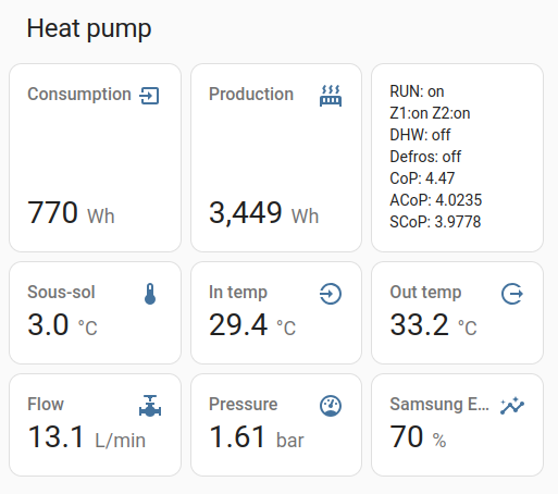
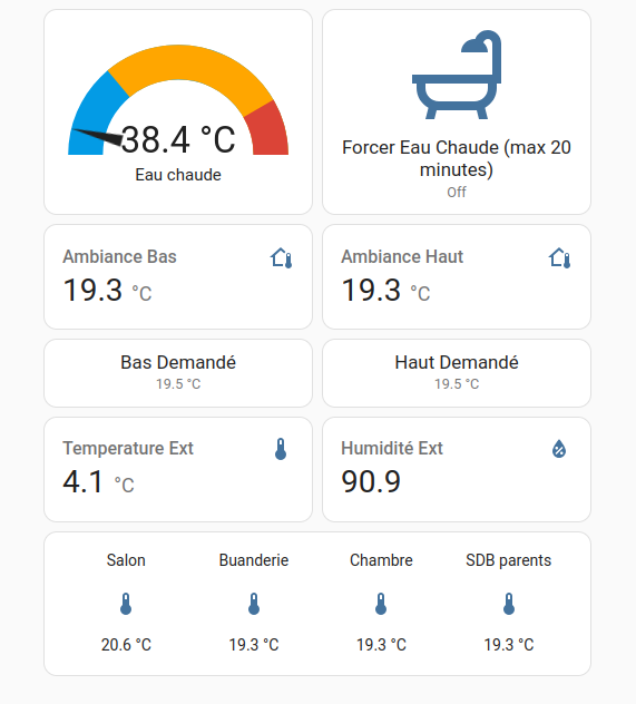
Here are some Home Assistant screenshots of my dashboard :
Many thanks, @Topaz, this looks interesting, but I’m a complete beginner with comms hardware/software, so please be patient with me…
Currently I import data from F1/F2 into my laptop via an RS485-to-ethernet adapter and a virtual port. When I hit “Monitor” on the virtual port I see loads of Hex messages coming in:
I presume these messages represent the various controller inputs/outputs which need to be interpreted for human consumption (at the moment SNET does this, sort of…)
Are you saying that if I install MQTT (I downloaded something called MQTT Explorer today) I can get it to emulate SNET?
Can MQTT record data as well as display it? (I haven’t tried setting it up yet - it looks quite daunting for a layman.)
Also are you saying that additional information is available at F3/F4 (like “EHS Input Power” which I see on your HA output, but which SNET doesn’t display)?
If I do need to switch to F3/F4 to get at this extra data, can I simply reconnect my existing RS485 adapter?
What does Home Assistant do that MQTT doesn’t? HA costs money and I don’t want to spend £100 on something I don’t need for anything else (we run a really low tech house - I don’t even own a smartphone…) If I do need something with HA’s capability, do you know of a lower cost equivalent?
HA is mainly a frontend of presentation of recorded data,
MQTT is just a virtual link to convey data from a source (rs485 interpreter, f3/f4 interface) to a sink (HA or whatever).
The main goal of HA is to allow for interaction made easy with the heatpump. It can run on the same host as you would run SNET. and it does record only for about 14 days or so (configurable, but it’s a very fat encoding), I usually install another tool to record longterm (influxdb).
I’m not sure transitioning from F1/F2 (RS485) to F3/F4 (modulated RS485) would be of any use if you already have all your usecase covered with the F1/F2 link.
Cheers
The only data I wanted that SNET-Pro2 doesn’t give me (from F1/F2) is the Outdoor Unit power consumption, and though this is available on the remote controller display, I can’t log it.
I guess I’ll just have to correlate Compressor Current (which I can log) against Outdoor Unit power consumption (seems to be roughly power (kW) = 0.42 x current (A) + 0.2) and stay away from F3/F4…
Dear Sarah,
If I’m not mistaken, I’ve found the total consumption in the F1/F2 communication, It’s issued from the CT1:
[0x8217, “VAR_OUT_SENSOR_COMPRESSOR_CT1”],
[0x8278, “VAR_OUT_SENSOR_OCT1”],
Check one of those, it should then be multiplied by 0.1 and to your local grid voltage.
Hope that helps, and clearly, it’s overkill to adopt a new data access chain just for one value!
Have fun
I don’t know how to access the 0xnnnn codes directly, but SNET-Pro2 displays an entry “OCT1” which I never understood, but if this is “Outdoor Current Transformer 1” as you hint in your post, then I can indeed get the data I’m looking for. I’ll fire up SNET tomorrow and see if it now makes sense…
My only question is, where does the 0.1 in your post come from?
Indeed it sounds like you get your intel there!
The 0.1 is because the value is expressed with a unit of 0.1A if I remember correctly.
I pray that this solves your problem.
Regards,
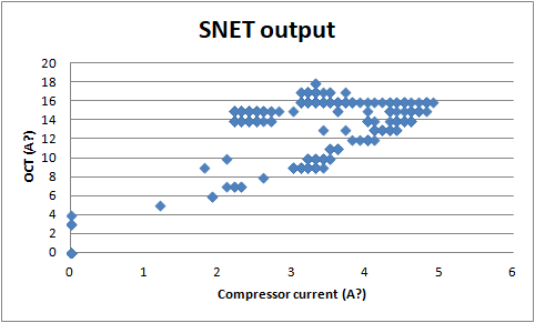
Unhappily, @Topaz, the “OCT” reported by SNET (supposedly, related to Outdoor Unit power consumption via grid voltage) bears little if any relation to the power consumption displayed on the remote controller.
Take a look at this plot of reported Compressor Current vs OCT (without your 0.1 factor, gathered over about 90minutes, during which time the compressor inverter varied 20-50Hz and the calculated heat output varied 4kW-10kW):
I have a question for @billt and/or @glyn.hudson.
I have bought the MRW-TA kit, fitted it and plugged it into the ROOM socket on the MIM board. How do I “activate” the new sensor? The display on the wired controller is still showing the temperature of the thermistor in the wired controller not the new remote thermistor.
For reference #2091 and #2092 are set to “NOT USE” and #2093 set to “Room Temp ON/OFF or WL Interlink ON/OFF (Water Pump3)”
I do not have a separate thermostat, the system is controlled the wired controller.
I’ve added an ‘@’ in front of Billt and Glyn’s names to convert them to what we call ‘at’-references. This way, they (particularly Glyn) will get notified of your question.
It’s a long time since I did it, but I think the steps are -
enter Service mode > Indoor Zone Options > Temp sensor selector.
You can toggle between local and remote sensors there.
Hi @billt
Thanks for your reply. Your suggestion has partially worked. The temperature displayed on the wired controller has changed from displaying that of the internal thermistor to a fixed reading of 20.0 C. Heating or cooling the new external thermistor doesn’t change the reading. This is the same problem you commented about on a different forum approximately a year ago. Unfortunately solution was given.
How do I get the actual temperature of the external thermistor to be displayed, rather than the fixed 20.0 C?
.
I’m slightly out of my depth here, @SteveSpanners but I think that your MRW-TA counts as an “External Room Thermister” for the purposes of FSV settings, and as such, you should set FSV #2091 (or #2092, depending on whether you are using WL#1 or WL#2) to your preferred setting. Once done, FSV #2093 (which uses the wired remote controller) will be ignored.
I use a 3rd party (Honeywell) roomstat (i.e. I use #2091 rather than #2093), and I haven’t yet been able to see the current roomstat measurement indicated on the remote controller - all I see is a default 20degC. I assume that this is because the Honeywell doesn’t transmit the measured temperature, it only transmits “demand” or “no demand” signals into the MIM controller in accordance with its thermostat setting. (In the case of the Honeywell these are (variable cyclic) TPI signals, but the MRW-TA is most probably simply on-off.)
So unless you can discover a way of getting your remote controller to interpret and display the MRW-TA signals, you just can’t do this .
The MRW-TA is just a thermistor which replaces the thermistor in the wired remote. It isn’t an external thermostat so 2091 and 2092 should stay off. 2093 is set to 3 in my installation.
Sorry, I’ve run out of ideas and don’t remember what else I may have done.
(The remote thermistor does report room temperature to the controller and it is displayed on the remote and can be extracted with an RS485 interface.)
I have measured the resistance of the thermistor in the wired remote controller and the MRW-TA and they have similar characteristics. This supports what billt is saying, and contradicts SarahH saying it is an on/off device.
My understanding also agrees with billt that 2091 and 2092 should be OFF.
2093 is currently set to “Room Temp ON/OFF or WL Interlink ON/OFF (Water Pump3)”, I think I need to do some experimenting.
If I can’t find a “proper” solution, I think I will connect the MRW-TA directly to the wired remote controller by cutting out the existing thermistor and soldering the leads from the new remote thermistor in instead.
The MRW-TA kit appears to be normally used on aircon units, and the instructions supplied mention turning switch K1 off. I have tried turning off switch 1 of the red switch block on the MIM board, but it didn’t help.
I will investigate further and report back if I find a solution.
Thanks again.
Very interesting topic that help me to understand and troubleshoot my Heatpump high energy consumption problem.
My Samsung Heatpump is 2015 gen ( AE160JXYDGH/EU ) with Samsung wired remote controller including 2 Nest thermostats for downstairs and upstairs - upgraded from the analog ones that the installer provided with the installation.
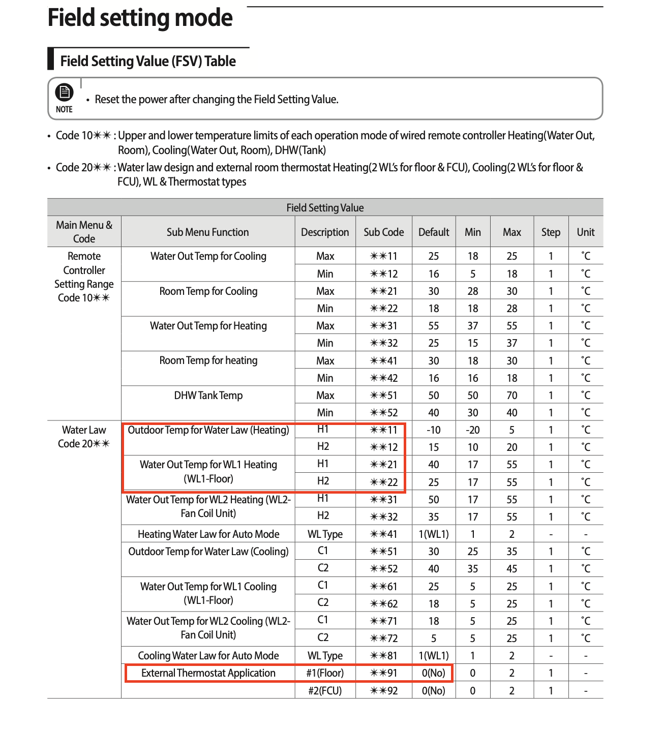
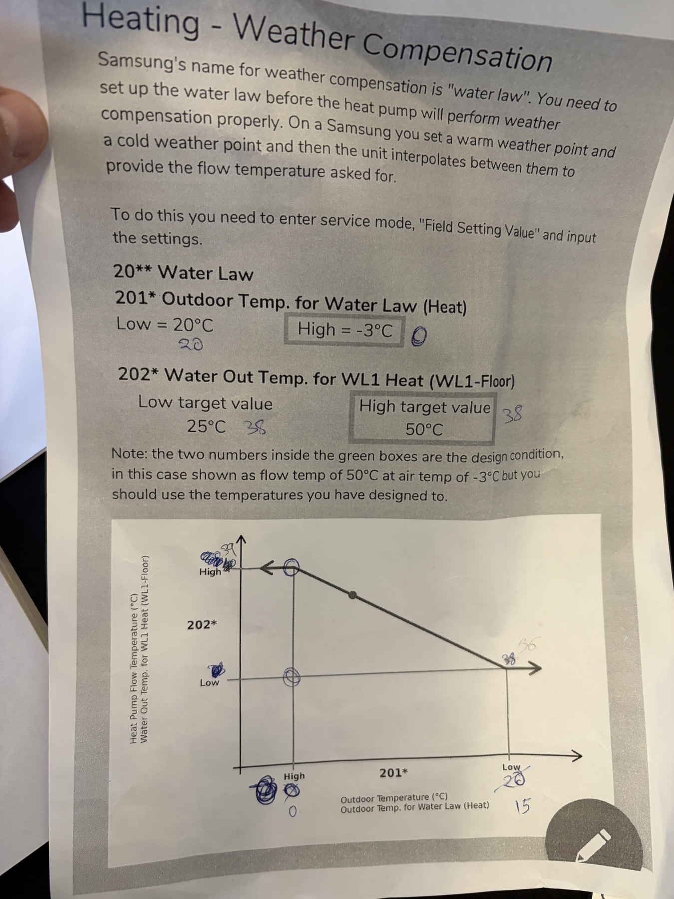
Over the years the settings was 2091 to 1 and 2092 to 0 meaning that weather compensation was not used. After reading this thread I changed the settings and I have set the H1 & H2 of 2011(0) 2012(15) 2021(39) 2022(36).
Which Point to use:
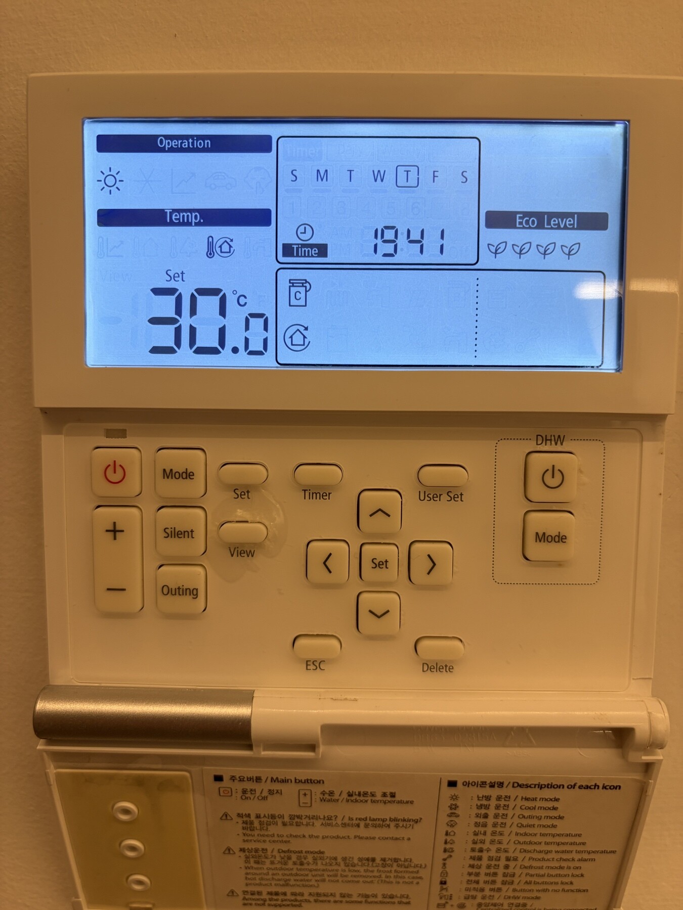
( A ) I have set in the wired Samsung thermostat 30c assuming that is now the target temp 30c but what I did not understand, this value overrides the H1 & H2 of the 2021 OR 2022 ?
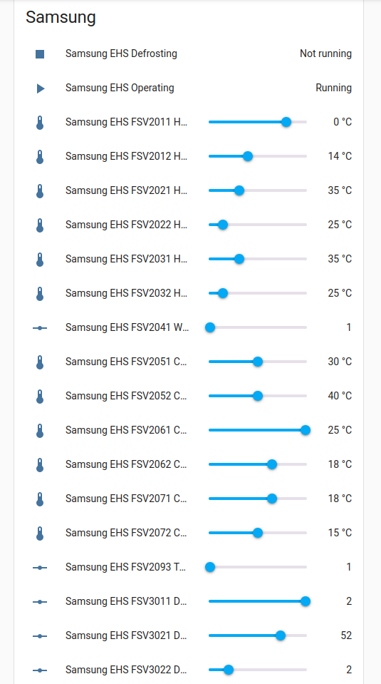
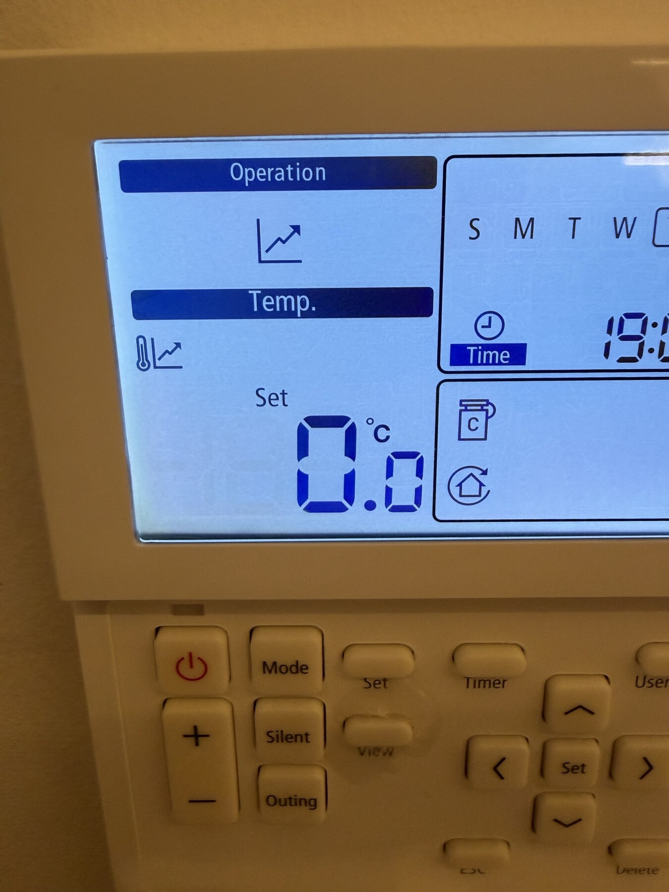
(B ) Changing the mode to shift up down the target temp by -5 / + 5 this setting overrides the previous mode ? leaving the value to 0.0 what is the target temp ? 39c based on 2021 setting? - see the attached diagram photo.
I’m a bit confused which of the 2 to use A or B
At this stage I’m doing my tests without changing the third party thermostat schedule only by interrupting the point A temp. What I see is now the Heatpump uses the inverter than before, it was running all time full power consuming over the years a lot of energy. In the cold days with estimated 8-10 hours running consumed sometimes 45khw. Please not that I have solar system with Primary Smartmeter and for all the house monitoring the consumption and Secondary smart meter only for the three phase Heatpump which I can monitor the Amps voltage etc.
Going to the technical part I found out that when I enabled the 2091 setting always one of the Valves(Siemens) must be opened to circulate the water to keep it to the target temp, which is logic. How can I change the setting to keep both Valves always open and not only the one; because if the one of the circuit closed then the water loose temp until the next schedule point of the third party thermostat trigger the valve to open to heat based on target set point.
Hello @HeatpumpCy and a warm welcome to the forum.
If you set either#2091 or #2092 to something other than zero, any setting on #2093 (which sets the roomstat in the Samsung Wired Remote Controller - WRC) will be ignored, and only your selected remote roomstat (your Nest) will be used for Water Law (weather compensation). So in your point (A) it doesn’t matter what you set the WRC to.
You have marked your #2011/2/21/2 settings correctly on your photo. This is your target LWT for any given ambient temperature, and the heat pump will try to achieve this using its own internal control algorithms. The lower this target, the lower will be your power consumption.
Your WRC gives you the provision - using the +5/-5 function - to move this target up or down a little (i.e. the graph in your photo moves vertically up or down by up to 5degC). You might find this useful to temporarily change your LWT if, say, you find that you need a boost to emitter temperatures if you find that a strong wind blowing from a particular direction increases your house heat loss. This avoids the need to reprogramme your FSVs every time.
45kWh/day is a lot for a house in Cyprus, even a large one, and you are right to expect something lower.
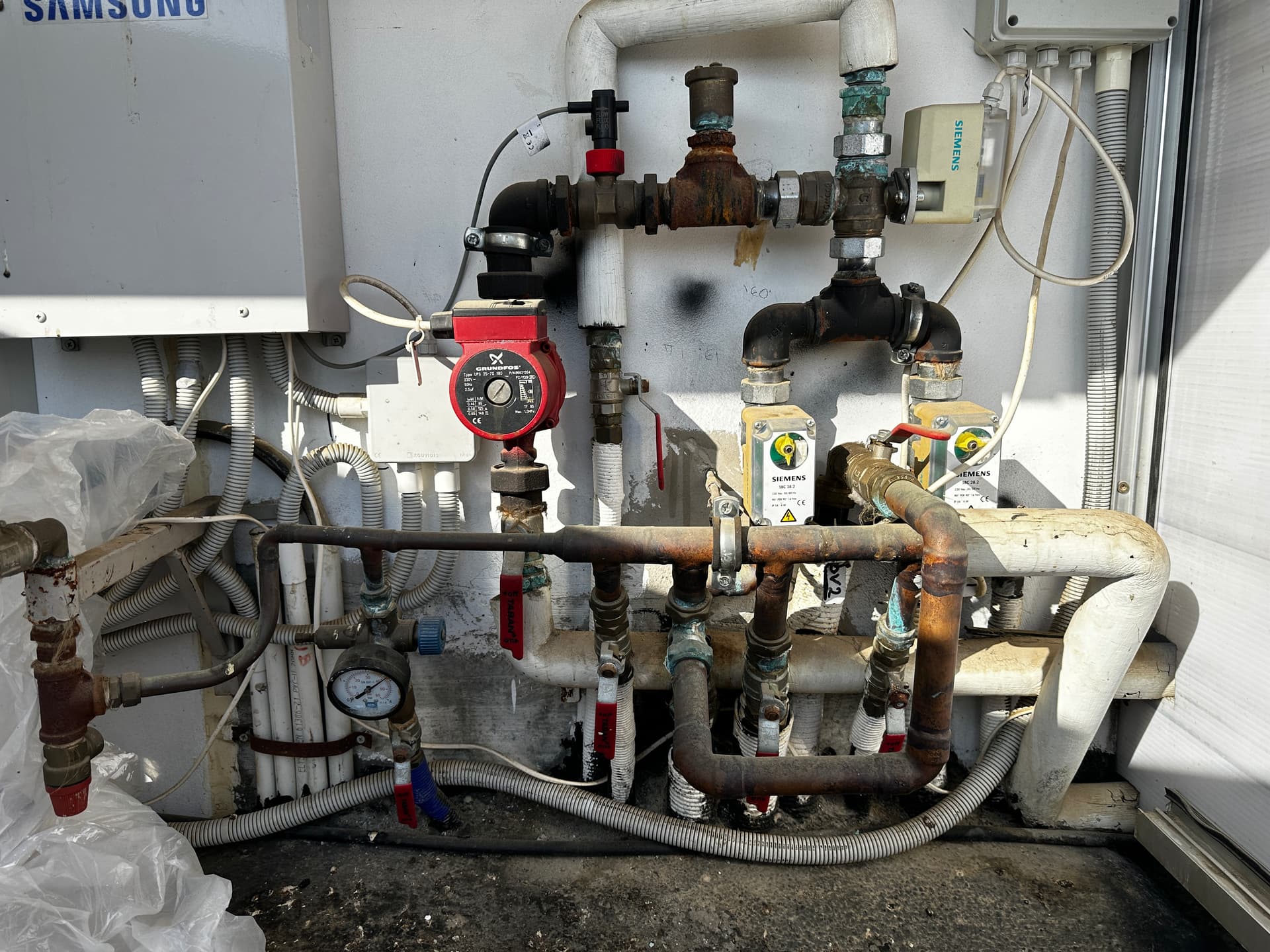
Can you clarify your description of your valving arrangement (e.g. a sketch)? When you say 2 Siemens valves are you referring to DHW and space heating or something else? Normally, the heat pump feeds either DHW or emitters, not both simultaneously.
PS I have promoted you so that you can post several images (or PM other users).
I don’t have the option #2093, this applies to a newer SAM WRC? My NEST don’t apply whether compensation just on/off. (UK Version )
To make it more clear, the +5/-5 function interfere with the FSV 2021 & 2022 predefined settings which are currently 39 & 36 right ? – based on photo I provided before
Yes too much consumption, unacceptable!!! I manage yesterday to keep the consumption to 23khw setting the Set temp to 30c but the house dropped in 24h 1C. To accomplish 22c indoor I changed the Set temp to 35C, and consumed 27khw in 8 hours. Right now I moved it to 40C to see how it will go and I will see tomorrow if is more efficient.
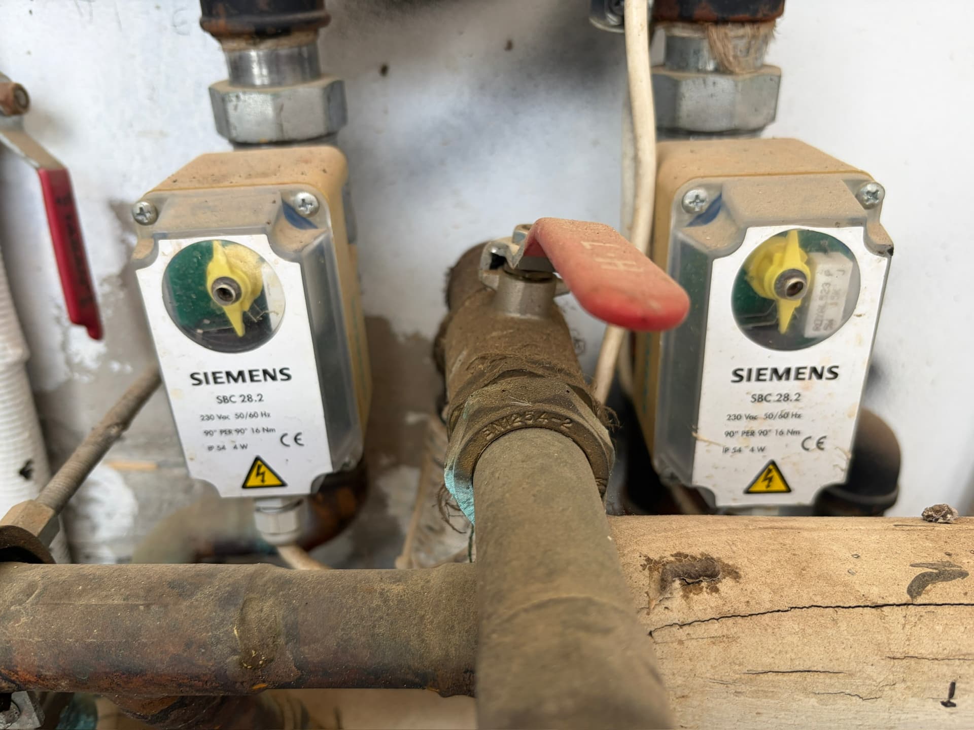
I’m not clear what is space heating yet. My house has 2 zones. Upstairs and Downstairs + the 3 way valve that goes to DHW(boiler, not samsung). I can heat each floor independently with different temps using the on/off thermostats (left Siemens Downstairs, Right Upstairs )
When my heat pump heat the DHW 3way open but Upstair valve/siemens close. Downstairs keeps running normal. When the WRC/Timer finish the heating of the hot water(boiler), Upstairs Siemens automatically open to continue to heat.I have separate manifolds for each floor.
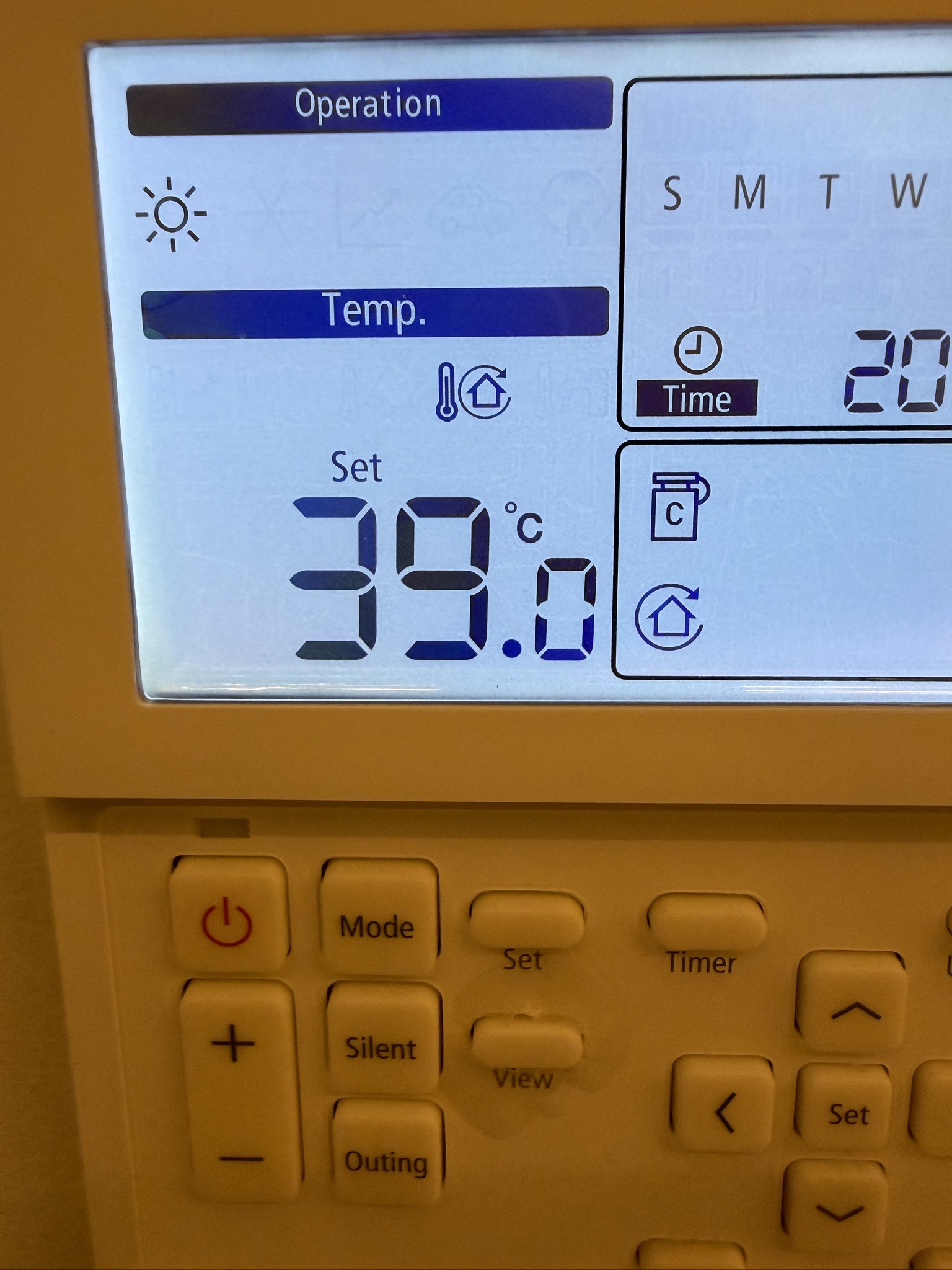
I’ve notice that Discharge Water set temp is reached after some time but when the Heatpump stop heating because achieve the set target then the temperature from 39c drops to 36c and then start heating again, inverter works 1200watt - 1800 watt 2300 watt etc base how close is the set target.
What cause the water to drop so much ? is that normal ?
Set temp 39c revised from 40c as per my previous posts