STM32 Hardware Development

In the interest of a public discussion for those interested, we’ve been discussing STM32 hardware configurations in a PM.

Early on in the thread Robert Wall posted

Paul Burnell then replied (excerpt from the post):

I mentioned my wish to have a MBUS reader module to integrate heatpump monitor development efforts and the option to directly mount a RaspberryPi3.

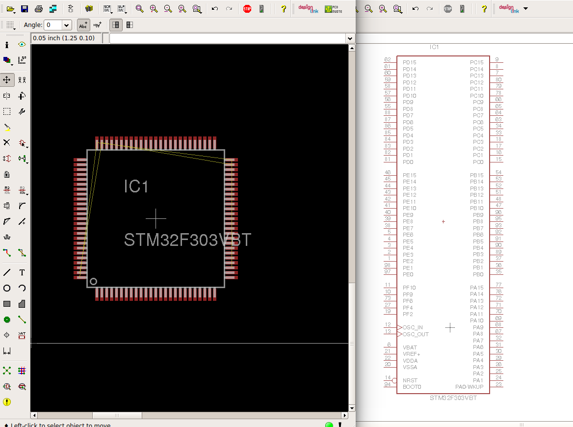
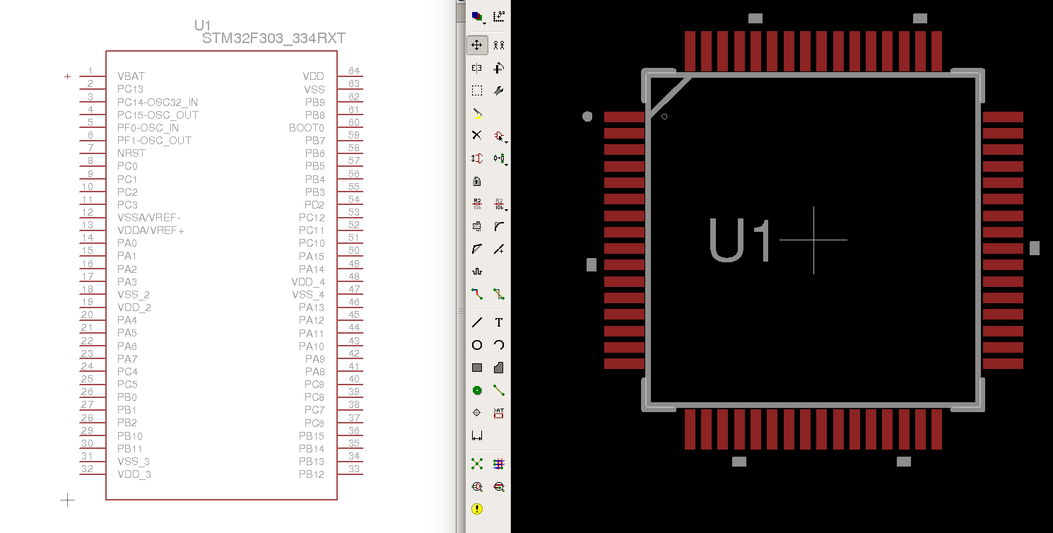
Later on Paul asked the question in relation to discussion regarding 64 vs 144 pin stm32f303 package:

I made a list of the main options I could think about:

  • Single phase, whole house: 1V + 1CT
  • Single phase, solar: 1V + 2CT
  • Single phase, solar, EV, heat pump, import/export: 1V + 4CT
  • Single phase, total number of used circuits in my distribution board: 1V + 7CT’s
  • Three phase, whole house: 3V + 3CT
  • Three phase, solar: 3 + 6CT
  • Three phase, solar, EV, heat pump, import/export: 3V + 12CT

Paul then replied with an extended discussion, targeting 15-18CT’s:

Paul and Robert reinforced the point that the solution needs to be modular.

We discussed a little on enclosures, the need to find an enclosure approach that could accommodate a potentially modular + stackable approach.

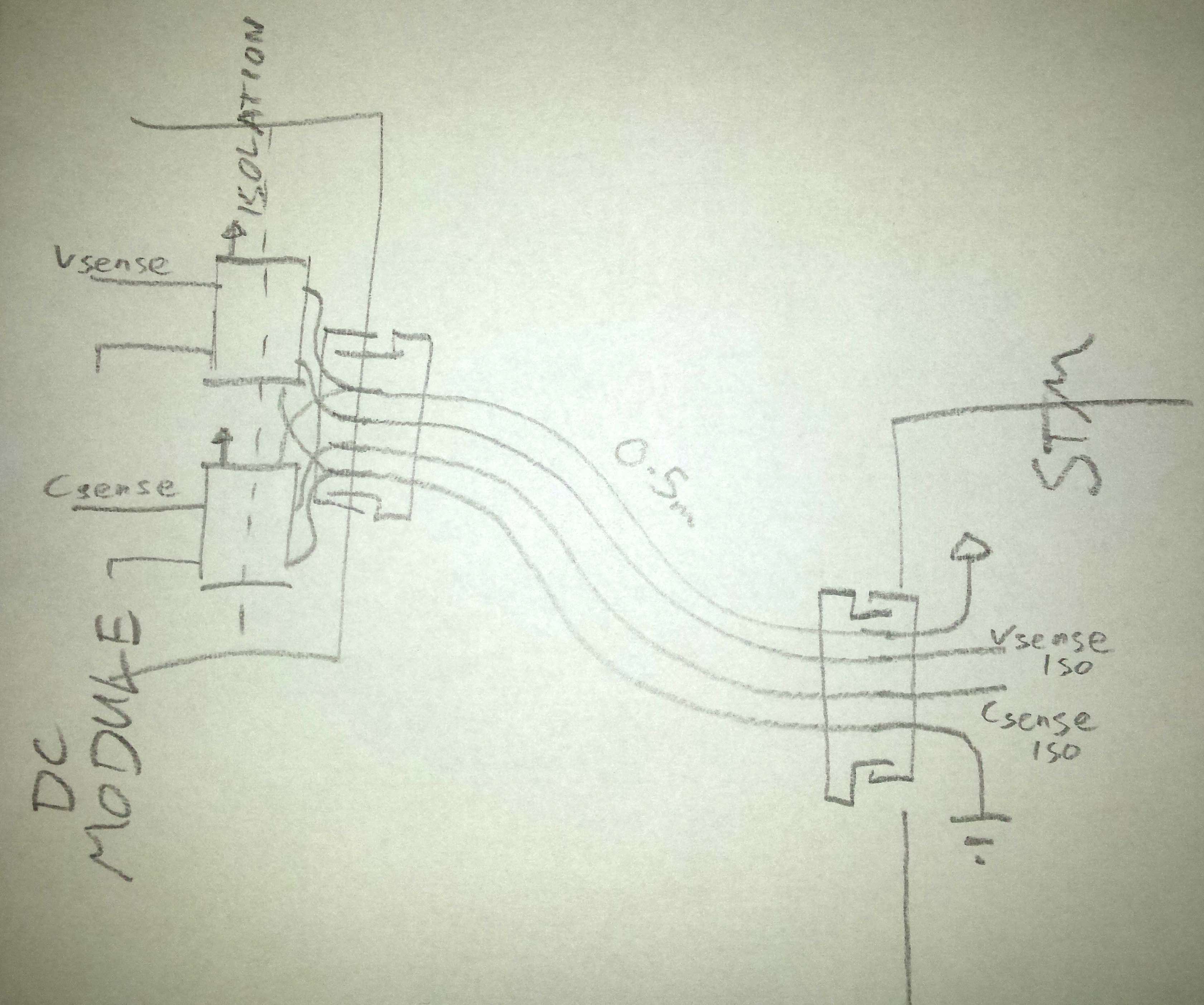
Then in trying to get a better picture in my head of how this could work, I sketched up the following ideas. From left to right you have a baseboard with the STM32 core (likely 144pin STM32F303ZE), the baseboard has a good number of CT’s (perhaps 6), ACAC input, temperature and pulsecounting. The baseboard could then be extended with shield-like boards that access further IO on the baseboards STM32 core. The second board from the left shows a shield with 12 CT’s and 2ACAC inputs. The same result could perhaps be achieved with two smaller 6 channel CT boards and two connector rows (right top & bottom):

More to follow…

1 Like

Are you intending that the CT connectors and AC connectors be the same as the emonTx?

We are hoping for a modular front end, so yes and no. There will definitely be front ends that use the usual connections, but alongside that there may be others, like perhaps a front end with all screw terminals so that direct connections can be made to CT’s and VT’s.

And since the front end boards will possibly be smaller numbers of channels you could mix and match so you have enough holes of differing types to hook up a multitude of VT’s and CT’s and other things.

It’s not only the actual connectors that might vary, but the burdens might differ, there maybe amplifiers to provide various levels of gain. etc etc.

But yes, I suspect there will possibly be a product combo to directly match/replace both the emonTx and emonPi in time.

I like the general idea of being a modular system with additional boards stacked on top. However, I don’t like the idea of connectors being present on both the front and back panels. Although this looks good in drawings I think it makes for a tricky installation since a gap needs to be left on both sides when it is mounted to the wall. I would prefer to see connectors on one side only, the other face used for status LEDs etc. Many other electronics in similar form factor (network switches, routers) only use the back for connectors and I think it can make for much nicer installation since it allows for much neater cable management.

Another option to possibly add to the list for expansion boards is DC monitoring. This could allow for monitoring of the solar panel DC side of solar installations or batteries. May not be that useful and likely to be a bit of a regulatory nightmare since it would be bridging the AC-DC isolation of the inverter.

1 Like

This is one of those FWIW type of things, but some routers and switches use the front panels for connectors too. :wink:

I maintain two radar systems that use them exclusively. Big name manufacturers, like Cisco and Nortel.

KR12120

Not saying that front panel connectors placement is better, just that it’s not all that uncommon.

Yes, rack mount has connectors on the front, but minimal on the back other than power. In general I think power monitoring equipment like this will be mounted flat against a wall or enclosure where flat wall space is often limited.

A rail mount enclosure could be worth considering, although perhaps of limited use of the regulations say it shouldn’t be mounted in the main breaker box.

Yes good idea, @danbates is working on a DC monitoring board, many of the developments could applied to a STM shield design.

1 Like

I wouldn’t go to the effort of designing a shield for dc monitoring.
Except for low voltage battery management perhaps.
But anything beyond that no. For isolation reasons, let alone regulation.
I recommend incorporating ribbon cable adaptors for analog voltage input OR spi bus for communicating with an adc on the external modules. The isolation could then be handled at the interface at the external module.
I’ll post an example of what I mean later today.

1 Like

I understand your points, I myself do not like the idea if connectors all the way around the device (on all 4 edges) but I do understand why some might favour that design when trying to keep a device small as possible (smaller case, cheaper pcb) whilst offering the biggest number of connections possible for a compact (single pcb) design.

Although I would also like a design that attaches to the wall and all connections are on the one lower face so that the cables all hang down, I do not think this is entirely viable as it demands a lot of PCBs to have that much “lower edge” so personally I’m (currently) in favor of the current emonTx style and keeping all the CT’s and VT’s connected on the lower face and keep the comms and digital connections on the top face, this does however allow dust etc to accumulate in those top connectors so perhaps rotating it through 90° to use the “sides” might be better, but I would still like to see the ADC inputs one side and DIO the other.

Looking at @TrystanLea’s final drawing, I think that sort of design, but with the ADC inputs double stacked on on edge and additional pulse counters or temp sensors or mbus inputs or so inputs etc.

I would prefer to see the device’s analog and digital aspects clearly separated.

1 Like

I’ve had a chance to read the thread and seems there’s alot of interest in going modular.
I agree it’s the way to go.

In terms of DC monitoring, in my last post, by ‘external module’ I meant an enclosed module far enough away from the STM board to be a distinct piece of equipment.

I’d have isolation handled at the external module, and output signal(s) using JST PHR compatible ribbon cables. What do people think of these?
There could be 6 pin varieties for SPI. 4 pin for I2C. 4 pin for 2-channel voltage outputs (for example for sensing current and voltage of a DC system).
I’ve put together hundreds of boards using these connectors and they feel good to use, clicking on insertion, and have a fairly high pull-out resistance.
They’re also used here - as an example of an existing system.
The SPI or I2C connections could interface with an ADC directly or the MCU of course.

I’m just talking about a DC module, but other modules that’d best be isolated could make use of the same connectors? Just a thought.

I’ll be going through a revision of the DC module, so could look at voltage outputs, I2C, or SPI.

Click lock connectors that allow for waterproofing a round cable could be an advantage, although there’s been no real effort for waterproofing household emon gear and I don’t see a reason to start now.

It’s almost this simple, excluding a separate stage of buffer amplification as per datasheets, but that’s a seperate matter from STM32 dev:

Voltage output using unity gain opto-iso buffers acpl unity gain iso amplifier.pdf (144.4 KB)

1 Like

Hmmm.

You forgot pin 1 of the ACPL-C8** “Supply voltage for input side (4.5 V to 5.5 V), relative to GND1”

which implies a separate, 5 V power supply isolated to at least 1500 V.

For clarity, I can suggest either a 6-pin jst connector for isolated serial comms, or a 4-pin for isolated voltage inputs, or both. Serial comms being my preference.
PCB thru hole 2mm pitch mounts can be left for the later addition of jst connectors, by User discretion.
The case can have knockouts to make the connectors available.
I’m open to other connectors being used.
Also, I have an eagle lib for jst-phr type conns if needed.
If it’s easier, I can make a simple connector shield at a later date.

@Robert.Wall I’ll be going through CE testing, as any DC system module should, we’re working out the isolation details.

My understanding is, if you are offering a unit for sale in the E.U., then if it falls within the scope of the regulations, it must be ‘CE’ marked.
The nearer you can get to CE compliance before submitting it for test, the cheaper the testing process will be.

A short update for those interest first in DC monitoring. Glyn and I had a pre-testing meeting with CASS the company who we use for CE testing about emonDC development which was positive. @danbates is continuing to work on the next revision of emonDC although not STM based at this point.

Back to the STM32 hardware topic, I found a source of eagle libraries for a variety of STM32 packages, which look useful:

https://www.diymodules.org/eagle-search?desc=1&text=stm32

https://www.diymodules.org/download/eagle-libs/usr/1012210646/conv/micro-stm.lbr

STM32F303 100pin package:

There’s no 144pin F303 in the library unfortunately but there is for the F101 not sure how easy it would be to modify.

Easy I find, but a couple hours work perhaps making sure everything matches according to the datasheet.

Just to note, that for a new hardware project, it’ll be worth looking at KiCad, which I’ve heard has improved a lot recently, it’s open-source and doesn’t have board size restrictions.

1 Like

I’ve finally had a little time to look at STM32 hardware again :slight_smile:

First a good friend of ours and original NanodeRF designer who helped get OpenEnergyMonitor internet connected energy monitoring started: Ken Boak (https://twitter.com/Monsonite) has kindly shared a number of STM32 eagle files with us, perhaps the most useful design at this stage while learning about the STM32 platform is his ARMiGo design.

The ARMiGo is a 48-pin STM32F303 mini development board that includes basic power supply, ST-Link and USB connectivity. Ken blogged about the design in early 2014 here: A mini-ARM board, the ARMiGo | Wicked Device Shop

The Eagle schematic and board files can be downloaded here: ARMigo2_3.zip (132.8 KB)

Using this design and cross-referencing with the schematic for the nucleo f303 downloadable here:
http://www.st.com/en/evaluation-tools/nucleo-f303re.html and the pin-out reference accessible from within the STM32CubeMX application, Im slowly getting a clearer idea of what is required to put together a basic design.

I also realise that the easiest way to get the eagle components for the STM32 range is to use the STM provided bxl CAD fiiles and the recommended route of using the https://app.ultralibrarian.com online tool that can export these bxl files into a variety of formats used by common electronic design tools such as Eagle or KiKad.

stm32f303rxt (64-pin) stm32f303.lbr.zip (5.1 KB)

The CAD files downloadable from STM also include files for f303 100pin and 144pin designs. The xls file Select_BXLfile.xls details which bxl file to use.

My next step will be to read through the AN2586 and AN4206 application notes on getting started with STM32 hardware design.

1 Like

4 posts were split to a new topic: STM32 Calibration

ST-LINK JTAG/SWD Firmware Upload

The nucleo development boards come with an integrated ST-Link-v2 programming board that you can snap off.

The ST-LINK/V2 is an in-circuit debugger and programmer for the STM8 and STM32 microcontroller families. The single wire interface module (SWIM) and JTAG/serial wire debugging (SWD) interfaces are used to communicate with any STM8 or STM32 microcontroller located on an application board.

ST-LINK-V2: ST-LINK/V2 - ST-LINK/V2 in-circuit debugger/programmer for STM8 and STM32 - STMicroelectronics

M-07723

Alternatively you can buy cheap ST-Link-v2 programmers on ebay that avoid the need to add the full st-link programmer hardware to a STM32 hardware design. Ken’s ARMiGO design above has a 5-pin connector for programming with an external ST-LINK programmer.

In order to further my understanding of the hardware part of st-link firmware upload, I snapped off the st-link adapter on my nucleo development board and then following the pin out as documented on the schematic for the nucleo rewired both parts together:

Download the nucleo f303re schematic here:
http://www.st.com/resource/en/schematic_pack/nucleo_64pins_sch.zip

The 6-pin SWD connector can be seen on the left of the ST-link adapter board.

SWD

Pins

  1. n/a
  2. T_JTCK: Clock signal of target CPU, connects to PA14 on STM32
  3. GND, connects to GND
  4. T_JTMS: → SWD data input/output, PA13 on the STM32
  5. T_NRST: Reset → NRST on the STM32
  6. T_SWO: Single Wire Output → PB3 (Optional, not needed for firmware upload, used for output)

Then on the nucleo development board part, the schematic indicates the position of PA14, PA13, NRST, 3V3 & GND:

morpho_cn7

3V3 power for the nucleo STM32 board can be accessed from JP1 on the ST-link programmer.

Picture of the connected boards:

and firmware upload worked just the same as pre snapping off the ST-link board :slight_smile: