So you inspired me to look into how this serial programming stuff works, it all seemed just a bit too flexible to be true. As I mentioned before I’ve only ever used the SWD interface for flashing, so I’ve not tried any of this and it’s based solely on some quick research this morning.
I came across AN2606. Section 6 seems to be the relevant one for your device. The good news is it does indeed poll multiple UARTs for an incoming 0x7f and then uses that UART. The bad news is, it requires the UARTs to be mapped to known pins (PA9 and PA10 for UART1 and PA14 and PA15 for UART2).
In your experiment here, you used PA9 and PA10 (UART1). Are you sure when you tried UART2 you used PB3 and PB4, and not PA14 and PA15?
The schematic has the FTDI programmer header connected to PB3 and PB4. Once your f/w is up and running it can easily map those pins to UART2, but until then I think the bootloader will have UART2 mappped to PA14 and PA15 (at least according to AN2606).
I think this is the critical point I missed, and I agree it’s a great goal to be able to program it with your existing USB<->UART programmer.
I think you should be ok there. For both the ST-LINK programmers and the serial programmer the 3.3V pin is an output from the target and an input to the programmer (it’s not used to power the target).
In the case of the ST-LINK programmer, it’s pin 1 on CN4 in your schematic excerpt here. Although as you point out, on the ST-LINK strip programmer that pin is disabled (hence your n/a). On more advanced ST-LINK programmers, the programmer senses the voltage at that pin to know the target’s Vcc. I guess for the Nucleo strip programmer they can safely assume everything is running at 3.3V and it clearly works fine without it.
Checking the schematic of your shop-sold serial programmer here it looks like that 3.3V pin is how the programmer gets powered, i.e. the target board is powering the Vcc of the SILabs CP2101 via that pin.
Thanks for spotting and looking into it @dBC. I did not test PB3 and PB4 unfortunately but really appreciate you looking into it. I will test with the f303re I have here tomorrow. Il have to get some mini wire links on those small stm pins on the prototype to test or send for another.
No problem. I’ll be interested to hear what you find, but it seems impossible for the UART to be plumbed to two sets of pins at once so I suspect PB3/PB4 won’t work, unless there’s a typo in AN2606.
The other thing I noticed in AN2606 is that the bootloader only polls two UARTs (UART1 and UART2), so if you ever do go the three UART approach I suggested above, be sure to use UART3 for something that you don’t plan booting over (OneWire or ST-LINK debug printfs).
[EDIT] - and the bootloader is burnt in at the factory and is un-erasable. So once you get the pin issue sorted, I think you should be able to use either method (ST-LINK Vs Serial) to program your virgin chips as they arrive from Farnell etc.
I’m happy to say everything worked with the first prototype PCB!
With special thanks to @danbates designer of emonDC for helping to assemble the board with his SMT soldering skills and @dBC for finding the issues fixed above that meant all of this worked.
So far we have tested:
Power supply
ST-LINK firmware upload
Serial firmware upload
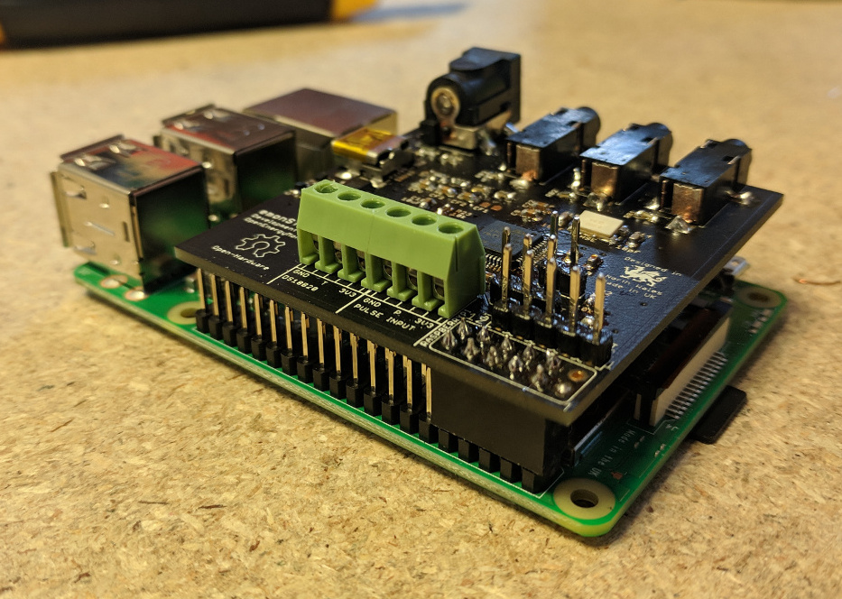
RaspberryPi automated serial upload procedure
LED indicator
8MHZ HSE oscillator
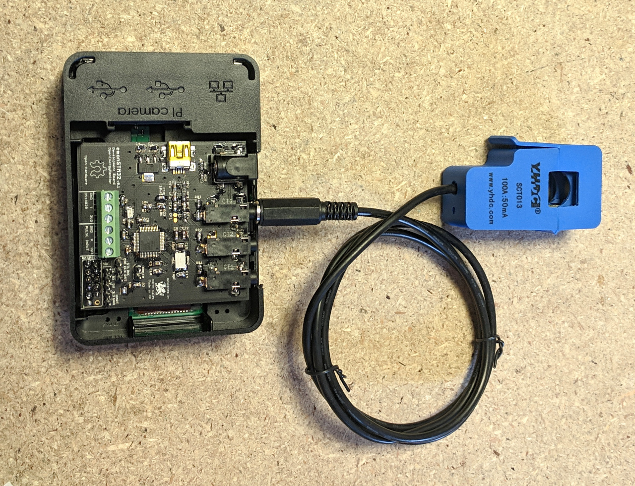
CT and ACAC power measurement
DS18B20 temperature sensing input
Pulse counting input
Datalogging to emoncms via raspberrypi serial and emonhub
All working well.
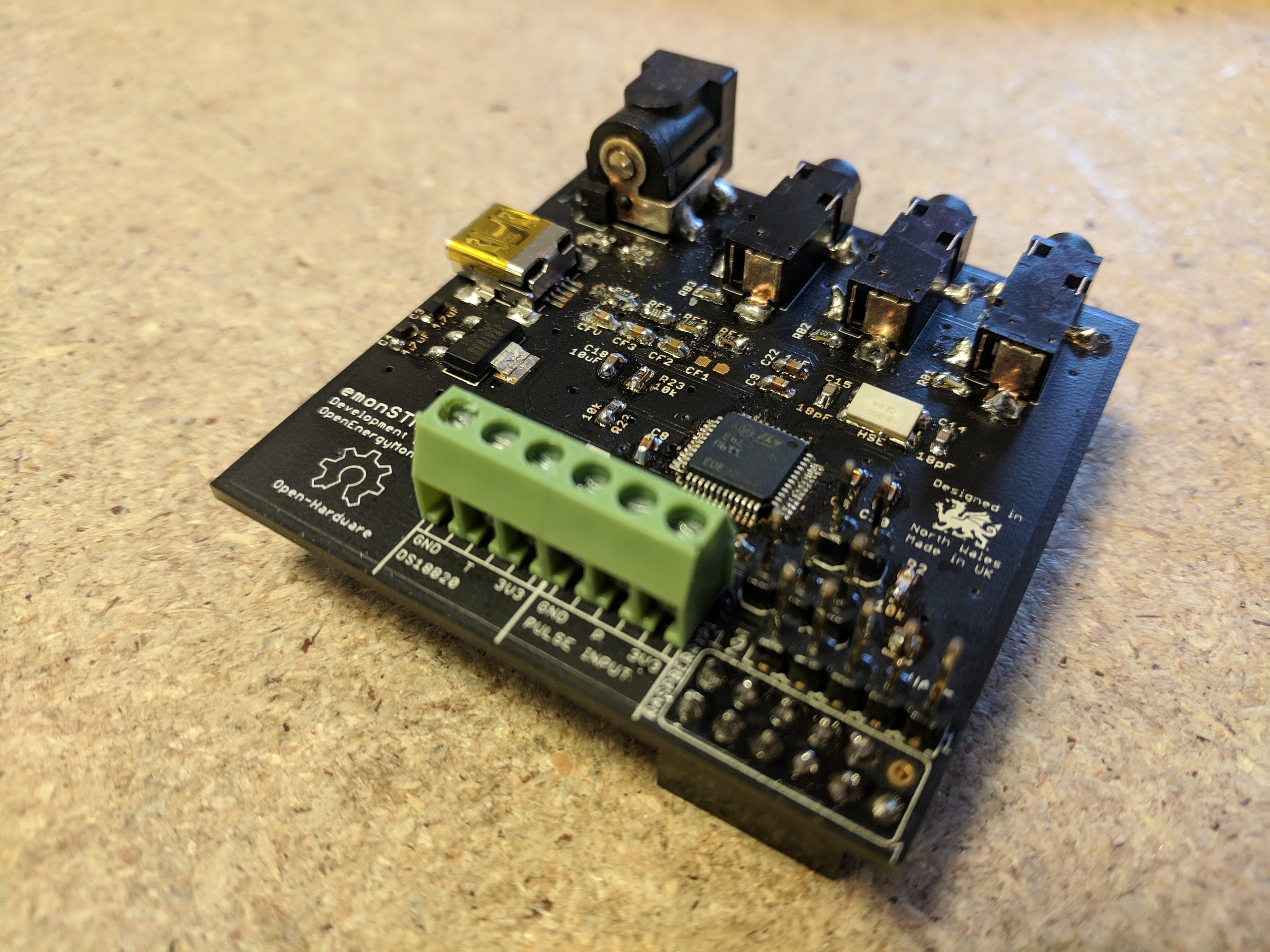
Here are a couple of pictures of the board, http://ragworm.eu/ where very kind to update the order with the fixed design and then fit it on one of their black soldermask board runs which looks particularly nice:
The next step is to test the filter design in more detail and run the unit in parallel with an EmonTx. @danbates is looking into firmware libraries for RFM69 support and we will be revisiting the requirements of a fully featured board as discussed here STM32 Hardware Development.
Overall very happy with how this first prototype turned out
This is compatible with LowPowerLab radio packets. I’ve looked at JeeLib packets and think I have a good understanding of the main differences, yet can’t quite get it working. So there’s something I’m missing there. For the ‘jeecompat’ project, I have a github branch here.
Just a heads up to anyone who might have cloned my 1-wire uart off-load example above (@TrystanLea@danbates): you get better results if you enable “Single Sample” on the uart(s) involved:
It has five times lower ppm/deg C drift (20ppm vs 100ppm), with 0.1% accuracy, so should improve accuracy, at least related to the reference error. I guess if calibration is performed the 3% inherent accuracy of the STM32 internal reference will be overcome, but not everyone has access to an accurate multi-meter. Having an accurate external reference on the VDDA means the internal reference would not be needed to be used in any calculation of the supply voltage, and hence full scale value.
I’ve bought an STM32F303 Nucleo board and intend to get an energy monitor working using it. My background is RF engineering, I am not a programmer, although I do dabble, so I wont be able to help much with the software. I’d be happy to help with the hardware design if I can be of help with the project.
I’ve been sifting through the stm32 manuals and followed most of the design recommendations. This has ended up with my choosing a voltage reference, it’s 0.1% and 50ppm.
On the case. Our large board has the footprint for an ESP12. When we go farther with the smaller basic board, we can look at getting a footprint or module header there also.
I think, overall, the rational for using rPi is clear, but we don’t want to ‘wed’, as you put it, the design to it either.
Contemplating the recurring question of NULL values in the emonCMS graphs, many of which appear to come down to an absence of synchronism between the data source (the emonTx usually) and emonCMS, I wondered how practical/desirable it would be to include a radio code clock in the STM32 sensor node - not necessarily for the purpose of providing an absolute time, but to provide a timebase for reporting that would be locked to World time - hence Internet time - that would not suffer from the drift that causes the database to have either null values or to receive values that get overwritten by the next one to arrive.
Or could it be an issue with the emonhub - MQTT - emoncms interface? Even on the EmonPi there are 2 additional steps between the Serial output from an EmonTX and the Input of EmonCMS.
You could eliminate that with a direct link, via WiFi from the EmonTX to Emoncms via an API call and possibly timestamp that data at source. I’m still not clear why the default from emonhub was changed from the API to MQTT.
@Robert.Wall thanks for reminding of this. A related topic came up while discussing the new stm32config module. Whether to poll the stm32 for the data from a directly connected rPi or wait for the interval data (which could drift in time). Same issue could crop up with the Nulls in emonCMS. Apart from hacking emonCMS there are better solutions…
My feeling is firstly, to specify an accurate 32kHz crystal for stm32’s rtc.
And then to have a method which involves correction of the node/stm32. The hub/rPi would have to detect a delay or advance of the interval, then send a command. The node/stm32 would have to interpret this command and correct it’s time.
Cheaper than building an atomic clock ourselves.
I guess time-correction is how everything along-the-chain works, going as far back into the internet as I can imagine, there’s prpbably a computer somewhere reading an atomic clock, and ‘internet-time’ is periodically being adjusted to it… I’m guessing.
Does that speed assume the MQTT broker is on the same machine? If so that is an assumption (I run a separate broker).
The other issue is that MQTT does not buffer like the API call does. If for some reason emonhub does not make the connection, with MQTT the data is lost, with the API interfacer it buffers until the data can be sent.
Comes back to tying this to an RPi and emonhub I feel.