STM32 Development

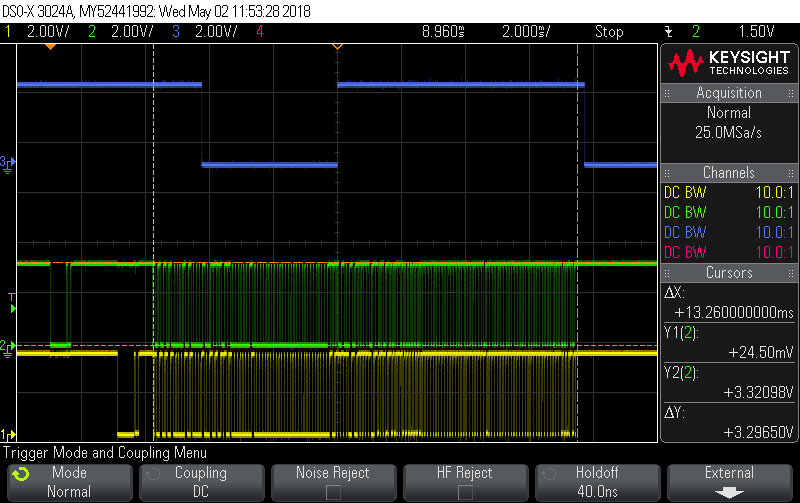
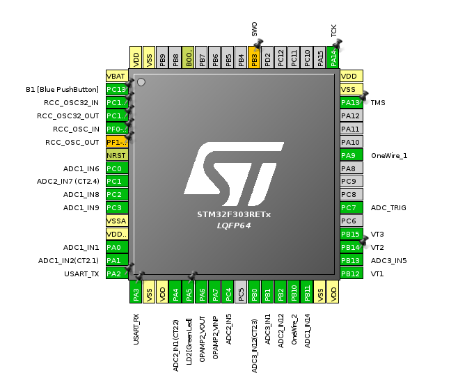
OK, I added a second OneWire bus as further proof of concept. In the following trace, Green and Yellow are the two OneWire buses, and Blue is still the ADC/DMA ISR. Each bus has just one DS18B20 on it and you can see both buses happily chug along sucking in the 9 byte scratchpad even as the CPU heads off to work on the V,I maths. The pinout for the two OneWire buses is as posted a few posts back (CPU pin diagram).

The output now looks like:

emonTxshield Demo 1.11
Patch PA0 through to PB14 for V!!!
1Wire DMA buffs: 384 bytes
ADC DMA buffs: 11200 bytes
CPU temp: 35C, Vdda: 3304mV
bus0 status: 0xe0, crc:  ok, temp: 23.188
bus1 status: 0xe0, crc:  ok, temp: 23.062
 3: Vrms: 1309.87, Irms: 1309.53, Papp: 1715312.94, Preal: 1715312.00, PF: 1.000, Count:84013
 4: Vrms: 1309.87, Irms: 1309.29, Papp: 1714994.33, Preal: 1714994.00, PF: 1.000, Count:84013
 5: Vrms: 1309.87, Irms: 1309.15, Papp: 1714821.24, Preal: 1714820.00, PF: 1.000, Count:84013
12: Vrms: 1309.92, Irms: 1309.28, Papp: 1715058.29, Preal: 1715057.00, PF: 1.000, Count:84015

Note carefully the comment in the code about the DS18B20 code:

//
// Reset both 1wire buses to start a command. This code is NOT an example
// of how to use the DS18B20, in fact, it’s an example of how NOT to use it.
// It simply uses two DS18B20s (one per bus) as a handy OneWire slave in order
// to demo/test UART off-load of OneWire transactions. As such it does no device
// discovery, and no device selection by ROM code. It will only work provided there
// is only one DS18B20 per bus. There are plenty of examples on the net implementing
// the full DS18B20 discovery and addressing stuff, use them instead if you’re
// trying to do anything serious with DS18B20s. Here they’re just a handy OneWire
// slave to bang against in a very primitive fashion.
//
txshield_demo_11.tar.gz (922.9 KB)

In all demos prior to this one (demo 12) I’d left all interrupts at the same priority (meaning no interrupt interrupted any other) but with the ADC/DMA power-maths ISR running for about 4 msecs out of every 12, and the systick trying to tick every 1 msec, we were losing time big time. demo12 makes the ADC/DMA interrupt lower priority than all others, and enables nested interrupts.

It also splits out the ds18b20 code into its own module, and now really hammers on the OneWire buses for added stress testing:

txshield_demo_12.tar.gz (936.6 KB)

Thanks for sharing this dBC, sorry I haven’t had much time for this recently, I haven’t found the time to lay eyes, let alone hands on the stm32. I did manage to quickly upload demo 11 to the repo (and I intended to post but time ran away from me). I will (tommorrow?) upload demo 12 so that at least keeps up to date.

Is there any real advantage to using multiple 1-wire buses (other than if a ridiculous number of sensors is required)? I could see that advantage of having one sensor to a bus with an emonTx etc as the sensor id recognition/management was a bit awkward, but would I expect there will be no such issues with the stm32 if it gets implemented properly.

No problem, I figured you’d get to it eventually.

Hard to say definitively, and I’m certainly not pushing you towards supporting multiple buses, just demonstrating that once you go the UART-offload route, anything is possible (well, two buses is possible… “anything” might be stretching it ;-).

1-wire relies on pull-ups to bring the signal back to a ‘1’ within the required bit time so depending on bus loading, cable lengths, and capacitances etc. it can all get a bit marginal. There may be 1-wire topologies where having two buses could help with all that, but ultimately I think it’s a decision for the system designer as to whether it’s worth the cost. In a stm32 based product, I think the cost would just be the extra connector space, although even there you might be able to do something clever with a connector to support multiple buses.

Yes, I’ve taken advantage of that in the demo code. I’ve not ported any of the discovery code to the demo so it only works with one device per bus. In a real product I think people would absolutely expect to be able to hang multiple devices off the one bus (regardless of how many buses end up being supported).

There are plenty of ds18b20 libs out there for the stm32, but all the ones I found all use the cpu to do the precision bit timing, which involves busy cpu spins with interrupts off. Recently, while doing some stm32 uart coding on an unrelated project, I happened across their SingleWireHalfDuplex with OpenDrain pin mode and remembered Maxim’s Tutorial 214 so decided to code it up and see how it works. I think it’s a far superior approach to cpu bit-banging, so hopefully there’s enough of a skeleton here in the demo code to encourage that approach as the path forward for 1-wire (regardless of how many buses you decide to support).

1 Like

Hopefully the connectors will be interchangeable like the VT/CT front ends, I really dislike the rj45 connections, on my own hardware I tend to use tool-less terminal blocks (I say tool-less but I use a screwdriver to push the levers, perhaps screwless is a better term) they are easy to use, they apply a constant sprung pressure on the bare wires rather than over or under tightening a screw, plus the lever can be on the same face as the entry which makes them ideal for applications like the emonTx.

But I know the demands and desires of everyone cannot be accommodated in one design so as much as I would ideally like to avoid multiple connections along one track, I think interchangeable front (and rear?) ends is the way to go if we can find a suitable board to board connector. It would make the main board more desirable if there are multiple front ends for it and more flexible and cost effective for (commercial) users to be able to manufacture their own bespoke front ends rather than build a complete monitor or suffer the comprimises of a product made for the masses. It’s a model that has worked for Arduino shields and Raspberry Pi hats, should work for us too. So the number and type of one wire buses/connections could be left open.

I agree regardless of how many buses/conns there are we should opt for the most efficient lib so your info is of great value, I cannot comment on the tech aspects of what you found as I do not know the libs or the code well enough to recognize the benefits, but I like what you’re saying :slight_smile:

1 Like

Turns out I’ve been slacking more than I realised, I had done v10 but not v11 OR v12, I have now done both so we are up to date.

The changes from 10 to 11 can be seen here (Comparing 0.0.10...0.0.11 · stm32oem/stm32tests · GitHub) and the changes from 11 to 12 here (Comparing 0.0.11...0.0.12 · stm32oem/stm32tests · GitHub).

@TrystanLea I realize that you’ve had your hands full recently managing the progression to emoncms.org billing & exporting of cloud data tools, but wondered where STM32 development fits into your future plans.
I’m conscious that STM32 development has slowed somewhat, and with no clear pathway or direction, there’s a fear that contributors may jump ship, and put their time into something else where there is some momentum.
I realize that it would be difficult, but are you able to lay down a development schedule, or even let us know when this work will have your full attention.

Hello @Paul, I’m keen to get back to it once I have the sync tools complete and we’ve setup the ability to access OEM shop emoncms credit in emoncms.org.

1 Like

Hi

I have been following this thread closely. I understand most of it in principle but not the programming in detail.
I Have an F303 and an EmonTxShield with 4 ct’s and a shop 9V AC Voltage source.

I have the latest version software from @dBC via the updates in the repo provided by @pb66.

Every thing is working and after a setting up voltage calibration I am getting sensible results.

How easy would it be to add an ESP serial connection to the F303 so that the results could be sent to a local emoncms using an ESP8266 WiFi Adapter for EmonTx to test real world monitoring?

Looking at the EmonTx code it does not look as if it would be a major job to match the formatting needed by the ESP.

I have switched 3 of my EmonTx over to using the ESP. I am getting much more reliable results than I was with RFM.

Version 13 enables an opamp and includes its output in the ADC scan, so you can read its value. I also finally updated my STM32CubeMX and HAL which caused a few additional diffs.

txshield_demo_13.tar.gz (1.1 MB)

Any news Trystan?

Hello @Bramco yes, I have finally had some time to spend on this again and have made good progress over the last couple of weeks. I have been writing up a mixture of a guide on getting started with the STM32 and development notes up here as I learn:

https://github.com/TrystanLea/STM32Dev

also copied here:
https://github.com/openenergymonitor/STM32

I’ve had some help from @dBC and @Robert.Wall on PM understanding the ADC’s and a better method for DC offset removal, which is much appreciated! I got caught out for a bit using the digital high pass filter that we use in EmonLib but at the higher STM32 frequency resulting in lower than expected Vrms readings, @Robert.Wall’s DC offset removal approach sorted that nicely in a way that is independent of sampling frequency.

This approach is included in firmware examples Emon1CT & Emon3CT.

I’ve tested the in-built opamps to be used as voltage followers for the bias and a basic anti-alias filter (calcs still todo), notes up here: https://github.com/openenergymonitor/STM32/blob/master/docs/prototype1.md

I would like to go through each of the hardware features that we would like to add to the main design to make sure I understand what can or cannot all run at the same time - preserving a core goal of full continuous sampling across a large number of CT channels, thanks @dBC for your DS18B20 example above. Plus there are plenty of basics like serial comms on the ST-link, and USB DFU that I need to understand and test.

I’ve also sketched together a basic eagle design combining a number of features I would like to see, more so that I can see how things might fit together and potential board layouts, routing requirements rather than setting the design in stone at this stage: https://github.com/openenergymonitor/STM32/tree/master/Hardware/3

Still going through the steep learning curve :slight_smile:

1 Like

Full list of content in the development repository so far:

Getting started: STM32 (Arduino integration)

Introduction to STM32CubeMX

Notes on hardware development and initial designs:

Firmware Examples

Other:

1 Like

Great to hear things haven’t stalled! :slight_smile:

I’ll start trying to follow again.

Simon

Great :slight_smile: if you try going through any of the above examples and have any suggestions & additions that would be useful for the guides let me know.

Hi

Working through examples.

Using PlatformIO

In ~/STM32/Emon3CT $

Got the following warning :

Warning! monitor_baud option is deprecated and will be removed in the next release! Please use monitor_speed instead.

Then these errors:

Src/main.c:210:8: error: ‘for’ loop initial declarations are only allowed in C99 mode

Regards

Ian

Hello @ian, I have corrected the platform.ini files to include the c99 flag, thanks for spotting! I was using the Makefile.

I am however having trouble getting the examples to print numbers using platformio, works fine using make… I note you reported the same error here but cant see the solution!?

The -Wl,-u_printf_float flag is in the platformio.ini file https://github.com/openenergymonitor/STM32/blob/master/Emon1CT/platformio.ini#L13

Hi Trystan

Still get one error:

Src/main.c:108:3: error: ‘for’ loop initial declarations are only allowed in C99 mode

If I use the platformio.ini file from @pb66 STM files it compiles OK

platformio.zip (556 Bytes)

But it does not upload with PIO!

I have switched to make for further testing and that does work in so far as I can compile and upload but at the moment I cannot get the terminal to open.

Edit
All working fine. Upload and Terminal issue was USB plug displaced!

Thanks Ian, I will do a bit more testing with platformio. Glad to hear the makefile worked ok.

For those interested here is a rough outline of my STM32 development plan

STM32

Goals of the project:

  • Higher resolution 12 bit ADCs
  • Higher sampling rate
  • Continuous sampling on all Voltage and Current channels
  • Shield/extension design
  • RaspberryPi core, local datastorage, visualisation
  • Learning resources on the STM32 platform to enable modification & customisation.

Steps:

  1. Work through STM32 power supply, clock, programming sub circuits, check understanding, component sourcing. Put together base board design (equivalent of a STM blue pill, or Ken’s ARMIGO) potentially with a couple of CT and ACAC sensor inputs for initial testing.

  2. Filter design for CT and ACAC voltage input circuits.

  3. Construct 3D model of enclosure options, visualise different stacking design options, connectors, raspberrypi location. Ease of manufacture & assembly.

  4. Verify MBUS reader running on STM32 alongside energy monitoring code.

  5. Understand @dBC one wire code and timing implications.

  6. Review base-board feature requirements:

    • STM32 core and pin count
    • Number of CT sensor inputs
    • CT sensor mapping to ADC channels
      sequential vs parallel sampling capabilities.
    • Number of ACAC Voltage inputs
    • DS18B20, pulse counting connector types and numbers.
    • MBUS
    • RaspberryPi connector and mounting
    • ESP8266 on board
    • RFM69 support
    • RTC
    • Display & push button

Evaluate cost implications of including on board vs requiring shield additions for items such as MBUS, RFM69 & ESP8266.

  1. Create PCB layout for first hardware design. Get prototypes, testing, fix issues, EMC prelim, design iteration and revaluation of next steps from this point.

I will keep updating as this progresses. This is work I’m doing alongside emoncms and emoncms.org development and so development will be a little discontinuous at times.