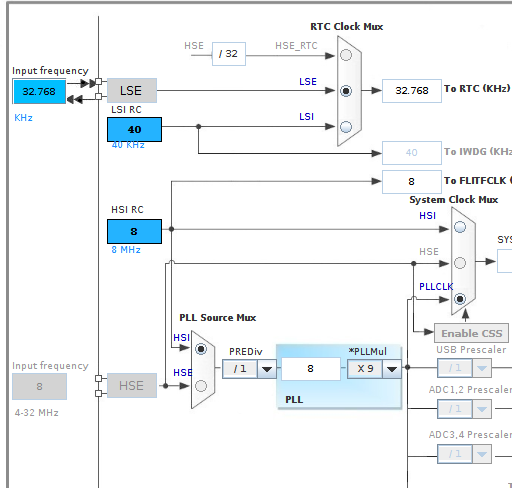
So far we have used the HSI (high speed internal clock) as the clock source. I’ve been reading up on the LSE clock (32.768kHz) for accurate RTC timing and note the presence of this clock on the Nucleo development board. I also note that there is an option to have an external high speed clock (8Mhz) which could be used for both the RTC and the system clock. Do you have a view @dBC as to the best way to go?
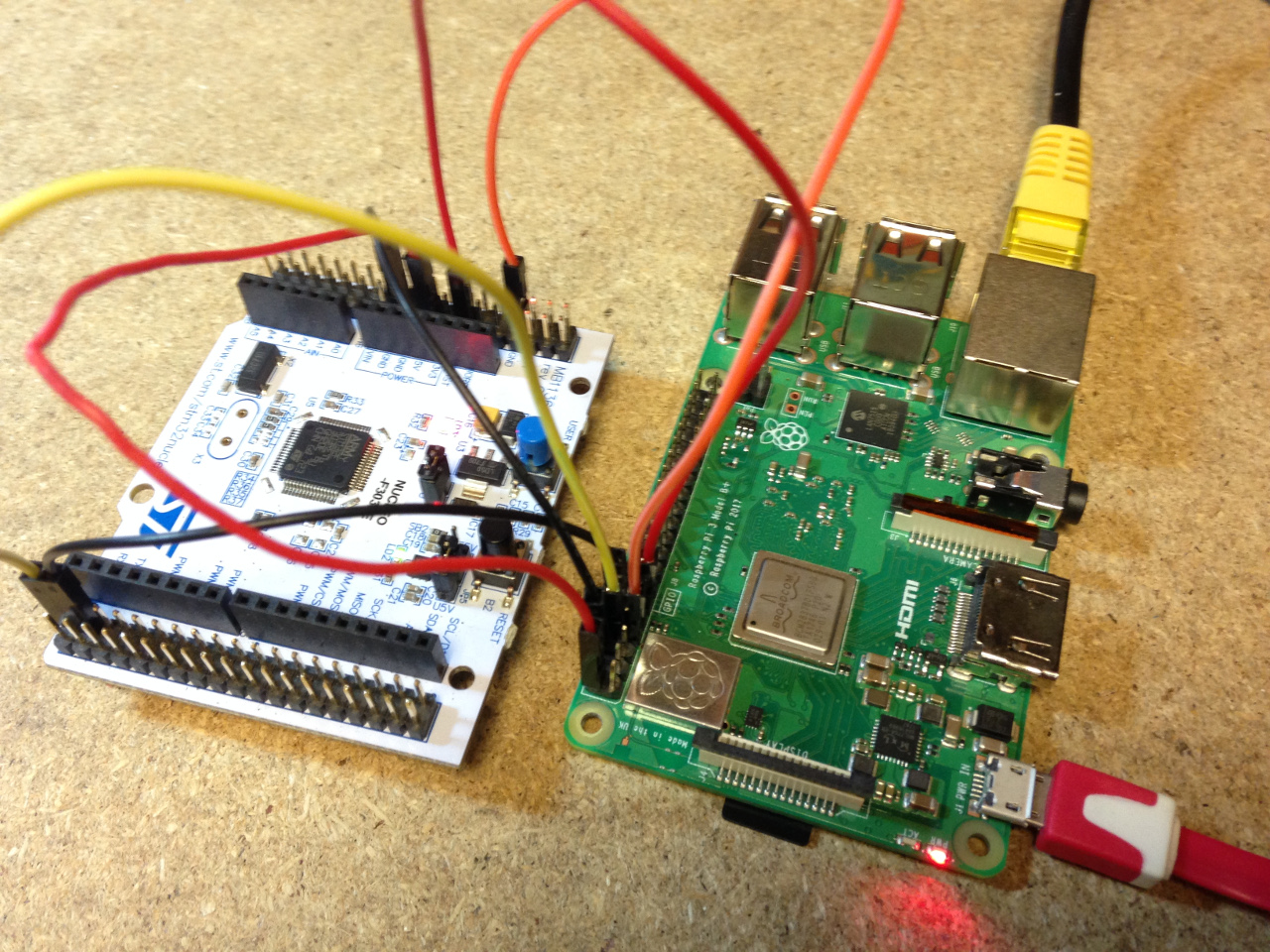
Another small step, I’ve tested and written up an example of how to upload firmware to the STM32 from a raspberrypi including automatic setting of BOOT0 and automatic reset so that the upload could be called as part of an OTA update process. Two GPIO outputs are required rather than the one used for autoreset with the AVR but its relatively straightforward.
Not really. The clocking is very flexible so go for whatever fits in best with the rest of the design. For me that’s usually been a HSE crystal because they’re readily available. Do you plan using the RTC for anything? I almost used it once on a battery operated project that needed to wake up to count/time pulses but otherwise, if the stm32 is never going to sleep then I’ve found systick to be sufficient for maintaining msecs-since-booted time and never needed actual date and time. If yours will be always-running and closely coupled to an RPi, it might be easier to let the RPi worry about date and time.
Thanks @dBC, is there a reason that you went for a HSE crystal 8Mhz? vs the internal HSI? I imagine the timing is better, but is it significant? For energy monitoring we need to accurately calculate increments in watt hours and so the accuracy of timing is a factor of course.
Not sure about using the RTC, Ideally access to the RTC would be useful for an attached raspberrypi, especially if logging offline without access to internet time-servers… Perhaps its worth catering for both options on any board design, footprint for both a HSE and a LSE crystal…
I’m away from base at the moment and don’t have the datasheets handy but I’m pretty sure they list what accuracy (across temperature range) you can expect from the internal oscillator.
Yes, I’d forgotten the RPi doesn’t have an RTC, so using the stm on-chip RTC gives you that for free (well, no more than the cost of implementing some code to read/write the RTC across the serial connection).
[EDIT] - forgot to add… UART comms puts a limit on how inaccurate the clock can be. Maxim have a tutorial on that calculation here
I note however that you suggest looking for complete ds18b20 libraries that support full device discovery etc in any serious project. Do you have any recommendations?
Glad to hear it. That SingleWireHalfDuplex with OpenDrain pin mode on the uarts look custom made for implementing OneWire in the uart.
Not really. Apart from the test implementation of Maxim’s Tutorial 214 in my example code above, I’ve only ever used ds18b20s on AVR projects and just used the standard Arduino cpu based bit-banging libraries.
@Robert.Wall 's new emonLibCM V2 seems to include a full ds18b20 implementation with device discovery etc. so that’s probably as a good one as any to start with. What’s required is to merge the upper layers of that code, with the lower layers of my code above. Then there should be no limit to how many temperature sensors (or even how many OneWire buses) you support because there’s no cpu involvement with the timing critical stuff (all done by the uart).
Ooh!
I didn’t set out to do that - what I aimed at was firing off slightly lower level commands to the 1-wire and the sensors so that they could get on with doing their thing whilst the “emon” bit was doing its, and hopefully neither ended up waiting for the other for too long (and thus spoiled the timing).
Actually, most of that I think originally came from Martin Roberts.
I think Martin’s original code only reads one DS18B20. The code I use is derived from the mods to that code by DB and keeps the device data in the same order that they reply in which is based on the device id - Robert has written somewhere about this.
The issue you then have is if one ever went down, in which case the readings for the ones after the one that goes down get moved up the array. The code in the tasmota software seems to keep the readings aligned by the device id, so wouldn’t suffer from this issue - I’ve not tested that mind you and I’ve never had an issue with one of the sensors going down.
Having said all that, it would be sensible to implement any new software by making sure readings are saved according to device id just in case configurations are changed etc. This processor has plenty of bandwidth to handle that.
I’ve half-way done that in emonLibCM. You can let it find the sensors and then manually copy the locations into an array, then stop it from searching again, or you let it search always.
Wouldn’t it be better to have the system do this automatically? So keep an array of device id’s, readings and possibly status (responding/dead). At the beginning of each read cycle mark all sensors as dead, then when a reading comes in check if the id is in the table, if so save the reading and mark it as responding. And if a new one comes in append it to the table.
The manual thing never seemed to be the best way to do this to me.
That’s impossible. How can it know the difference between a failure and a deliberate change? If a sensor dies, then a week later a new one appears, was it necessarily a replacement?
Thank you for the input on the ds18b20 temperature sensing, sounds like studying @Robert.Wall’s example is good first step. I think Il come back this it at a more detailed level later on, I’m happy that I have got the basic example running which is enough to progress to the next step on hardware design.
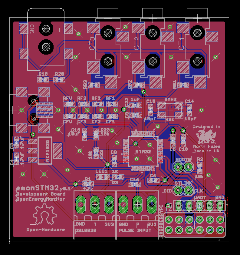
I have uploaded some of my recent development notes here STM32/stm32notes.md at master · openenergymonitor/STM32 · GitHub and a fourth design variant. It’s a work in progress, I’m trying to go through the main components of a basic design, document the design decisions and get it as clear as I can in my head how it all fits together.
Well it would be a replacement because I would have replaced it. And if I hadn’t done any additions or replacements then no response would mean that the sensor wasn’t well. I’ve never had one fail, so I don’t know how a failure happens, do they go intermittent or just drop off the face of the earth and never come back?
These systems are managed systems, not like say an open wifi access point which doesn’t know anything about what might be accessing it. We set up the systems with the sensors we need to do a specific job, in my case monitoring the Heat Bank temperatures. I have added sensors in the past but I did that, they didn’t appear out of thin air. So I knew what was going on and could then link the inputs to feeds and then to dashboards.
So IMO it would be very easy to set up and manage the connected sensors automatically.
That was exactly my point, you know that you’re replaced the old one with one that has a different serial number, therefore you assume it must, and want it to, take the same place in the list of data that’s sent to emonCMS. (Because that’s the pertinent point here.)
Precisely, managed by you. [My emphasis]
If the sketch can always assume that a sensor that has gone missing has gone forever, and the first new sensor it sees is a replacement for that, then yes, it’s easy to manage that situation. But what if you’ve added a sensor, and in the process disturbed an existing one and cause it to fail? What if two have failed and you replaced both, at the same time? You’ll end up doing quite a bit of head-scratching until you’ve found, buried somewhere in ‘Resources’, the algorithm that describes what the sketch has done.
As mentioned above, the first step on my STM32 Development plan is:
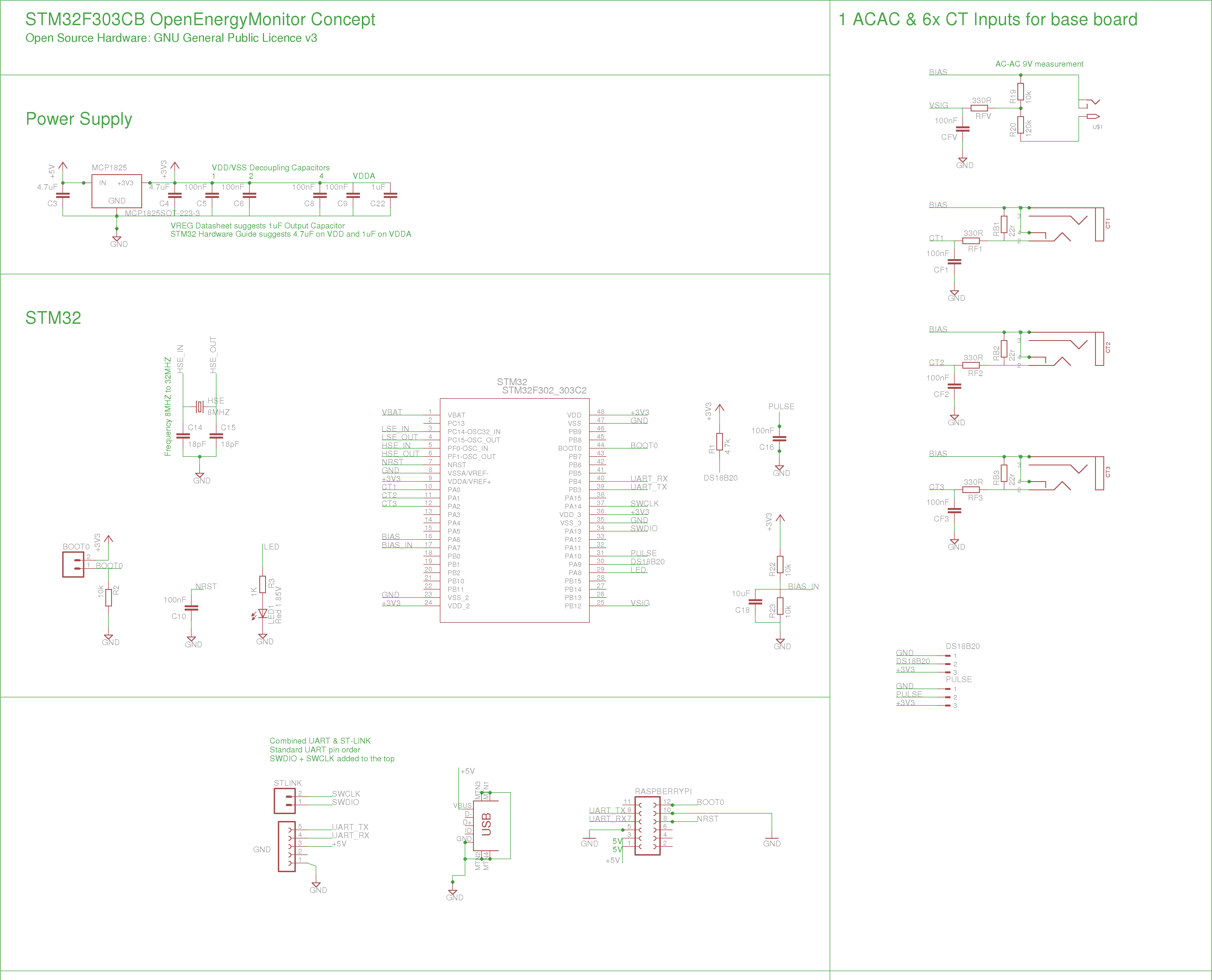
“Work through STM32 power supply, clock, programming sub circuits, check understanding, component sourcing. Put together base board design (equivalent of a STM blue pill, or Ken’s ARMIGO) potentially with a couple of CT and ACAC sensor inputs for initial testing.”
I’ve now put together this first design and will be sending it off to ragworm hopefully tomorrow. I’m fully expecting this prototype to have errors as it’s my first design with this chip. If anyone can spot any, please let me know
Bearing in mind that the intention of this design is just to test the basics and not to fulfil the longer term project goal of a more capable multi-CT unit, here is the spec:
This is one of those rushing out the door haven’t got time to think it through time comments, so take it with a grain of salt and if you’ve already considered it disregard.
I wonder if it’s worth building some sort of LPF into the op-amp mid-rail configuration to ensure it’s as clean as possible. Others here (@calypso_rae?) have a lot more experience building shared low-impedance mid-rails than I do, so you might want to compare your mid-rail design with theirs. I’m pretty sure stm run all the op-amp pins to the outside world, so you should be able to do anything that you could do with a discreet op-amp.
Thanks @dBC, at the moment I have a 10uF capacitor across the bias voltage divider on the input to the buffer. When I experimented here with the oscilloscope it didn’t make much difference. The bias did seem very stable, e.g no visible indication of interference from the ACAC Voltage adapter. Happy for input on how to improve and I will search for other’s work on this as you suggest.
Thanks for the quick comment.
Here’s the schematic for easier access to what’s in the design so far: